Publisher’s version / Version de l'éditeur:
Proceedings of the ASME 2015 34th International Conference on Ocean,
Offshore and Arctic Engineering, OMAE2015, May 31-June 5, 2015, St. John's,
Newfoundland, Canada, 2015-05-31
READ THESE TERMS AND CONDITIONS CAREFULLY BEFORE USING THIS WEBSITE. https://nrc-publications.canada.ca/eng/copyright
Vous avez des questions? Nous pouvons vous aider. Pour communiquer directement avec un auteur, consultez la première page de la revue dans laquelle son article a été publié afin de trouver ses coordonnées. Si vous n’arrivez pas à les repérer, communiquez avec nous à [email protected].
Questions? Contact the NRC Publications Archive team at
[email protected]. If you wish to email the authors directly, please see the first page of the publication for their contact information.
NRC Publications Archive
Archives des publications du CNRC
This publication could be one of several versions: author’s original, accepted manuscript or the publisher’s version. / La version de cette publication peut être l’une des suivantes : la version prépublication de l’auteur, la version acceptée du manuscrit ou la version de l’éditeur.
For the publisher’s version, please access the DOI link below./ Pour consulter la version de l’éditeur, utilisez le lien DOI ci-dessous.
https://doi.org/10.1115/OMAE2015-42079
Access and use of this website and the material on it are subject to the Terms and Conditions set forth at
Hydrodynamic study of submerged ice collisions
Chander, Subodh; Akinturk, Ayhan; Colbourne, Bruce
https://publications-cnrc.canada.ca/fra/droits
L’accès à ce site Web et l’utilisation de son contenu sont assujettis aux conditions présentées dans le site LISEZ CES CONDITIONS ATTENTIVEMENT AVANT D’UTILISER CE SITE WEB.
NRC Publications Record / Notice d'Archives des publications de CNRC:
https://nrc-publications.canada.ca/eng/view/object/?id=f632acc6-fcbc-4b50-b99d-7595a65e3071 https://publications-cnrc.canada.ca/fra/voir/objet/?id=f632acc6-fcbc-4b50-b99d-7595a65e3071
HYDRODYNAMIC STUDY OF SUBMERGED ICE COLLISIONS
Subodh Chander∗ Department of Ocean and Naval
Architectural Engineering Memorial University of Newfoundland
St.John’s, Canada NL A1B 3X5 Email: [email protected]
Ayhan Akinturk
Ocean, Coastal and River Engineering National Research Council Canada
St.John’s, Canada, NL A1B 3T5 Email: [email protected]
Bruce Colbourne
Department of Ocean and Naval Architectural Engineering Memorial University of Newfoundland
St.John’s, Canada, NL A1B 3X5 Email: [email protected]
ABSTRACT
Most of the research done on ice-structure interaction deals with the ice at the sea surface. Whereas majority of ice-strengthened regions of ships and offshore structures are well below the waterline. The aim of this research is to examine the mechanics of ice loads caused by submerged ice blocks colliding with the structure. The kinematics is an essential determinant of the energy that is available to drive the ice crushing process dur-ing the collision. The present research aims to develop a model to represent the mechanics of such collisions and set a direction for future work. This study includes experimental and numerical components. Various physical experiments have been conducted using a submerged ice model moving solely due to its buoyancy. Using high speed camera the experiments are recorded and anal-ysed to determine the kinematics of collision. These include lo-cation, velocity and acceleration of the model ice as a function of time. In parallel, numerical simulations have being conducted using FLOW 3DTM software. The results of the experiments are used to validate the numerical model of the underwater collision. The results shows that added mass plays an important role dur-ing the underwater impact collisions. The paper presents some preliminary results obtained during this research.
NOMENCLATURE
µ viscosity of the fluid. ρ density of the fluid.
∗Address all correspondence to this author.
R radius of the ice model. V Velocity of the ice model. a acceleration of the ice model. Re Reynolds number.
Ca added mass coefficient. Ac acceleration number.
INTRODUCTION
Apart from being a profitable shipping route Arctic hold a lot of untapped natural resources. Recent years we have seen lot of offshore activities in this region. This has brought along a lot of research on ice strengthening of ship and offshore structures. Although most of the research is focused on ice at sea surface not much work has been done on ice loads caused by submerged ice blocks. Even the available data on damages to ship due to ice collisions is limited as far as this issue is concerned. This research intends to throw some light on the issue of collisions with submerged ice pieces. The main focus of this study is to determine the mechanics of ice loads caused by submerged ice collision, which can further be used to determine the structural behaviour during the collision. The major part of this work is dedicated to study the kinematics of submerged ice during the collision.
The hydrodynamic forces acting on the model can be clas-sified as drag, buoyancy and added mass forces. An important parameter in collision with submerged ice pieces is the added mass of the ice.Added mass plays an important role in
acceler-Proceedings of the ASME 2015 34th International Conference on Ocean, Offshore and Arctic Engineering OMAE2015 May 31-June 5, 2015, St. John's, Newfoundland, Canada
ating, non-uniform motion resulting in fluid acceleration around the body. Although the term added mass maybe misleading, as there is no actual addition or subtraction of mass to the moving body but changes in inertia or changes in kinetic energy of the control volume, due to the motion, which can either be negative or positive [1].
1851 Stokes investigated the simple harmonic motion of sphere oscillating in a fluid. He omitted the convective terms in Navier-Stokes equation and derived the force expression. Later Basset (1888), Boussinesq (1885) and Oseen (1927) studied the rectilinear motion of sphere released in water. Although they also omitted the Navier Stokes convective terms, but they introduced an integral term, proving that the instantaneous force not only de-pends on instantaneous acceleration and velocity but also on the effect of the history of acceleration. Further Odar and Hamilton extended BBO (Basset-Boussinesq-Oseen) equation to include convective terms. [3] F(t) = −6πRµV φ −1 2Ca( 4 3πR 3)ρdV dt + (mf− mp)g − FH (1) Where (HistoryForce)FH= +6R2(π µρ) 1 2 Z t 0 a(t′) (t − t′)12 dt′ (2) φ= (1 + 0.15Re0.6p ) + 1.75 ∗ 10−2∗ Re p 1+ 4.25 ∗ 104 ∗ (Rep)−1.16 ; (3) Rep< 3 ∗ 105; (4) Ca= 1.05 − 0.066 A2 c+ 0.12 (5) Ac= V 2 2R(dV /dt) (6) EXPERIMENTAL SETUP
Series of hydrodynamic tests were conducted at Memorial University’s Fluids Lab, to determine the ice loads due to sub-merged ice block collision. The tests were conducted in a clear
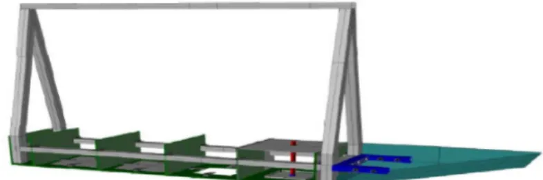
transparent tank in order to record the experiments using high speed camera. A Lexan ship model was fabricated with the sup-port of Tech Services at Memorial University. The model was fabricated around the aluminum frame as shown in fig(1) to pro-vide the structural rigidity. It was subdipro-vided into four compart-ments to restrict the flooding during the expericompart-ments. Each com-partment bottom was cut out to provide the opening for the load cell unit. The hatch arrangement was designed for easy access to the opening while conducting the tests. Water proof tape was used to further secure the leakage through the openings.
FIGURE 1. Model for hydrodynamic testing (side shells are not
shown in figure for inside view).
A waterproof load cell unit which consist of a dynamic load cell (DLC101) attached to the aluminum plate and connected to a rigid steel plate through a cylindrical steel shaft arrangement was lowered inside the compartment. The frequency of collision of ice loads was used as a limiting value for determining the fre-quency response and optimal dimensions of the aluminium plate. The size of load cell unit was just right to fit inside the bot-tom cut out of the model, without touching the edges in order to interact with the ice model without any losses during impact. The load cell unit was connected to the computer via amplifier to record the impact forces during the experiments.
A spherical ball 10cm in diameter made out of polypropy-lene material was used to model ice, since the density of polypropylene material is close to ice. This way we could avoid the unnecessary glitches occurring due to melting of ice at room temperature. The ice model was attached to a fishing line of 0.18mm diameter, which passed through L-shaped frame to the edge of tank so as to control the depth of ice model. The ice model was fully suspended in water and moved solely due to buoyancy and collided with the aluminum plate of load cell unit once the string was released. From the initial tests during the calibration it was found that for the depth of 5cm the collision happens in a short time interval of 800-500 microseconds. So to accurately record this data the dynamic load cell was config-ured to record at a frequency of 20 kHz. A high speed camera at 30,000 fps was used to record this event, to acquire the images
FIGURE 2. Model for hydrodynamic testing.
at the instant of collision. It was made sure that the camera is facing perpendicular to the plane of ice model. DC light sources were used to light the tank, in order to avoid the losses in frames due to the constant flickering of AC lights, since the frequency of recording was higher than that of AC lights.
The data acquired was used to determine the nature of veloc-ity and added mass during the collision. This was used to confirm the accuracy of numerical model.
EXPERIMENTAL PROCEDURE
At the start of experiment high speed camera was calibrated using the checkerboard to get the conversion from pixels to met-ric units. The board was placed parallel to the plane of ice model and the image was recorded. Knowing the actual dimensions of tank the pixels were converted into metric units.
High speed camera and load cell were connected together with a trigger. For each test load cell continuously records the data, the trigger was pushed at the moment ice model was re-leased, which sent a signal to the data acquisition system mark-ing the point of release of the ice model. Each test was repeated 5-6 times to get consistent data.
Load cell data was read through Labview. While a Matlab image analysis code was written to read the image files from high speed video and calculate the position of ice model at 30,000fps. Knowing the position at each time step, the data was used to interpolate the velocity and acceleration values during the colli-sion.
RESULTS AND DISCUSSION
FIGURE 3. Impact collision.
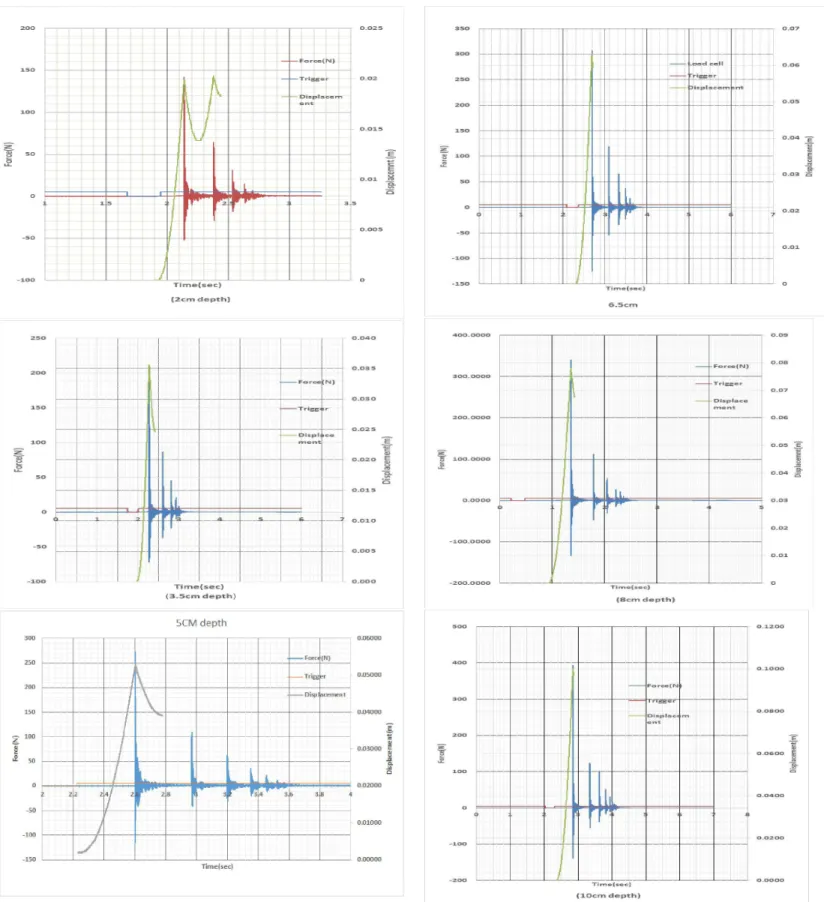
From the Matlab image analysis of the high speed video the position and velocity were determined. The load cell data were read through Labview. In order to remove noise and maintain the accuracy of data, moving average method was used. For the convenience data is plotted near the point of first impact. Fig.(4) and Fig(5) show the experimental data plots for displacement and impact forces. These data are used to analyse the collision me-chanics.
The numerical model using Flow3d was developed to com-pare the results. Using a FSI module in Flow3D ice structure interaction is simulated. Experimental data and Flow-3D results were compared to measure the accuracy of numerical model.
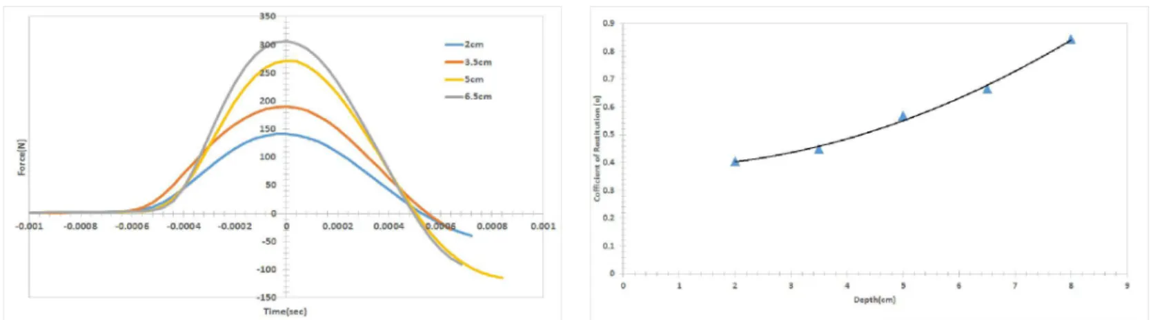
FIGURE 4. Displacement, Force plot for 2cm, 3.5cm and 5cm depths.
FIGURE 6. Impact Forces for 2cm, 3.5cm, 5cm, 6.5cm depths.
The impact force data of ice loads during collision shows that the contact occurs for a very short time interval of approxi-mately 0.0006 sec before the velocity drops to zero and changes its direction. During this time the kinetic energy of ice model is transferred to the plate. Although the material property of ice and structure determines the energy exchange the presence of fluid layer in between and around the contact region greatly in-fluences the impact forces.
As the ice model approaches the plate it starts to deform elastically due to the increasing hydrodynamic pressure. This results in transfer of part of the kinetic energy to elastic strain energy. This strain energy is released at the moment ice model velocity becomes zero resulting in a rebound.
Barnocky and Davis while studying the collision of sphere in fluids observed that even if the particle is completely rigid the in-crease of density of fluid during the compression could enhance the rebound of impacting particle from the surface. The increase of viscosity with pressure results in the fluid behaving like an elastic solid.
Velocity of ice model increases as it approaches the plate but just before the point of contact it starts decreasing as the gap reduces below one-diameter. This phenomenon does not occur in dry collisions where effect of surrounding fluids is negligible. From the velocity data effective coefficient of restitution is calculated. As shown in fig.(7) coefficient of restitution increases with the depth of release . The coefficient of restitution is calcu-lated as a ratio of rebound velocity to impact velocity. The coeffi-cient of restitution calculated in these experiments is an effective macroscopic value, since velocity is calculated from displace-ment recorded at 30,000fps which was filtered using moving av-erage method.
FIGURE 7. Effective Coefficient Of Restitution.
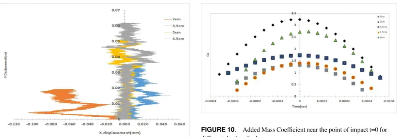
As the spherical ice model travels through the fluid it cre-ates a disturbance in its surrounding imparting a relative veloc-ity. The Reynolds number plot fig.(8) for different depths of re-lease indicates that a turbulent fluid region is created as the ice model travels toward the plate. This results in development of wake field around the spherical model as it exceeds the critical Reynolds number. The model initially travels in a straight line but gradually small lateral motions were noticed as it started ap-proaching the plate leading to a two dimensional path as captured by the image analysis. This is something different from what one can see in the case of free falling objects in fluids. Although the forces acting in both free falling and free rising objects in fluids are similar, but however they are different in direction.
FIGURE 8. Reynolds Number of ice model released at different
FIGURE 9. Motion of ice model in X-Y plane as released from dif-ferent depths .
Submerged ice collision is a case of free rising objects in fluids. One of the difference between free falling and free rising objects in fluids is density. Due to the higher density compared to the surrounding fluid, the nature of the flow developed around the object has practically no effect on its kinematics. Whereas a free rising object has a lower density compared to its surrounding fluid. Lower density means smaller mechanical inertia, which is unable to counter the effects of wake developed behind the moving object. Wake developed around the moving ice model forces it into small lateral motions as it moves vertically, leading to oscillatory motion around central axis. Due to the presence of a plate, the motion is also influenced by the fluid reflecting back from the boundary of aluminium plate. The deflection from central axis was the combined effect of wake and reflecting fluid. It was noticed that the experiments with lower release depths (near plate) resulted in larger deflections from the mean path compared to the larger depths, Fig(9). This can be explained due to the disturbance in surrounding fluid generated by the motion of the model, which is reflected from the aluminum plate and interferes early in the lower depths of release, while for higher depths it was predominately the wake effect which lead to the onset of oscillatory motion.
Added Mass Calculation
The values of added mass were calculated using equation(1) by substituting the experimental values of velocity and accelera-tion at each time step obtained from image analysis. The values of added mass coefficient were found close to 0.5 for the lower values of Reynolds number but a sudden increase occurs as the ice model gets close to the aluminium plate.
FIGURE 10. Added Mass Coefficient near the point of impact t=0 for different depths of release.
Introducing the impact force term in equation (1), which is the force measured by load cell during the collision,we can cal-culate the new added mass values, which will include the effects of collision. F(t)−FI(t) = −6πRµV φ − 1 2Ca( 4 3πR 3)ρdV dt +(mf−mp)g−FH (7) Also the collision occurs at a higher Reynolds number, which reduces the effect of history force present in the equation. Although it does have the effect on the bouncing motion of the particle after first impact.[12]
Added mass is the measure of kinetic energy of the object transferred to the control volume as the ice model travels through the fluid and collides with the wall. This transfer of kinetic en-ergy is affected by the wake and the disturbance in fluid in front of the moving object. This explains for the higher values of added mass coefficients for 2cm release depth added mass coef-ficients fig(10). In all cases added mass coefficient values reach maximum at the point of impact (t=0)
CFD MODEL
The unsteady numerical simulations were performed with the commercial software, FLOW3D, based on finite difference or finite Volume method. The software solves Reynolds averaged Navier-Stokes(RANS) equation using a turbulence model.
The computational mesh is subdivided into a grid of variable-sized hexahedral cells. For each cell, average values for flow parameters are calculated at discrete time using a staggered grid technique.
The mesh was defined to represent the fluid volume. Mesh planes were used near the ice model and at the interface to
ac-FIGURE 11. Flow3d mesh.
curately capture the collision. Different mesh sizes were stud-ied.After sensitivity analysis,it was decided to use 6.25 mm mesh along z-axis and 0.028mm mesh near the interface. For X and Y axes we used 5.5mm mesh near ice model mesh planes and 29mm outside. Flow3D uses a two-phase VOF (volume of fluid) and a fractional area volume representation (FAVOR) in combi-nation during the simulation. Due to the simple structured or-thogonal grid, it is very easy to interpolate the interface, com-pared to unstructured tetrahedral meshes. The boundary condi-tions were defined on the mesh planes itself. Stagnation pressure boundary condition was defined for the max plane, while Z-min (bottom plane) was defined as a wall. The X and Y planes were defined as symmetry boundary conditions.
(RNG) k-epsilon model was used as a turbulent model, since it accounts for the effects of smaller scales of motion. Also it has a good convergence rate and relatively low memory require-ments.
General Moving Objects(GMO) model was used to simulate moving ice in water. The motion was dynamically coupled with 6 degrees of freedom (DOF) to fluid. At each time step, area and volume fractions are calculated to describe the object location and motion. GMO removes the need to design a moving mesh around the ice model.The underwater ice collision is a case of coupled motion of light moving object, in order to improve the stability implicit GMO model was used.
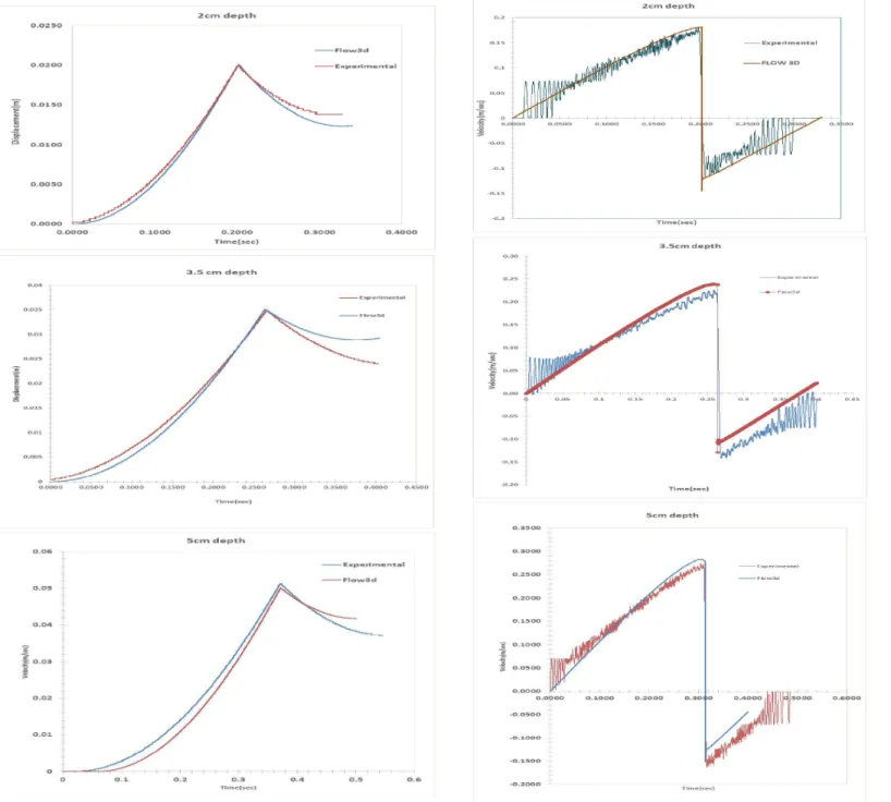
FIGURE 13. Flow3d and Experimental displacement plots for 2cm,3.5cm and 5cm depths.
FIGURE 14. Flow3d and Experimental Velocity plots for 2cm,3.5cm and 5cm depths.
Comparing the displacement and velocity of FLOW-3D with experimental data, Fig.(13) and Fig.(14) shows a close resem-blance in kinematics of submerged ice collision.
CONCLUSION
In this research, we conducted experimental and numerical study at high Reynolds number. Both the results seems to agree well. It was seen that the nature of flow around the model effects how it interacts with the structure. The CFD model employed was an extremely useful tool in analyzing kinematics of colli-sion. The study focused on different hydrodynamic forces act-ing duract-ing the collision. The results show that added mass plays an important role during the underwater collision. These tests were done for a stationary plate. Further tests will be conducted for moving plates to determine the effects of velocity on impact forces. This research intends to set a direction in this regard for future work.
ACKNOWLEDGMENT
This research has been done under STePS2 project, under the leadership of Dr. Bruce Colbourne and Dr.Ayhan Akin-turk, and was supported by: ABS, Atlantic Canada Opportu-nities Agency, BMT Fleet Technology, Husky Oil Operations Ltd, Research and Development Council Of Newfoundland and Labrador, Samsung Heavy Industries and National Research Council of Canada.
REFERENCES
[1] Turgut”Sarp”Sarpkaya, Wave forces on offshore structures Cambridge university press,New York, NY,2010
[2] L. Millne-Thomson, MacMillan Education, London ,1968 J. Fluid Mech.,Vol. 18, PP. 302-314 ,1964,.
[3] F. Odar and W. S. Hamilton,, Forces on a sphere accelerat-ing in a viscous fluid.J. Fluid Mech.,Vol. 18, PP. 302-314 ,1964,.
[4] R. Clift, J. R. Grace and M. E. Weber, Bubbles, Drops, and Particles.Academic Press, New York, NY ,1978.
[5] M.Rostami,A.Ardeshit,G.Ahmadi,P.J.Thomas. On the mo-tion of high reynolds particles in a quiescent fluid. Amirk-abir Journal of Science and Technology/Vol.17/No.64-B [6] C.E.Brennen. 1982, A review on added mass and fluid
iner-tial forces.Naval civil engineering lab, California.
[7] C. Crowe, M. Sommerfeld and Y. Tsuji, Multiphase Flows with Droplets and Particles.CRC Press, Boca Raton ,1998. [8] K.Masmoudi,N.Lecoq,R.Anthore,F.Bostel,F.Feuillebois,
Accurate measurement of hydrodynamic interactions between a particle and walls. Experiments in Fluids 32, Springer-Verlag ,2002.
[9] Alexandr I.Korotkin Added masses of ship structures Springer Science,2009.
[10] M. Abbad, O. Caballina and M. Souhar Experimental in-vestigation on the history force acting on oscillating fluid spheres at low Reynolds numberPHYSICS OF FLUIDS, Vol. 16, PP. 3808-3817 ,2004
[11] P. Alexander, High order computation of the history term in the equation of motion for a spherical particle in a fluidJ. Sci. Comput. 21 (2004) 129134.
[12] Mohammad Rostami,Abdullah Ardeshir ,Goodarz Ah-madi,Peter Joerg Thomas Can the history force be ne-glected for the motion of particles at high subcritical reynolds numbers range? International Journal of Engi-neering (IJE) Vol. 19, No. 1, December 2006 - 23 . [13] Patricia Ern, Frederic Risso, David Fabre, and Jacques
Magnaudet, Wake-Induced Oscillatory Paths of Bodies Freely Rising or Falling in FluidsAnnu. Rev. Fluid Mech. 2012. 44:97 - 121.
[14] McLaughlin,M. An experimental study of particle-wall col-lisions relating to flow solid particles in a fluidPh.D. The-sis, California Institute of Technology (1968).
[15] Kharaz, A., Gorham, A study of the restitution coeffi-cient in elastic-plastic impact.Philosophical Magazine Let-ters,2000, Vol.80,No.8,549-559.