Publisher’s version / Version de l'éditeur:
Vous avez des questions? Nous pouvons vous aider. Pour communiquer directement avec un auteur, consultez la première page de la revue dans laquelle son article a été publié afin de trouver ses coordonnées. Si vous n’arrivez pas à les repérer, communiquez avec nous à [email protected].
Questions? Contact the NRC Publications Archive team at
[email protected]. If you wish to email the authors directly, please see the first page of the publication for their contact information.
https://publications-cnrc.canada.ca/fra/droits
L’accès à ce site Web et l’utilisation de son contenu sont assujettis aux conditions présentées dans le site LISEZ CES CONDITIONS ATTENTIVEMENT AVANT D’UTILISER CE SITE WEB.
8th Canadian Marine Hydromechanics and Structures Conference [Proceedings],
2007
READ THESE TERMS AND CONDITIONS CAREFULLY BEFORE USING THIS WEBSITE. https://nrc-publications.canada.ca/eng/copyright
NRC Publications Archive Record / Notice des Archives des publications du CNRC :
https://nrc-publications.canada.ca/eng/view/object/?id=d65fe116-07fb-4503-a673-7ef9ef17eb15
https://publications-cnrc.canada.ca/fra/voir/objet/?id=d65fe116-07fb-4503-a673-7ef9ef17eb15
Archives des publications du CNRC
This publication could be one of several versions: author’s original, accepted manuscript or the publisher’s version. / La version de cette publication peut être l’une des suivantes : la version prépublication de l’auteur, la version acceptée du manuscrit ou la version de l’éditeur.
Access and use of this website and the material on it are subject to the Terms and Conditions set forth at
Performance characteristics of a podded propulsor during dynamic
azimuthing
Performance Characteristics of a Podded Propulsor During
Dynamic Azimuthing
Islam M. F
1, Akinturk A
2, Liu P
2and Veitch B
11Institute for Ocean Technology, National Research Council Canada St. John’s, NL, A1B 3T5, Canada
2Faculty of Engineering and Applied Science, Memorial University of Newfoundland St. John’s, NL, A1B 3X5, Canada
Email: [email protected]
A
BSTRACTThis paper presents some of the results obtained during recent opens experiments performed with a podded propulsor model. The model propulsor is instrumented to measure thrust and torque of the propeller, three orthogonal forces and moments on the unit, rotational speed of the propeller, azimuthing angle and azimuthing rate. The model was first tested at various sets of static azimuthing angles with varying advance coefficients. These tests were followed by tests in which the azimuthing angle was varied dynamically. The results for propeller thrust (KT) and torque (KQ) as well as unit thrust (KFX) are given for the dynamic azimuthing cases. Comparisons of the same parameters between the tests with static and dynamic azimuthing angles are also presented.
1. I
NTRODUCTIONPodded propulsors have become a popular main propulsion system. It is accepted that a podded propulsor allows more flexibility in design of the internal arrangement of a ship, potentially reduced noise and vibration, and increased maneuverability, especially in confined space [1].
The complexity of flow interactions between the propeller and pod in straight course operations limits the complete understanding of its hydrodynamics. The complexity increases when the pod propulsors operate under different azimuthing conditions. In azimuthing conditions, the inflow to the propeller is transient. In this operating condition, the propulsor produces forces and moments, which vary in a nonlinear manner with azimuthing angle and rate, propeller rotational speed and advance velocity. The
major source of failure of podded propulsors is the bearing failure (excessive bearing force) and this failure is primarily attributed to the incorrect prediction of bearing forces on the propulsors under different operating conditions [2]. It is thus necessary that the forces and moments on the propulsors at different straight course and azimuthing conditions be studied for the proper understanding of the issues. This essentially will quantify the functional relationship between the azimuth angle and the bearing load imposed on the propulsor.
The complexity of the podded propulsion system limits the study primarily to experimentation. It is important to conduct tests at varying azimuthing angles to enhance the understanding of the hydrodynamics. However, reported research associated with hydrodynamic behavior of podded propulsors subjected to azimuthing conditions is sparse [3]. Experimental investigations into pod propulsors’ behavior at different static and dynamic azimuthing angles will provide valuable information on hydrodynamic performance in the azimuthing conditions and on complex flow behavior around the systems.
Szantyr [4, 5] published one of the first sets of systematic experimental data on podded propulsors as the main propulsion unit with static azimuth angles. The tests measured the axial and transverse loads and used traditional non-dimensional coefficients to analyze the data. The study was limited to ±15° azimuth angles. In the work, the effect of an azimuth angle on propeller torque was not studied. Grygorowicz and Szantyr [6] presented open-water measurements of podded propulsors both in puller and pusher configurations in a circulating water channel. Heinke [7] reported systematic model
2 test results with a 4- and 5-bladed propeller fitted to a generic pod housing in pull- and push-mode. In the report, the author presents systematic data for forces and moments on the propeller and pod body at different static azimuthing angles. The study also included the effect of cavitation at conditions for a blocked propeller (no propeller rotation), low number of revolutions (simulating crash stop) and at the design speed and revolutions with a dynamically turning pod. Both push and pull modes of the propulsors were tested. The forces and moments of the propeller and podded drive show a strong dependency on the propeller loading and azimuthing angle. The results show that the open water characteristics are mostly irregular for the astern thrust conditions in the azimuthing angle range 90° to 270° due to flow separation at the propeller blades and pod housing. It has also been claimed that forces and moments observed in the dynamic azimuthing conditions were slightly higher than those obtained in tests at fixed azimuthing angles. The increase of the azimuthing rate leads to a small increase in the maximum forces and moments. Nevertheless, the obtained results demonstrate that the pseudo-steady approach is quite acceptable for predicting forces and moments on propellers and podded drive systems. Clearly, the tests were a significant step in understanding the hydrodynamics of podded propulsors and further study will enhance the knowledge.
Stettler et al. [8] investigated the dynamics of azimuthing podded propulsor forces with emphasis on the application of nonlinear vehicle maneuvering dynamics. In spite of the fact that the facility was able to measure both pseudo-steady (constant propeller advance coefficients and azimuth angle) and dynamic forces on the unit, the report offered only pseudo-steady results for a broad range of azimuthing angles and advance coefficients. Those results were a set of pseudo-steady functions for the thrust, the normal force, the torque and the steering moment where the nonlinear nature of vectored propulsion was evident. Unique PIV images of wake velocity fields and vorticity distributions behind the propeller in oblique flows under pseudo-steady and dynamic conditions were presented.
In a study of podded propulsor failures, bearing failure was identified as one of the most significant causes of mechanical failure of the propulsors [2]. Detailed study on the bearing forces and moments due to the rotation of the propeller and the azimuthing of the pod unit is required to provide sufficient information to the bearing designer to obtain optimum designed bearing. The present study on the azimuth conditions aims to improve the
understanding of the behavior of forces and moments that act on the pods.
Section 2 details the geometry of the propeller and pod-strut models used in this study, while section 3 presents a brief description of the apparatus and testing techniques used. Experimental results and discussions are provided in Section 3, followed by conclusions in Section 4.
2. E
XPERIMENTALS
ET-
UP2.1 Pod Model
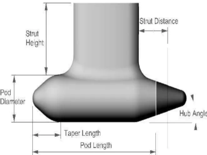
The experiments included tests on a model propeller with a pod unit comprising a combination of a pod shell and a strut. The propeller used in the experiments has a hub taper angle of -15° (Pull-15°, right handed propeller). It has four blades with a diameter, D of 0.20m, pitch-diameter ratio (P/D) of 1.0 and expanded area ratio (EAR) of 0.6. The geometric particulars of the propeller are given in [9]. The geometric particulars of the pod-strut model are defined using the parameters depicted in Figure 1. The values for the model propulsor were selected to provide an average representation of in-service, full-scale single screw podded propulsors. The particulars of the pod-strut body tested are shown in Table 1.
Figure 1. Geometric parameters used to define pod-strut geometry.
External Dimensions of the Model Pod: Pod 1
Propeller Diameter, D, mm 200 Pod Diameter, DPod, mm 102.9 Pod Length, LPod, mm 304 Strut Height, SHeight, mm 222 Strut Length at Pod, mm 232.0 Strut Length at Top, mm 132.9 Strut Distance, SDist, mm 74.1
Strut Width, mm 44
Fore Taper Length, mm 63
Fore Taper Angle 15°
Aft Taper Length, mm 81.5
Aft Taper Angle 25°
Table 1. Geometric particulars of the pod-strut model.
2.2 Experimental Apparatus and
Approach
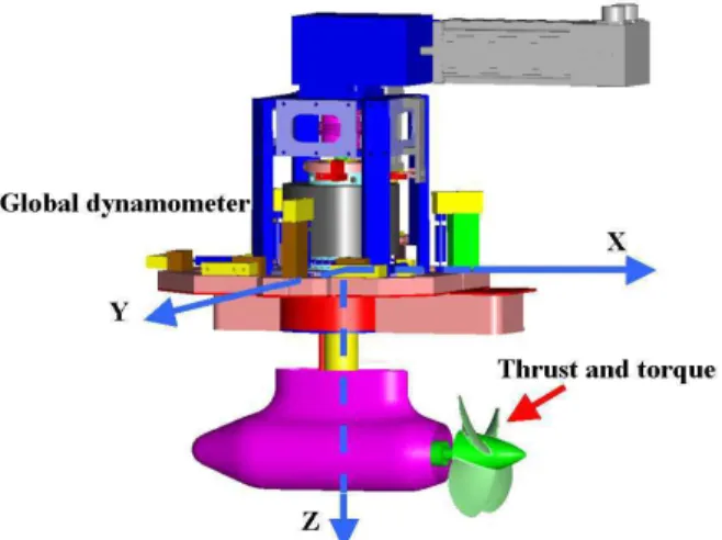
The open water tests of the pod in straight course and azimuth conditions were performed in accordance with the ITTC recommended procedure, Podded Propulsor Tests and Extrapolation, 7.5-02-03-01.3 [10], and the description provided by Mewis [11]. A custom-designed pod dynamometer system was used to measure propeller thrust, torque, and unit forces. The pod dynamometer measures the thrust and the torque of the propeller on the propeller shaft very close to the propeller hub. The global dynamometer, which consists of six in-line load cells, measures the unit forces in three coordinate directions. The moments on the pod unit are then derived. A motor mounted at the top of the global dynamometer drives the propeller shaft through an internal gear arrangement. Another motor arrangement mounted at the top of the seal plate turns the whole pod arrangement in a continuous motion about the vertical axis (thus providing dynamic azimuthing). The six-component global dynamometer has three load cells measuring forces in the Z (vertically downward) direction; one load cell measuring forces in the X direction (in the direction of propeller advance) and two load cells measuring forces in the Y direction (across the propeller advance direction), see Figure 2. Figure 3 shows the open boat that was used to test the pod model.
Figure 2. Pod and the global dynamometer system.
Figure 3. The open boat to test podded propulsors. XYZ reference frame is fixed to the opens boat (and
also the global dynamometer as shown in Figure 2) and the positive X axis coincides with the direction of
advance for the opens boat.
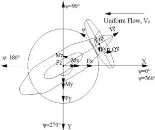
The global dynamometer was calibrated using the method described in [13] and [14]. The methods take into account cross-talk between the six load cells and produce an interaction matrix to convert the voltage output into the forces and moments in the three coordinate directions. The definition of the forces, moments and co-ordinates that were used to analyze the data and present the results is shown in Figure 4. The coordinate centre coincided with the intersection of the horizontal axis through the propeller shaft centre and the vertical axis through the strut shaft center.
4 Figure 4. Definitions of forces, moments, co-ordinates of a puller azimuthing podded propulsor. In dynamic azimuthing tests, the pod unit with the propeller is rotated about the vertical axis, Z, (azimuthing) in a continuous motion while the whole test unit is moved forward at a specific advance velocity and propeller rotational speed. Measurements are taken of the forces and moments acting on the propeller and the whole pod unit at different advance coefficients, and at different dynamic azimuthing rates. Typically, a full scale podded propulsor azimuths at a rate of 2.5°/s at the vessel’s service speed (requirement from the SOLAS, [14]). During maneuvering at slow speeds where less torque is required than the full speed mode, the azimuthing rate is approximately 5°/s. Depending on the ratio of the maximum vessel speed to the maximum steering torque at the lower speeds, a maneuvering at 12°/s azimuthing rate can be considered as a special case [14]. For the present dynamic azimuthing study, the tests were conducted at the model scale rates of 2°, 5°, 10°, 20° and 30°/s with various sweep angles between 0° and 360°. Measurements were made at different advance coefficients ranging from J=0.0 to J=1.20 and at two different propeller rotational speeds. Some tests were performed at high advance coefficients with low propeller rps because of the expected very large forces and moments during a crash stop maneuver [15].
Detailed results and discussion of the tests done with static azimuth angles are presented in [16]. The following section presents only the comparisons between the static azimuth angle case and the dynamic azimuthing for selected parameters.
3. R
ESULTS ANDD
ISCUSSIONSTwo types of tests were carried out: tests with static azimuthing angles and tests with the pod dynamically azimuthing. In both cases, the pod operated in pull mode. The static azimuthing angles were varied from 0° to 360° at approximately 30° intervals. During the tests the following parameters were recorded: propeller thrust (T), propeller torque (Q), unit axial/longitudinal force (FX), unit side/transverse force (FY), unit vertical force (FZ), propeller rotational speed (n), propeller advance velocity (VA), azimuthing angle and rate, and water temperature. The moments (MX), (MY), and (MZ) were then derived from the components of the global dynamometer. The results are presented in the form of traditional non-dimensional coefficients as defined in Table 2.
Performance Characteristics Data Reduction
Equation J – propeller advance coefficient VA/nD KT – propeller thrust coefficient T/ρn2D4 10KQ – propeller torque coefficient 5 2 / 10Q ρn D
KFX – unit thrust coefficient, or Longitudinal force coefficient,
4 2
/
n
D
F
Xρ
KFY – transverse force coefficient
F
Y/
ρ
n
2D
4 KFZ– vertical force coefficientF
/
n
2D
4Z
ρ
KMX– moment coefficient aroundx axis
5 2
/ n D MX ρ KMY– moment coefficient around
y axis
5 2
/ n D MY ρ KMZ– moment coefficient around
z axis (steering moment)
5 2 / n D MZ ρ ρ – water density
VA - propeller advance speed, in the direction of carriage motion D – propeller
diameter n – propeller rotational speed T - propeller
thrust
F X, Y, Z - components of the hydrodynamic force on the pod Q - propeller
torque
M X, Y, Z - components of the hydrodynamic moment on the pod It should be noted that, propeller advance coefficient, J is defined using the propeller advance speed, VA in the direction of carriage motion (in the direction of X in the inertia frame), not in the direction of propeller axis. The propeller thrust, T is defined as the force in the direction of propeller axis, not the projected force on X-axis on the inertial frame.
Table 2. List of performance coefficients for the podded propulsor unit.
3.1 Data Reduction
Test with static azimuthing angles:
Figure 5 shows a sample time series data stream taken from one of the tests with static azimuthing angle. The first step in the reduction is to select segments corresponding to steady VA and n – shaded areas in the figure. Then the segment means are computed and used in the figures given for performance parameters, e.g. the curve marked with * in Figure 7.
Figure 5. Sample time series data from one of the tests with static azimuth angle
Tests with dynamic azimuthing:
Figure 6 shows a sample time series taken from one of the tests with dynamic azimuthing. Since the sweep angle for dynamic azimuthing cannot be covered within a test run in the towing tank in some cases, the sweep range was divided into sections with overlaps and completed over a number of test runs. In the figures given for performance parameters, the merged raw data for the dynamic azimuthing are used unlike the static case in which the segment means are shown.
Figure 6. Sample time series data from one of the tests with dynamic azimuthing.
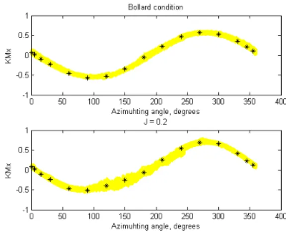
The figures in the following sub sections compare KT, 10KQ, KFX, KFY, KFZ, KMX, KMY and KMZ for two conditions: bollard pull (VA=0 m/s) and J = 0.2. For both cases, the pod was in pull mode and the propeller rotational speed was the same. The dynamic azimuthing rate was set to 10°/s.
3-1.1. Influence of Dynamic Azimuthing on Propeller Forces
Figure 7 compares the propeller thrust coefficient between the static and dynamic azimuthing. The top figure is for bollard condition while the bottom one is given for J = 0.2. As noted above, the values for static case are the segment means, while the raw time series are used for the dynamic azimuthing. It is clear
from the figure that the mean values of the static case coincide well with those of the dynamic azimuthing for both bollard and J=0.2 cases for 0° to 360°.
Figure 7. Propeller thrust coefficient both in static and dynamic azimuthing conditions for bollard pull
and at J = 0.2. ( * static; --- dynamic)
Figure 8 shows the same comparison for propeller torque coefficient, 10KQ. Similar to the above, the static means seem to correspond well with the means of the dynamic case for both bollard and J=0.2 cases and over the full circle, from 0° to 360°.
Figure 8. Propeller torque coefficient both in static and dynamic azimuthing conditions for bollard pull
and at J = 0.2. ( * static; --- dynamic) 3-1.2. Influence of Dynamic Azimuthing on Unit performance
From Figure 9. to Figure 14., comparisons are given for KFX, KFY, KFZ, KMX, KMY and KMZ. The * indicates the mean values of the case with static azimuth angle and the line represents the raw data of the case with dynamic azimuthing. In all cases, comparisons show a good agreement between the means of the static and dynamic azimuthing.
6 Figure 9. Longitudinal force (unit thrust) coefficient
of the pod model both in static and dynamic azimuthing conditions for bollard pull and at J = 0.2.
( * static; --- dynamic)
Figure 10. Transverse (side) force coefficient of the pod model both in static and dynamic azimuthing
conditions for bollard pull and at J = 0.2. ( * static; --- dynamic)
Figure 11. Vertical force coefficient of the pod model both in static and dynamic azimuthing conditions for
bollard pull and at J = 0.2. ( * static; --- dynamic)
Figure 12. Coefficient of MX (moment about the longitudinal axis) for the pod model both in static and dynamic azimuthing conditions for bollard pull and at
J = 0.2. ( * static; --- dynamic)
Figure 13. Coefficient of MY (moment about the transverse axis) for the pod model both in static and dynamic azimuthing conditions for bollard pull and at
J = 0.2. ( * static; --- dynamic)
Figure 14. Coefficient of MZ (moment about the vertical axis) for the pod model both in static and dynamic azimuthing conditions for bollard pull and at
4. C
ONCLUDINGR
EMARKSThe present set of experiments investigated the effects of static and dynamic azimuthing conditions on the propulsive performance of podded propulsors in puller configuration. A model pod fitted with a propeller was tested using the pod testing system at the Institute for Ocean Technology at the National Research Council Canada.
Comparisons for selected performance parameters are presented between the static and dynamic azimuthing cases. Based on the results presented in this paper, it is evident that the mean values coincide well for both cases as also suggested by Heinke [7]. As a logical extension to this study, further investigation is planned to quantify the influence of azimuthing rate on these parameters.
A
CKNOWLEDGEMENTSThis study on podded propellers is a Joint project between the National Research Council of Canada, Transport Canada and Memorial University. The authors thank Mr. Victor Santos-Pedro, Director, Design, Equipment and Boating Safety, Marine Safety, Transport Canada for continued support of in this research. Special thanks are extended to the members of Design and Fabrication and Experimental Facilities at the National Research Council of Canada’s Institute for Ocean Technology. Thanks are also extended to the technical service staff of Memorial University.
R
EFERENCES[1] Pakaste, R., Laukia, K., Wilhelmson, M., “Experience with Azipod Propulsion Systems on Board Marine Vessels", ABB Review, Issue 2, 12p., 1999.
[2] Carlton, J. S., “Podded Propulsors: some design and service experience”, The Motor Ship Marine Propulsion Conference, Copenhagen, Denmark, April 9-10, 7p., 2002.
[3] Atlar, M., Liu, P., Allema, Ir. J. H., Ishikawa, S., Kim, S., Poustoshniy, A. V., Sanchez-Caja, A., Sasaki, N., Traverso, A., “The Specialist Committee on Azimuthing Podded Propulsion: Final Report and Recommendations to the 24th ITTC”, Proceedings of the 24th ITTC - Volume II, pp.543-587., 2005
[4] Szantyr, J.A., “Hydrodynamic Model Experiments with Pod Propulsor”, International Symposium of Ship Propulsion (Lavrentiev
Lectures), State Marine Technical University, St. Petersburg, Russia, pp. 95-104., 2001a.
[5] Szantyr, J.A., “Hydrodynamic Model Experiments with Pod Propulsor”, Oceanic Engineering International, Vol. 5, No.2, pp. 95-103., 2001b.
[6] Grygorowicz, M. and Szantyr, J.A., (2004), “Open Water Experiments with Two Pods Propulsor Models”, In Proc. of the 1st International Conference on Technological Advances in Podded Propulsion, Newcastle University, UK, April, pp. 357-370.
[7] Heinke, H.J., “Investigation About The Forces And Moments At Podded Drives”, In Proc. of the 1st International Conference on Technological Advances in Podded Propulsion, Newcastle University, UK, April, pp. 305-320., 2004.
[8] Stettler, J.W. Hover, F.S. and Triantafyllou, M.S., “Preliminary Results of Testing on the Dynamics of an Azimuth Podded Propulsor Relating to Vehicle Manoeuvring”, In Proc. of the 1st International Conference on Technological Advances in Podded Propulsion, University of Newcastle, UK, pp. 321-338., 2004.
[9] Liu, P., “The Design of a Podded Propeller Base Model Geometry and Prediction of its Hydrodynamics”, Technical Report no. TR-2006-16, Institute for Ocean Technology, National Research Council, Canada, 16p., 2006. [10] ITTC – Recommended Procedures, “Propulsion,
Performance - Podded Propeller Tests and Extrapolation”, 7.5-02-03-01.3, Revision 00., 2002
[11] Mewis, F., “The efficiency of pod propulsion”, HADMAR 2001, Bulgaria, October, 7p., 2001. [12] Hess, D.E., Nigon, R.T., Bedel, J.W.,
“Dynamometer Calibration and Usage”, Research and Development Report No. NSWCCD-50-TR-2000/040, Hydromechanics Directorate, Carderrock Division, Naval Surface Warfare Center, West Bethesda, Maryland, 31p., 2000.
[13] Galway, R. D., “A Comparison of Methods for Calibration and Use of Multi-Component Strain Gauge Wind Tunnel Balances”, Aeronautical Report LR-600, NRC No. 18227, National Aeronautical Establishment, National Research Council, Canada, 40p., 1980.
8 [14] Sorsimo, S., Personal communication, Manager,
Sales, ABB., 2006
[15] Bushkovsky, V.A, Pustoshny, A.V., Vasiliev, A. and Veikonheimo, T., A Crash-stop Study for An Azipod-propelled Vessel, FAST 2003, Naples, Italy, Vol. 2, p. 1-6., 2003
[16] Islam M. F, Veitch B, Akinturk A, Bose N and Liu P “Experiments with Podded Propulsors in Static Azimuthing Conditions”, CMHSC 2007, St. John’s, Canada, 11p., 2007.