Development and Characterization of a Loop Heat
Pipe With a Planar Evaporator and Condenser
The MIT Faculty has made this article openly available.
Please share
how this access benefits you. Your story matters.
Citation
Kariya, H. Arthur, et al. “Development and Characterization of
a Loop Heat Pipe With a Planar Evaporator and Condenser.”
Proceedings of the ASME 2011 International Mechanical
Engineering Congress & Exposition, 11-17 November, 2011, Denver,
Colorado, ASME, 2011, pp. 857–62. © 2011 by ASME
As Published
http://dx.doi.org/10.1115/IMECE2011-63898
Publisher
ASME International
Version
Final published version
Citable link
http://hdl.handle.net/1721.1/119002
Terms of Use
Article is made available in accordance with the publisher's
policy and may be subject to US copyright law. Please refer to the
publisher's site for terms of use.
Proceedings of the ASME 2011 International Mechanical Engineering Congress & Exposition IMECE2011 November 11-17, 2011, Denver, Colorado, USA
IMECE2011-63898
DEVELOPMENT AND CHARACTERIZATION OF A LOOP HEAT PIPE WITH A
PLANAR EVAPORATOR AND CONDENSER
H. Arthur Kariya, Daniel F. Hanks, Teresa B. Peters, John G. Brisson and Evelyn N. Wang Department of Mechanical Engineering
Massachusetts Institute of Technology Cambridge, MA, 02139, USA
ABSTRACT
We present the development and characterization of an air-cooled loop heat pipe with a planar evaporator and condenser. The condenser is mounted vertically above the evaporator, and impellers are integrated both sides of the condenser with tight clearance. The planar geometry allows for effective convective cooling by increasing the surface area and the convective heat transfer coefficient. To ensure condensation across the area of the condenser, a wicking structure is integrated in the condenser. The evaporator incorporates a multi-layer wicking structure to maintain a thermal gradient between the vapor and liquid regions, which is used to sustain the vapor and liquid pressures necessary for operation. The loop heat pipe was demonstrated to remove 140 W of heat at a temperature difference between the evaporator base and inlet air of 50 °C. This work is the first step towards the development of an air-cooled, multiple-condenser loop heat pipe.
INTRODUCTION
Loop heat pipes (LHPs) are passive two-phase devices that utilize the latent heat of vaporization to transfer heat. Vaporization and condensation occur in the evaporator and condenser, respectively, and vapor and liquid lines connect the two components in a closed loop. Due to the use of phase change, LHPs have a high effective thermal conductivity between the evaporator and condenser, and are therefore promising solutions to thermal management of electronics [1, 2]. Compared to liquid-cooled LHPs, air-cooled LHPs offer significant advantages through the ease of installation due to the absence of a liquid circulation system. However, the design of an air-cooled LHP must consider the convective heat transfer resistance and the required fan power. The present study is a part of the development of a heat exchanger that incorporates the advantages of the high effective thermal conductivity of the heat pipe while minimizing convective thermal resistance to increase the overall coefficient of performance (COP).
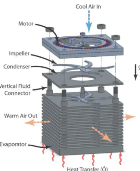
Figure 1. Schematic of air-cooled heat exchanger design. The layered structure constitutes the LHP. The thick bottom plate is the evaporator, and the multiple thin plates stacked above are the condensers. A low-profile motor is mounted on top of the structure, driving a shaft that spins the impeller blades that rotate between the condensers.
The heat exchanger being developed is a multi-layered structure, shown in Figure 1. The device utilizes a water-based LHP as the layered finning structure. Multiple planar condensers are stacked vertically above the evaporator, connected by vertical pipes that serve as vapor and liquid transport lines. The thin, planar condensers provide near-isothermal surfaces while increasing the available surface area for convection. Fan impellers are interdigitated between the condensers at tight clearance for forced convective cooling with minimal thermal boundary layer thickness. Air is drawn from the top of the device, through the central core of the stack, and exhausted radially from between the condensers. A low-profile, permanent-magnet synchronous motor is mounted at the top of
the stack to drive the impeller array. The target design consists of fifteen condensers to remove 1000 W with a 50 °C temperature difference between the evaporator base and the inlet air while keeping the electrical fan power to 33 W. Through the use of the LHP for near-isothermal finning and a narrow-clearance impeller array, a COP of 30 is expected [3].
This paper reports the development of the evaporator and condenser and the testing of a single-condenser version of the proposed design.
DESIGN AND MANUFACTURING OF THE PLANAR CONDENSER AND EVAPORATOR
Condenser
A planar, low profile geometry was adopted for the condenser (10 cm x 10 cm x 2.5 mm), with two vapor inlets and two liquid exits symmetrically located at the corners (Figure 2). To ensure condensation along the planar surface, a high-permeability (6.3*10-12 m2) wicking structure lines the inner surface of the condenser [4]. By forming a meniscus at the wick surface, the vapor and liquid phases are separated, and the location of condensation is fixed along the wick surface. This vapor/condensation space constitutes the majority of the condenser volume. By setting the liquid pressure below that of the vapor, a receding meniscus is formed at the interface of condensation. This receding meniscus guarantees stable operation of the condenser [5]. After condensation, the liquid is directed radially outwards through the wick before leaving the condenser (Figure 2b). Continued cooling during this radial flow results in subcooled liquid exiting the condenser. Sufficient subcooling is critical to prevent vapor flashing as the liquid exits the wick. “Subcooling” will quantitatively refer to the temperature difference between the vapor entering and liquid exiting the condenser, as these temperatures can be experimentally measured.
Figure 2. Schematic of condenser geometry. A) Separation of liquid and vapor regions by the spacer plate. B) Flow pattern schematic in the condenser. The condensed liquid travels a prescribed distance in the wick (subcooler) before exiting the wick.
The condenser was modeled using COMSOL Multiphysics (COMSOL, Burlington, MA) to achieve a subcooling of 8 °C (Figure 3). The condenser was modeled with an area of 10 cm x 10 cm, an outer shell thickness of 0.51 mm, a wick lining thickness of 0.5 mm and a subcooler length of 1 cm. The effective airflow convective heat transfer coefficient used for the analysis was 136.5 W/m2K, which was determined from a separate study [6]. To simulate the target operating conditions, condensation was modeled to occur at a vapor temperature 50 °C higher than that of the inlet cooling air. Additionally, condensation was modeled to occur uniformly across the entire wick-lined condensation surface.
Figure 3. Predicted temperature profile in the condenser for a temperature difference between the vapor and ambient of 50 °C and wick thermal conductivity of 25 W/m-K. The effect of the subcooling section is evident from the radial temperature gradient.
Figure 4. Fabrication procedure of the condenser. Sintering is performed in a tube furnace (Lindberg-Blue/Thermo Fisher Scientific, Waltham, MA, HTF55667C) under 5% hydrogen / 95% nitrogen atmosphere.
The modeled design is constructed by brazing together four (two pairs of) Monel 400 plates, chemically etched for the desired features. The pair consists of the outer shell and the
~2.5 cm
A
inner spacer plate (thicknesses of 0.51 mm and 0.94 mm, respectively) and forms half of the condenser. The spacer plate consists of two L-shaped subcooler section and partitions that seal and provide mechanical support for the finished condenser assembly. The fabrication assembly procedure for the condenser is outlined in Figure 4.
Evaporator
The evaporator was developed considering the temperatures of three key locations, shown in Figure 5: the heated base (bottom, TB), the vapor channel (TV), and the liquid
reservoir (top, TR). Liquid enters into the liquid reservoir at
the top, flows through the capillary wick, and evaporates near the heated base.
Design considerations for the evaporator include decreasing the temperature differential between the heated base (TB) and the vapor channel (TV) to minimize the effective
evaporator thermal resistance, and maintaining the pressure on the liquid side of the condenser below that of the vapor of the device. The mechanism adopted to control this pressure is to form a vapor bubble in the “liquid reservoir” of the evaporator. If the temperature of the liquid reservoir (TR) is maintained
below that of the vapor channels (TV), the (saturated) pressure
of the liquid reservoir will be maintained below the (saturated) pressure of the vapor channels.
To achieve this temperature difference, a multi-layer, monolithic wicking structure was developed. While a wick with high thermal conductivity is crucial near the vapor channels to minimize the evaporator thermal resistance, the wick must also possess insulating properties between the vapor channels and the liquid reservoir. To achieve both properties, a layered wick structure was developed (Figure 4 and 6), using sintered coarse (40-75 µm) and fine (10 µm) copper and Monel 400 powder (<44 µm). Vaporization occurs from the surface of the channels of a high thermal conductivity (90 W/m-K) copper wick fabricated from the fine powder. The fine powder size was chosen to maximize capillary pressure. This wick is separated from the liquid reservoir by a low thermal conductivity (2.3 W/m-K) wick fabricated from the Monel powder. In the liquid reservoir, a high permeability (1.6*10-12 m2) copper wick forms a bridge that enables heat transfer from the Monel wick to the top surface of the evaporator body, which is convectively cooled by airflow. [3]
Figure 5. Cross-sectional schematic of the multi-layer wicking structure. TB, TV and TR refer to the base, vapor channel (vapor) and
reservoir temperatures, respectively.
The geometry of the multi-layer wicking structure was designed using COMSOL Multiphysics, for a heat input of 1000 W, a convective boundary condition at the top surface (h=136.5 W/m2K), and a temperature difference between the base and ambient air of 50 °C. The Monel evaporator frame was modeled with a footprint of 10 cm x 10 cm and wall thicknesses of 2 mm and 1mm, for the sidewalls and top surface, respectively. The final design has wick thicknesses of 3.5 mm, 4 mm, and 4.5 mm for the liquid reservoir, Monel, and vapor channel wicks, respectively. The low thermal conductivity Monel wick layer is contoured to shield the liquid reservoir from excessive heat transfer through the evaporator frame as well as through the wick (Figure 5).
Figure 6 shows a temperature plot of the results of the COMSOL model. The hottest location of the reservoir is 3 °C below the vapor temperature, with a corresponding heat leak of 33 W. The resulting pressure difference between the vapor channels and liquid reservoir is 4.98 kPa. The expected temperature difference between the base and vapor is 2.75 °C for the 1000 W heat load, amounting to an effective evaporator thermal resistance of 0.003 °C /W.
Figure 6. Predicted temperature profile in the evaporator for a 1000 W heat load and ambient and base temperature of 30 °C and 80 °C, respectively. The contoured Monel layer is outlined in the cross sectional profile.
Fabrication of the multi-layered wicking structure is performed in a sequence of sintering steps as shown in Figure 7. The portions of the wick that form the liquid reservoir (coarse copper) and vapor channels (fine copper) are prefabricated in graphite molds. The prefabricated wick for the liquid reservoir is sintered onto the evaporator frame by using a thin layer of un-sintered powder (40-75 µm) as the bonding agent. Following this, Monel powder is poured and arranged over the attached liquid reservoir wick and sintered into place. The prefabricated vapor channel wick is then sintered to the Monel layer using a thin layer of copper powder (10 µm). To promote full contact between the copper base plate and the vapor channels, fine copper powder (10 µm) is used to sinter the plate to the wick. The copper base plate is then soldered (2%Ag-98%Sn) to the evaporator frame for a hermetic seal. Figure 8 shows a cross-sectional cut of a prototype evaporator with the different wick layers.
Figure 7. Fabrication procedure of the evaporator. Sintering is performed in a tube furnace under 5% hydrogen / 95% nitrogen atmosphere. The evaporator is oriented with the heat input side at top.
Figure 8. Cross-sectional image of prototype evaporator. The Monel wick layer is thicker (4 mm) for the final design.
CONSTRUCTION AND TESTING OF THE PLANAR LHP
The LHP was assembled by soldering (2%Ag-98%Sn) the vapor and liquid pipes to connect the condenser to the evaporator. The system was checked for leaks, and any leaks from the soldering process were mended with vacuum epoxy (Varian, Palo Alto, CA, Torr-seal). Afterwards, the LHP was evacuated and filled with degassed water. The degassing process consisted of four cycles of freezing the water, evacuating the non-condensable gases, and thawing. After filling, however, the pressure of the LHP was observed to rise above that of the vapor pressure of water. This was attributed to remnant non-condensable gases that were unable to be evacuated from the fine pore network in the wicking structure.
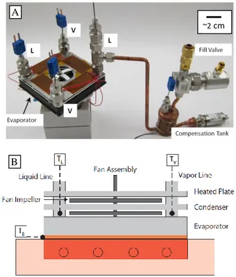
Figure 9. A) Image of assembled planar LHP with thermocouples. “V,” “L,” and “B” indicate vapor and liquid lines and the base, respectively. The compensation tank, which allows for operation as a capillary pumped loop, was not used for this study. The motor is not shown in this figure. B) Schematic of experimental setup, without the motor.
To closely simulate the condenser operation in the proposed air-cooled heat exchanger design, a heated aluminum plate with 4 kapton heaters (Omega Engineering, Stamford, CT, KHLV-102/5-P) was placed above the condenser to mimic a neighboring condenser. During testing, the plate was maintained at 50 ± 1 °C above the ambient air temperature. The input heat to the aluminum plate is not included in the calculation for the heat input to the LHP.
Each liquid and vapor line, as well as the evaporator base, was instrumented with type-T thermocouples (Omega Engineering, TMQSS-062G and 5TC-TT-T-40-36). A brushless DC motor was used to drive the impellers, which were 1.5 mm thick with an average clearance of 0.6 mm from the condenser and evaporator surfaces (Figure 9B). Testing was performed at a fan rotational speed of 5000 ± 50 RPM and an air inlet temperature 22–23.5 °C. A copper block with four cartridge heaters was used as the heat source.
The LHP temperatures were monitored while the heat input was varied between 80 and 200 W. The scaled heat input for a single condenser LHP was expected to be approximately 100 W, as the proposed heat exchanger utilizes 31 planar surfaces (15 condensers with 2 surfaces, as well as the top surface of evaporator) to remove 1000 W.
~2 cm
3 mm
A
RESULTS AND DISCUSSION
The planar LHP was characterized by observing the base temperature of the evaporator, the vapor temperature, and temperature of the liquid exiting the condenser. The key factors investigated were the level of condenser subcooling, evaporator thermal resistance, and the overall temperature response of planar LHP.
The temperature difference of the vapor entering and liquid exiting each of the condenser liquid ports (subcooling) is shown in Figure 10. Subcooling was observed to be higher than that predicted by the COMSOL model. Although the temperatures of the vapor entering the two lines of the condenser were equal, the temperatures of the cooled liquid leaving the two liquid ports were disparate. The disparity in the temperatures is attributed to a parasitic heat leak through a filling line that was attached to line L2. A peak exists on both temperature traces on Figure 10 at a heat input of approximately 110 W. The increase in subcooling below a heat load of 110 W is attributed to a higher overall temperature of the liquid entering the subcooling section of the condenser. This higher temperature increases the net heat transfer to the ambient air that results in a larger temperature change as the liquid transits the subcooler section. At higher heat input to the LHP, the air substantially warms as it flows radially outwards across the condensation area of the condenser. When the air reaches the subcooling section of the condenser, the higher air temperature reduces the heat transfer from the liquid in the subcooling section, and hence reduces the level of subcooling experienced by the liquid.
Figure 10. Temperature difference between the vapor entering and the liquid exiting the condenser as a function of the applied heat input to the LHP. L1 and L2 refer to the two liquid lines.
The temperature difference between the evaporator base and vapor was predicted by the model to be 2.75 °C for a heat load of 1000 W, hence the temperature difference for the range of heat inputs tested (80-200 W) is expected to be 0.2 to 0.6 °C. The experimentally observed temperature difference matched this range; however, since the precision of the thermocouples are of the same order as the temperature difference, the data can be interpreted only to be an indication that the thermal resistance is close to the expected value. Further testing at higher fluxes, which would require more condensers, would be
needed to experimentally confirm that the thermal resistance of the evaporator matches the prediction from the modeling.
Figure 11 shows the difference between the vapor temperature entering the condenser and the inlet air temperature, plotted against the heat input to the LHP. As the vapor temperature and evaporator base temperatures are nearly the same, the slope of the plotted points, 0.16 °C /W, represents the total thermal resistance of the LHP, from the base of the evaporator to the ambient air. With a temperature difference between the vapor and ambient air of 50 °C, 140 W is removed by the LHP. As a consequence, a 1000 W device would require approximately 11 condensers of this type to handle the heat load under similar conditions.
Figure 11. Temperature difference between the vapor temperature and inlet air temperature as a function of the applied heat input to the LHP.
CONCLUSION
As a part of the development of a multiple-condenser loop heat pipe (LHP) for an air-cooled heat exchanger, a LHP with a planar condenser and evaporator was designed, fabricated and tested. The condenser utilizes a novel design that incorporates a wicking structure to separate the liquid and vapor phases. A multi-layered, monolithic wicking structure was fabricated into the evaporator body to achieve low thermal resistance while maintaining a liquid reservoir at a reduced temperature. The two components were assembled into an air-cooled, planar LHP and experimentally characterized. The level of subcooling measured experimentally was noticeably higher than that predicted by computational modeling, and subcooling was found to peak at between 15 and 20 °C for a heat input of 110 W. The experimental results confirm that the condenser and evaporator can function together, allowing for a heat removal of 140 W with a temperature difference between the base of the device and inlet air of 50 °C.
ACKNOWLEDGMENTS
This work is supported by the Defense Advanced Research Projects Agency (DARPA) Microsystems Technology Office (MTO) Microtechnologies for Air-Cooled Exchangers (MACE) program, Grant Number W31P4Q-09-1-0007, with Dr. Tom Kenny and Dr. Avi Bar-Cohen as the program managers.
0 50 100 150 200 250 0 5 10 15 20 25 Heat Input(W) T V -T L ( C) L1 L2 0 50 100 150 200 250 0 10 20 30 40 50 60 70 Heat Input(W) T V -T A M B ( C)
REFERENCES
1. Maydanik Y.F., 2005. Review – Loop Heat Pipes, Applied
Thermal Engineering 25(5-6): 635-657.
2. Ku J., 1999. Operating Characteristics of Loop Heat Pipes, SAE 1999-01-2007.
3. McCarthy M., et al. 2010. Design and Analysis of High-Performance Air-Cooled Heat Exchanger with an Integrated Capillary-Pumped Loop Heat Pipe, 12th
Intersociety Conference on Thermal and Thermomechanical Phenomena in Electronic Systems.
4. Dominguez-Espinosa, F.A., 2011. Effect of Fabrication
Parameters on Thermophysical Properties of Sintered Wicks, Master’s Thesis, Massachusetts Institute of
Technology.
5. Hanks, D.F., et al. 2011. Characterization of a Condenser for a High Performance Multi-Condenser Loop Heat Pipe,
International Mechanical Engineering Congress & Exposition.
6. Peters, T.B., 2011. Personal Communication. .