HAL Id: cea-01760895
https://hal-cea.archives-ouvertes.fr/cea-01760895
Submitted on 9 Apr 2018
HAL is a multi-disciplinary open access
archive for the deposit and dissemination of
sci-entific research documents, whether they are
pub-lished or not. The documents may come from
teaching and research institutions in France or
abroad, or from public or private research centers.
L’archive ouverte pluridisciplinaire HAL, est
destinée au dépôt et à la diffusion de documents
scientifiques de niveau recherche, publiés ou non,
émanant des établissements d’enseignement et de
recherche français ou étrangers, des laboratoires
publics ou privés.
Effect of tube heat conduction on the pulsating heat
pipe start-up
Iaroslav Nekrashevych, Vadim Nikolayev
To cite this version:
Iaroslav Nekrashevych, Vadim Nikolayev.
Effect of tube heat conduction on the
pulsat-ing heat pipe start-up.
Applied Thermal Engineering, Elsevier, 2017, 117, pp.24 - 29.
Effect of tube heat conduction on the pulsating heat pipe start-up
Iaroslav Nekrashevych1, Vadim S. Nikolayev∗
Service de Physique de l’Etat Condens´e, CEA, CNRS, Universit´e Paris-Saclay, CEA Saclay, 91191 Gif-sur-Yvette Cedex, France
Abstract
In this work, we present our first simulation results on the start-up, functioning and stopping (dry-out) of the multi-branch pulsating heat pipe (PHP) accounting for the fluid-tube thermal interaction and bubble generation (boiling). A theoretical model that generalizes an earlier proposed approach is described. It is shown that the account of tube heat conduction changes substantially the simulated PHP behavior. In particular, in the presence of tube heat conduction, the simulated PHP cannot provide stable oscillations without bubble generation. While the bubble generation may not be directly involved in the development of first oscillations, its role is crucial in preventing the oscillations halt. The mechanism of the oscillation sustainment by bubble generation is discussed. The PHP simulation shows basic phenomena of bubble interaction and regimes observed experimentally in transparent PHPs. The PHP ceases functioning when the evaporator power is larger than a threshold. The liquid films are evaporated so the evaporator dries out completely and the oscillations stop; the evaporator temperature rises steeply.
Keywords: pulsating heat pipe, oscillation, liquid films, phase change, simulation
1. Introduction
Pulsating (or oscillating) heat pipe (PHP) is a simple capil-lary tube bent into branches meandering between hot and cold spots and partially filled with a two-phase, usually single com-ponent working fluid. During PHP functioning, a moving pat-tern of multiple vapor bubbles separated by liquid plugs forms spontaneously inside the tube. Because of their simplicity and high performance, PHP’s are often considered as highly promis-ing [1]. Their industrial application is however limited because the functioning of PHPs is not completely understood; the ab-sence of calculation tools that would allow their dimensioning is a substantial obstacle to their development.
During the last decade, researchers have extensively studied PHP [2, 3]. It has been observed by many researchers that the main flow pattern inside the PHP is the slug flow, i.e. the flow of the “Taylor bubbles” where the gas is surrounded by liquid films. A major part of mass exchange occurs on their interface with the vapor like in the conventional heat pipes. Since the mass exchange provides both a moving force for the oscillations and the heat exchange, the films are extremely important for the PHP functioning.
Because of complex bubble and plug interactions and non-stationary dynamics, correlation-based system level approaches fail to predict the heat transfer in multi branch PHP and its di-rect numerical simulation seems to be the only possibility. One dimensional (1D) simulation models is the best choice because they are the simplest and at the same time are capable to
de-∗Corresponding author: vadim.nikolayev@cea.fr, Ph.: +33169089488 1On leave from Heat Pipe Laboratory, Heat and Power Engineering Faculty,
National Technical University of Ukraine “Kyiv Polytechnic Institute”, Kyiv, 03056, Ukraine
scribe the relevant physical phenomena. The pioneering ap-proach [4] introduced basic principles for the 1D modeling. The PHP meander was represented by a straight tube with periodic boundary conditions; the evaporator, adiabatic and condenser sections followed each other sequentially. A coherent thermo-dynamic description of vapor has been introduced. The vapor was described as a compressible ideal gas which allowed its spring-like action. The heat conduction in the liquid plugs has been introduced. The imposed fixed temperatures Tc, Teat the
internal tube walls were assumed. Periodic oscillations were encountered. However, their amplitude was weak (smaller than the evaporator size), which contradicts the experimentally ob-served behavior.
One knows that the strongest heat and mass exchange oc-curs from thin liquid films. The films with uniform thickness δf, but varying length were introduced into the modeling [5]
of the simplest, single branch PHP so that a partial evaporator dry-out could be described. The introduction of the heat con-duction inside the tube walls [6] enabled the fluid-solid thermal interaction. The latter is quite important because it accounts for such effects as e.g. transfer of the heat from hot liquid plugs to the walls, heat accumulation in the solid and its later reinjec-tion into the fluid. Besides, much realistic imposed heat power thermal boundary conditions become possible to simulate. The approach [6] has been reused with some improvements by an-other group [7] without correcting the crucial default in the model [6]: unlike [4], the vapor heat exchange was described with an inconsistent equation (cf. [8]), without which it was ap-parently impossible to obtain large amplitude oscillations. The vapor phase modeling problem has been analyzed and a new, “film evaporation/condensation model” (FEC) has been devel-oped [9] for the single branch PHP. The FEC model is deprived
Nomenclature
c specific heat at constant pressure [J/(kg K)] D heat diffusivity [m2/s]
d tube inner diameter [m] hlv latent heat [J/kg]
L length [m]
M total number of bubbles or plugs m mass of vapor [kg]
N total number Nu Nusselt number P power [W]
p pressure; pi: in the bubble i [Pa]
q heat flux [W/m2] S cross-section area [m2] T temperature [Ti: of vapor] [K]
t time [s]
U heat transfer coefficient [W/(m2K)]
x, X abscissa measured along the PHP tube [m] Greek symbols
∆ difference δ thickness [m]
λ heat conductivity [W/(m K)] φ volume fraction of liquid in PHP ρ density [kg/m3 ] Superscripts l left r right Subscripts c condenser e evaporator f liquid film
f b feed back section (vertical in Fig. 1) i bubble or plug identifier
l liquid m meniscus next next bubble nucl nucleation p PHP spatial period sat at saturation t total thr threshold v vapor
w internal tube wall of the above mentioned shortcomings and truthfully reproduces
the experimental behavior both qualitatively and quantitatively, at least for the single branch PHP [9–11]. The FEC model has been generalized later to the multi-branch PHP [12] with the imposed temperatures Tc, Teof the internal tube walls. An
al-ternative film description where the film is divided by the equal length pieces of variable thickness has been introduced [13]. Within such an approach, it is also possible to describe the evap-orator dry-out [14]. The bubble generation has been introduced by the same group, which is an important step forward. Indeed, such an approach is much heavier computationally as one needs to in addition to liquid plugs, discretize the liquid films. Prob-ably for this reason, the wall temperature was assumed to be constant. The oscillation amplitude was small with respect to the evaporator size.
The main issue in the multi branch PHP is the oscillation start-up that one needs to master to develop reliable PHP for industrial needs. Because of multitude of parameters that may be relevant, it is a difficult task. For this reason, we began the start-up study with applying the FEC model to the simplest, sin-gle branch PHP [15, 16]. First, the start-up has been studied for the stepwise variation of the temperature Twof the internal tube
wall (simply “wall” in the following for brevity) from Tcto Te
[15]. It has been found that the dimensionless control param-eters for the start-up depended crucially on δf. The start-up in
the presence of the tube heat conduction and the fluid-wall heat exchange has been considered in the subsequent work [16]. A constant homogeneously distributed heat power Peapplied to
the evaporator has been simulated while the wall temperature Tcin the condenser was fixed. It has been found that the
non-zero tube conduction completely changes the start-up criteria. In particular, they become independent of the liquid film
pa-rameters. It has been shown that the tube thermal properties considerably influence the single branch PHP start-up.
The main problem of the published up to now PHP mod-eling results is that they fail to describe even qualitatively the usual bubble patterns observed experimentally. This paper pres-ents our first results of multibranch PHP simulation account-ing for the fluid-tube thermal interaction and bubble generation (boiling) with the same boundary conditions as in Ref. [16]: fixed Peand Tc. The in-house CASCO software (French
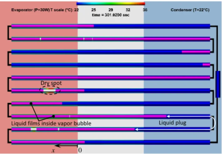
abbre-viation for Code Avanc´e de Simulation du Caloduc Oscillant: advanced PHP simulation code, cf. Fig. 1) has been used for simulations. The gravity is switched off; the discussed below simulations thus correspond to the horizontal PHP orientation. 2. FEC model with tube heat conduction
The simulation is based on the FEC model for the closed loop PHP described earlier [12]. The PHP meandering tube consisting of a sequence of different PHP sections is projected to a straight axis x. One PHP spatial unit of the length Lp =
2La+ Lc+ Leis assumed to contain the sections in the
follow-ing order: evaporator, adiabatic, condenser, and again adiabatic. The point x = 0 coincides with the beginning of evaporator (Fig. 1). Lt = NpLp+ Lf bis the total PHP length, where Lf b
represents the length of the feedback section (shown vertical in Fig. 1). The periodic boundary conditions are imposed in such a way that the local values for all the variables at the points x and x + Ltare the same for any x; the train of bubbles moves along
an infinite axis. Within such a description, the coordinate Xl iof
the left meniscus of the bubble i is always smaller than that of its right meniscus Xr
i; the bubble order does not change during
their motion. The total number M of bubble-plug couples may 2
0 x
Liquid films inside vapor bubble Dry spot
Liquid plug
Figure 1: The PHP geometry pictured by the PHP Viewer postprocessor of the CASCO software. Thin liquid films (in violet) cover the internal tube walls in-side of the vapor bubbles, except of the dry spot areas (white). The liquid plugs are shown in blue. The wall temperature is shown with the color varying from blue to red; its scale is indicated at the top. The round turns are not pictured for simplicity; black lines just connect equivalent points which correspond to the extreme points of each turn.
change in time because of bubble generation, coalescence and disappearance. The liquid plug which is the right neighbor to the bubble i is identified with the same index i. The left end of the plug is thus Xr
i and the right is X l i,next, where X l i,next = X l i+1 unless i = M, in which case Xl
i,next= X l
1+ Lt.
The following main assumptions are used:
1. Bubble and film (if any) occupy all the tube cross-section in the bubbles; liquid occupies all the tube within the liq-uid plugs (no dispersed flow).
2. The film is of the fixed thickness δf defined a posteriori
by the average plug velocity during the established os-cillations by using a formula conventional for the Taylor bubble film as described in [15].
3. The films are deposited by the receding meniscus and “eaten up” by the advancing meniscus.
4. Film evaporation leads to the reduction of the film area; the film condensation causes its increase unless it is im-possible (e.g. no dry area in the bubble; cf. assumption 2). In the latter case the condensed mass is equally dis-tributed between the neighboring liquid plugs to provide the fluid mass conservation.
5. The films may be partially or completely evaporated in the evaporator or adiabatic section. The film evaporation rate is proportional to the film area and to the local super-heating.
6. There is evaporation from each meniscus. Its rate is pro-portional to the local superheating at the meniscus posi-tion.
7. Vapor obeys the ideal gas equation of state and may be overheated [10], liquid is incompressible.
8. Bubbles and plugs disappear when their length becomes smaller than a small threshold, Lthr; a threshold mass mthr
is defined for a bubble.
9. Bubble of the length Lnuclis generated at any point x
in-side the plug i if the local superheating exceeds a nu-cleation barrier, Tw(x) − Tsat(pl) > ∆Tnucl, where pl =
pi+(pi,next−pi)(x − Xir)/(X l i,next−X
r
i) is the local
liq-uid pressure assumed to vary linearly along a plug. The nucleation barrier ∆Tnucldepends strongly on the surface
properties. It is assumed to be constant.
Note that unlike earlier bubble generation approaches, there are no preferential nucleation sites in the model.
The general algorithm and the structure of the CASCO code have been already discussed [12]. We describe here only the features that have to be changed in order to implement the fluid-wall heat exchange.
To simulate as precisely as possible the dry wall area under the conditions where Tw varies in space, a notion of the
effec-tive evaporator needs to be introduced. It is a part of the wall within the bubble i which is either dry (i.e. uncovered by the film) or along which Twexceeds Tsat(pi). In the latter case, the
film might be currently continuous but will rupture next time moment. There may be several effective evaporators per bub-ble and, accordingly, several film pairs formed by the right and left films. The number of effective evaporators is denoted Ne,i.
The left and right film edge positions (i.e. those of triple con-tact lines) are denoted with Xl,kf,i and Xr,kf,i for the kth effective evaporator, cf. Fig. 2. The following inequalities Xil ≤Xe,il,1 ≤ Xl,f,i1≤Xr,f,i1≤Xe,ir,1 ≤ · · · ≤Xl,Ne,i
e,i ≤X l,Ne,i f,i ≤X r,Ne,i f,i ≤X r,Ne,i e,i ≤X r i
are thus satisfied and should be enforced numerically to provide the correct film management. The film dynamics is described by the equations that interpret the assumptions 1-4,
x , , , e i l N f i X , , , e i r N f i X Xir ,1 , l f i X ,1 , r f i X l i X … vapor bubble i ,1 , r e i X , , , e i l N e i X , , , e i r N e i X ,1 , l e i X Effect. cond.1 Effect. evap. 1 Effect. evap. Ne,i Effect. cond. Ne,i Effect. cond. Ne,i+1
Figure 2: Geometry of the effective evaporators and condensers.
˙ Xl,kf,i= ˙ Xl i, if X l,k f,i≤X l iand ˙X l i ≥0 − ˙ mk f c,i 2ρπdδf
, if Xe,il,k≥Xl,kf,iand Xl,kf,i< Xr,kf,i
− ˙ ml,kf e,i ρπdδf , otherwise. (1) ˙ Xr,kf,i = ˙ Xir, if Xr,kf,i ≥Xirand ˙Xir≤0 ˙ mk+1 f c,i 2ρπdδf
, if Xe,ir,k≤Xr,kf,i and Xl,kf,i < Xr,kf,i ˙
mr,kf e,i ρπdδf
, otherwise.
(2)
where the dot means the time derivative. According to the as-sumption 5, the vapor mass change of the ith bubble caused by
the evaporation of right and left films of the kth effective evap-orator are defined by the expressions
˙ mr,kf e,i= Ufπd hlv Xe,ir,k Z Xr,k f ,i (Tw(x) − Tsat,i)dx, (3) ˙ ml,kf e,i= Ufπd hlv Xl,kf ,i Z Xl,k e,i (Tw(x) − Tsat,i)dx, (4)
where Tsat,i = Tsat(Pi) and Uf ∼ λl/δf within a coefficient of
the order unity [9]. The vapor mass change of the ith bubble caused by the condensation in the kth effective condenser is
˙ mkf c,i= Ufπd hlv Xe,il,k R Xl i (Tw(x) − Tsat,i)dx, k = 1 Xl,ke,i R Xe,ir,k−1 (Tw(x) − Tsat,i)dx, 1 < k ≤ Ne,i Xr i R Xe,ir,k−1 (Tw(x) − Tsat,i)dx, k = Ne,i+1 (5)
According to the assumption 6, the vapor mass change of the ith bubble caused by the phase change at the meniscus (more precisely, at a meniscus part adjacent to the wall) is
˙ mm,i= UmπdLm hlv h (Tw(Xli) + Tw(Xir) − 2Tsat,i i (6) Total mass change rate ˙mifor the i-th bubble:
˙ mi=m˙m,i+m˙ Ne,i+1 f c,i + Ne,i X k=1
( ˙ml,kf e,i+m˙r,kf e,i+m˙kf c,i); (7) The temperature Twis determined from the equation [16]
∂Tw ∂t = Dw ∂2T w ∂x2 + jw ρwcw (8) solved within the evaporator and adiabatic section, where
jw= π Sw Pe NpLe −qf luidd if x ∈ evaporator,
−qf luidd if x ∈ adiab. sec.,
(9) where Swis the tube material cross-section area. The heat flux
qf luid = Uf luid(x)[Tw(x) − Tf luid(x)] is transferred from the
in-ternal tube wall to the fluid, where
Tf luid(x) = Ti, if x ∈ dry area, Tsat,i, if x ∈ film, Tl(x), if x ∈ liquid. (10)
The heat exchange coefficient Uf luid is either Uv = Nuvλv/d,
Uf or Ul = Nulλl/d for the respective regions; Nuv =6 [10],
Nul ≃ 4 characteristic for the laminar single phase flow. The
temperature Tw(x) = Tc within the condenser. The PHP
ma-terial properties used in simulation are shown in Table 1. Ini-tially, several equidistant bubbles are distributed along the PHP; Tw(t = 0) = Tc.
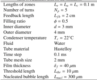
Table 1: Parameters used for the simulation.
Lengths of zones Le= La= Lc=0.1 m Number of turns Np=5 Feedback length Lf b=2 cm Filling ratio φ = 0.5 Inner diameter d =3 mm Outer diameter 4 mm Condenser temperature Tc=22◦C Fluid Water
Tube material Hastelloy
Time step 0.1 ms
Tube mesh size 2 mm
Film thickness δf =40 µm
Threshold length Lthr=10 µm
Nucleated bubble length Lnucl=300 µm
3. Simulation results
One may distinguish different regimes of PHP functioning: start-up, steady oscillations, dry-out. It is well known that there are many internal events occurring in the PHPs. They are re-produced by simulation as described below. CASCO provides management of the following events occurring with vapor bles and liquid plugs: bubble generation, disappearance of bub-bles and plugs, dry spot growth and disappearance. The bubble disappearance occurs according to the assumption 8 when a liq-uid plug overtakes another plug. The vapor pressure grows and fast condensation occurs. A composite long plug forms. Its mass and velocity is determined from the mass and momentum conservation [12]. The bubble is deleted together with all vari-ables associated with it; the current time step is recalculated with a smaller number of equations. Bubbles disappear mainly in the condenser section.
A small plug may also disappear, in two cases. (i) When the plug moves over a dry area, it may spend all its liquid for the film deposition. (ii) When it remains still and there is intense evaporation on its meniscus. However such an event is much less likely.
A typical PHP start-up and functioning is illustrated by Fig.3. The average temperature remains stable within ±1◦C during a long period of time. An insert shows that the start-up lasts less than 5 s.
One of the main results of this study is the absence of the multibranch PHP start-up without bubble generation. Whatever is Pe, the oscillation starts initially but chain bubble coalescence
occurs and, eventually, all the liquid gathers in a single plug; its oscillations decline quickly. This seems to be an effect of the tube heat conduction. When the wall temperature was im-posed and varied stepwise from condenser to evaporator [12], this chain bubble coalescence was observed for a heating power larger than a threshold. However the PHP start-up was possible in the absence of bubble generation for some temperature dif-ferences. The start-up of the single branch PHP is also possible in the heat conducting tube in the absence of bubble genera-tion [16] probably because the average pressure inside PHP is imposed: the single branch PHP has an open end.
24 25 26 27 301 303 305 21 22 23 24 25 26 27 28 29 0 100 200 300 400 500 T e ( °C ) t (s) 22 24 26 28 0 1 2 3 4 5
Figure 3: Time evolution of the averaged over evaporator temperature Te. The
time averaged Tevalue hTei =25.8◦C is shown in red in the inserts. The PHP
thermal resistance calculated with it is 0.14 K/W.
3.1. Start-up and bubble generation
4.794 s 4.674 s 4.640 s 4.622 s x (m) 1.25 1.2
Figure 4: An example of multiple bubble generation in the evaporator of the 9-th branch (2nd from the top in Fig. 1 corresponding to 1.2 m< x < 1.25 m) at Pe=60 W. The color significance is the same as in Fig. 1. Arrows show the
direction of motion of the rightmost liquid plug.
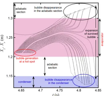
When the bubble generation criterion (assumption 9) is sat-isfied, the bubble generation starts. If the wall is hot enough, many bubbles may be generated one after another at the same hot spot so that “bubble trains” are formed, cf. Fig.4 where the hot spot situates at x ≃ 1.21 m. This event can be seen in Fig. 5 where the time evolution of the left and right ends (Xl,
Xr) of many bubbles is shown for the same case as in Fig.4.
For any particular newly born bubble, one can easily identify the left and right bubble ends in Fig. 5 because they form a di-vergent cusp point at the birth moment (encircled in red). As mentioned before, Xil ≤Xriso the vertical distance between Xri
and Xli curves defines the variable in time bubble length. The plug length (the distance between Xli+1 and Xir) can vary
be-cause of the meniscus phase change and bebe-cause of the liquid film deposition by the receding plug meniscus if the other end advances along the dry wall.
Bubble birth and growth consume the latent heat so the bub-ble generating hot spot eventually cools down and the bubbub-ble generation ends. This is visible in Fig. 5. Right after genera-tion, the velocity of the bubble train coincides with that of the parent plug. After the birth, the bubbles grow in the evapora-tor. The growth of a bubble in evaporator causes compression of the neighboring bubbles and the direction of plug motion can be inverted (cf. Fig.4 for t = 4.794 s). This inversion can be also seen in Fig.5 where the slope of curves (defining the plug velocity) changes its sign. Such an inversion means an
oscilla-Figure 5: Time evolution of bubble end coordinates in the 9th and 10th branches. Each pair of solid lines corresponds to a bubble, i. e. to the temporal variation of its Xland Xr. Each starting (i.e. opening to the right) cusp point
corresponds to the bubble generation at a hot spot. Each ending (i.e. opening to the left) cusp point corresponds to the bubble disappearance.
tion. This shows the mechanism of oscillation sustainment by bubble generation.
Because of the pressure rise discussed above, some of newly created bubbles may disappear (recondense) soon after creation once they reach a cooler condenser or adiabatic section. The bubble disappearance can be identified in Fig. 5 by the lines converging in a cusp (encircled in blue in condenser and in black in adiabatic section).
3.2. PHP dry-out 0 50 100 150 200 250 300 350 400 0 1 2 3 4 5 T e ( °C ) t (s)
Figure 6: Tube wall temperature for Pe =360 W averaged over evaporator:
dry-out dynamics. The images of evaporator are shown for two different times (t = 2 and 4 s) to illustrate the dry area growth dynamics.
The accurate description of dry spots allows us to simulate the complete PHP halt by dry-out that occurs when Peexceeds
a threshold. At a larger Pe, after a short transient, film length
begins to decrease in the evaporator and large dry spots (white areas in the evaporator shown in Fig.6) grow. Within the dry
0 50 100 150 200 250 300 350 0.2 0.25 0.3 0.35 T w ( °C ) x(m) liquid plug condenser adiabatic section evaporator
Figure 7: Temperature distribution along the third PHP branch indicated by an arrow in Fig. 6 for Pe=360 W, t = 4 s. The same image is enlarged above
the curve to indicate the position of film-covered (violet), liquid plug-covered (blue) and dry (white) areas.
spots, the heat transfer is much smaller than within the film-covered area (because of the smaller vapor heat conductivity). High thermal gradients form along the tube (Fig.7) between the dry and film-covered areas in the evaporator. The fast film evaporation in evaporator leads to the pressure rise in all the bubbles located there. This means that all the liquid plugs are expelled almost simultaneously from the evaporator. Such an event causes strong compression of bubbles that situate in con-denser and adiabatic sections. The vapor inside these bubbles condense until their complete disappearance. As a result, all the liquid gathers in the condenser while all the vapor is located in the evaporator. The pressure imbalance between the branches becomes weak which causes a decrease of oscillation ampli-tude. The evaporator temperature grows sharply (cf. Fig.6, after 2.5 s) which makes the film disappearance irreversible.
The dry-out has been already simulated in a different dy-namic film model [14]. However, the authors could not obtain the dry-out with bubble generation. In the present work the dry-out has been obtained with bubble generation, in agreement with numerous PHP experiments where bubble generation is al-ways present.
4. Conclusions
We discuss here a theoretical model and numerical simula-tions of multi-branch PHPs in horizontal orientation (with no gravity influence) including the effects of heat conduction by the tube walls, fluid-tube thermal coupling and bubble genera-tion. It has been found that in the presence of tube heat conduc-tion the PHP start-up is impossible without the bubble genera-tion. The oscillations may start because of initial deviation from equilibrium but they disappear soon because all liquid plugs co-alesce. This behavior is different from the earlier studied case of the imposed evaporator and condenser temperatures with no tube heat conduction where the PHP start-up was possible [12]. In the presence of bubble generation, the oscillations of large amplitude are stable at long times. A mechanism of the oscilla-tion sustainment by the bubble generaoscilla-tion is revealed.
The present simulations can describe the PHP dryout. When the heating power is larger than a threshold, the stable oscilla-tion do not start-up. The liquid films disappear in the evaporator and its temperature rises steeply; the oscillations stop.
Our simulations reproduce at least qualitatively many phys-ical phenomena observed experimentally in transparent PHPs. One needs to perform more detailed studies to make compar-isons with experimental data.
ACKNOWLEDGMENTS
The financial contributions of ANR in the framework of the project AARDECO ANR-12-VPTT-005-02 and of ESA within MAP INWIP are acknowledged. This work was presented at 18th Int. Heat Pipe Conf. and 12th Int. Heat Pipe Symp., Jeju, South Korea, June 12–16, 2016.
References
[1] S. Kim, Y. Zhang, J. Choi, Effects of fluctuations of heat-ing and coolheat-ing section temperatures on performance of a pul-sating heat pipe, Appl. Therm. Eng. 58 (1-2) (2013) 42 – 51, doi:10.1016/j.applthermaleng.2013.03.037.
[2] Y. Zhang, A. Faghri, Advances and Unsolved Issues in Pulsat-ing Heat Pipes, Heat Transfer Eng. 29 (1) (2008) 20 – 44, doi:10.1080/01457630701677114.
[3] S. Khandekar, P. K. Panigrahi, F. Lef`evre, J. Bonjour, Local hydrodynam-ics of flow in a pulsating heat pipe: a review, Frontiers in Heat Pipes 1 (2) (2010) 023003, doi:10.5098/fhp.v1.2.3003.
[4] M. B. Shafii, A. Faghri, Y. Zhang, Thermal Modeling of Unlooped and Looped Pulsating Heat Pipes, J. Heat Transfer 123 (6) (2001) 1159 – 1172, doi:10.1115/1.1409266.
[5] R. T. Dobson, Theoretical and experimental modelling of an open oscil-latory heat pipe including gravity, Int. J. Therm. Sci. 43 (2) (2004) 113 – 119, doi:10.1016/j.ijthermalsci.2003.05.003.
[6] B. Holley, A. Faghri, Analysis of pulsating heat pipe with capillary wick and varying channel diameter, Int. J. Heat Mass Transfer 48 (13) (2005) 2635 – 2651, doi:10.1016/j.ijheatmasstransfer.2005.01.013.
[7] M. Mameli, M. Marengo, S. Zinna, Numerical model of a multi-turn Closed Loop Pulsating Heat Pipe: Effects of the local pressure losses due to meanderings, Int. J. Heat Mass Transfer 55 (4) (2012) 1036 – 1047, doi:10.1016/j.ijheatmasstransfer.2011.10.006.
[8] V. S. Nikolayev, Comment on “Flow and heat transfer of liquid plug and neighboring vapor slugs in a pulsating heat pipe” by Yuan, Qu, & Ma, Int. J. Heat Mass Transfer 54 (9-10) (2011) 2226 – 2227, doi:10.1016/j.ijheatmasstransfer.2011.01.007.
[9] S. P. Das, V. S. Nikolayev, F. Lef`evre, B. Pottier, S. Khandekar, J. Bonjour, Thermally induced two-phase oscillating flow inside a cap-illary tube, Int. J. Heat Mass Transfer 53 (19-20) (2010) 3905 – 3913, doi:10.1016/j.ijheatmasstransfer.2010.05.009.
[10] P. Gully, F. Bonnet, V. Nikolayev, N. Luchier, T. Q. Tran, Evaluation of the vapor thermodynamic state in PHP, in: Proc. 17th Int. Heat Pipe Conf., Begell, ISBN 978-1-56700-453-3, 369 – 376, 2015.
[11] M. Rao, F. Lef`evre, S. Khandekar, J. Bonjour, Understanding transport mechanism of a self-sustained thermally driven oscillating two-phase sys-tem in a capillary tube, Int. J. Heat Mass Transfer 65 (2013) 451 – 459, doi:10.1016/j.ijheatmasstransfer.2013.05.067.
[12] V. S. Nikolayev, A Dynamic Film Model of the Pulsating Heat Pipe, J. Heat Transfer 133 (8) (2011) 081504, doi:10.1115/1.4003759.
[13] R. Senjaya, T. Inoue, Oscillating heat pipe simulation considering ble generation. Part I: Presentation of the model and effects of a bub-ble generation, Int. J. Heat Mass Transfer 60 (0) (2013) 816 – 824, doi:10.1016/j.ijheatmasstransfer.2013.01.059.
[14] R. Senjaya, T. Inoue, Oscillating heat pipe simulation considering dryout phenomena, Heat Mass Transfer 50 (10) (2014) 1429–1441, doi:10.1007/s00231-014-1354-9.
[15] V. S. Nikolayev, Oscillatory instability of the gas-liquid meniscus in a capillary under the imposed temperature
dif-ference, Int. J. Heat Mass Transfer 64 (2013) 313 – 321,
doi:10.1016/j.ijheatmasstransfer.2013.04.043.
[16] V. S. Nikolayev, Effect of tube heat conduction on the single branch pul-sating heat pipe start-up, Int. J. Heat Mass Transfer 95 (2016) 477 – 487, doi:10.1016/j.ijheatmasstransfer.2015.12.016.