Attachment of Polyelectrolyte Multilayers to Cells and the Implications on
Cell Behavior
by
Rosanna Marie Lim
M.S. Chemical Engineering Practice Massachusetts Institute of Technology
B.S. Chemical Engineering University of California, Berkeley
SUBMITTED TO THE DEPARTMENT OF CHEMICAL ENGINEERING IN PARTIAL FULFILLMENT OF THE REQUIREMENTS FOR THE DEGREE OF
DOCTOR OF PHILOSOPHY IN CHEMICAL ENGINEERING PRACTICE at the
MASSACHUSETTS INSTITUTE OF TECHNOLOGY June 2016
02016 Massachusetts Institute of Technology. All rights reserved.
Signature of Author: ... C-C ertified by : ... Certified by: ... At 1 ~A1-~.
~2
;ignature redacted
Department of Chemical Engineering/
/)
June 2016ignature redacted
RobertE. Cohen St. Laurent Professor of Chemical Engineering Thesis Co-S visorSignature redacted
Michael F. Rubner Professor of Materials Science and Engineering Thesis Co-Supervisor
Signature redacted
Y...r ... D... r
Richard D. Braatz Edwin R. Gilliland Professor of Chemical Engineering Chairman, Committee for Graduate Students
MASSACHUSETTS INSTITUTE OF TECHNOLOGY
Attachment of Polyelectrolyte Multilayers to Cells and the Implications on
Cell Behavior
by
Rosanna Marie Lim
Submitted to the Department of Chemical Engineering on April 29, 2016 in partial fulfillment of the requirements for the degree of Doctor of Philosophy in Chemical Engineering Practice
ABSTRACT
The development of targeted drug delivery systems is of fundamental importance for the transport of highly toxic drugs to diseased cells. One way of achieving this is using biohybrid materials, which integrates synthetic components with cells in order to confer unique properties to existing biological systems. An example of this is the cell backpack, which consists of a circular, polymeric patch, microns in diameter and hundreds of nanometers thick, attached to the surface of a cell. Unlike passive delivery systems, cells have the ability to use signaling and trafficking to actively target a disease site. Cells carrying drug-loaded backpacks would thus be able to efficiently carry drugs to unhealthy cells.
The cell backpack material itself is a polymeric patch consisting of stratified layers forming nanostructured compartments. In this thesis, the cell backpack is further developed to improve versatility and drug loading. First, a new, sacrificial thin film is developed to detach the cell backpacks from the substrates that they are fabricated on. This sacrificial multilayer, composed of bovine submaxillary mucin and jacalin lectin, is stable in a wide pH and ionic strength range and dissolves using a chemical stimulus. This mucin/lectin releasable region increases versatility by allowing more materials to be incorporated into the cell backpack, such as drug-containing liposomes. Echogenic liposomes containing doxorubicin were embedded into cell backpacks, and the ability of using these cell backpacks as a targeted, anti-cancer therapy was evaluated by studying the effects on mouse monocytes. Finally, thin films containing maleimide groups were developed for the cell backpacks to covalently attach these polymeric patches to cell surfaces. Former cell surface attachment techniques relied on cell-specific receptors, so covalent attachment would allow backpacks to attach to a greater variety of cells. The advancements investigated in this thesis work help to bring cell
backpack technology one step closer to becoming a viable, therapeutic product.
Thesis Co-Supervisor: Robert E. Cohen
Title: St. Laurent Professor of Chemical Engineering Thesis Co-Supervisor: Michael F. Rubner
ACKNOWLEDGEMENTS
First and foremost, I am grateful to be co-advised by a couple of the most talented researchers at MIT, Professor Robert Cohen and Professor Michael Rubner. I could not have better thesis advisors, and I would like to thank them for their time, guidance, understanding, and continuous support. They have taught me to grow as a researcher and to become more confident in my abilities. Professor Cohen has always been encouraging, even when results were unfavorable, and he would also be happy to give me guidance even when away on sabbatical. I am grateful that he gave me the courage to diverge from my original research plan during several occasions and switch directions to more promising projects. He was also instrumental in creating the PhDCEP program, which is the primary reason I was drawn to graduate school and to MIT. Professor Rubner has always been enthusiastic about the progress of my research, even when my results were unexpected or negative. I am lucky to have worked with someone with such a vast array of knowledge, as he always had new ideas or theories that would keep me passionate about my research.
Secondly, I would also like to acknowledge my thesis committee members, Professor Bradley Olsen and Professor Katharina Ribbeck. Both have been very resourceful and engaging during my thesis committee meetings, providing particularly useful insights for the biological side of my research. I would also like to thank Professor Clayton Radke and Professor Roya Maboudian at the University of California, Berkeley, for their encouragement to apply to graduate school.
During my graduate studies at MIT, I also had the opportunity to participate in the Practice School, where I worked on various projects in industry. Dr. Robert Fisher and Dr. Claude Lupis were excellent station directors at Cabot Corporation and Novartis, respectively. They both pushed me to think and work strategically and to develop professionally.
My research would not have progressed so much without the help of my collaborators. I would like to thank Roberta Polak, a visiting student from the University of Sao Paulo, Brazil. Due to her ideas, I was able to develop my research to include more biological investigations. I would also like to acknowledge Thomas Crouzier, who was a post doctorate researcher in Professor Ribbeck's lab, who helped Roberta and me with our developments. I truly looked up to his methodological way of thinking and eloquent writing style. I would also like to thank Kavya Rakhra from Darrell Irvine's lab, for her useful discussions about cell assays and cell behavior.
In addition to my productive collaborations, the completion of my research would not have been possible without the help and encouragement of my lab members. As the youngest graduate student in the group, I have been able to look up to my colleagues and have been guided by their determination and ability to balance work and life. In particular, I would like to thank Jonathan Gilbert, who helped me get started in the lab. I am grateful for his continuous guidance, patience, and wisdom in helping me with my project. I would also like to thank Hyomin Lee and Siddarth Srinivasan for helping me develop and troubleshoot various parts of my research. Jiyoung Ahn has also been very encouraging, and discussions with her always helped me to remain positive. I am lucky to have an exceptional group of current and former labmates to look up to: Mariana Agostini de Moraes, Jiyoung Ahn, Grinia Nogueira, Dayong Chen, Shreerang Chhatre, Thomas Crouzier, Jonathan Gilbert, Hyewon
Kim, Justin Kleingartner, Hyomin Lee, Kenneth Park, Roberta Polak, Siddarth Srinivasan, and Thiago Taketa. I also had the chance to help a couple undergraduates, Caitlin Sample and Harini Suresh, and I am grateful for this teaching experience.
MIT has also provided me with many resources that have allowed me to complete my research. I would like to thank Tim McClure and Libby Shaw for their expertise in surface analysis instruments at the CMSE. I would also like to thank the equipment stewards at the ISN. I am also grateful to Professor Darrell Irvine and the Irvine lab for allowing me to use their tissue culture and confocal microscope facilities. I also acknowledge the administrative staff in the chemical engineering department and the CMSE, for their support: Suzanne Maguire, Joel Dashnaw, Fran Miles, Katie Lewis, Gwen Wilcox, Alison Martin, Sandra Lopes, Beth Tuths, Andre Puca, Sandra Crawford-Jenkins, Jei Lee Freeman, Dianne Brooks, Susan Rosevear, Susan Dalton, Travis Gray, and Ed Kruzel. Finally, I am also grateful for funding from the CMSE and the Chyn Duog Shiah Memorial Fellowship from MIT.
I am also very blessed to have so many friends and classmates who have enriched my time at MIT. My roommates and best friends, Thomas Willems and Eric Zhu, have seen me grow from my Berkeley years and throughout my time at MIT, and I am so grateful for their patience, constant support in all aspects of life, and humor. Furthermore, my life would be far less colorful without my boys, the "degenerates:" Steven Edgar, Sean Faltermeier, Sean Hunt, William Ho, Lionel Lam, Karthik Narsimhan, David Nicholson, Xiao Su, and Mark Weidman. I am also so lucky to have such a fabulous group of ladies who are constantly there to talk about anything, from intellectual, philosophical topics to random, girly ones: Samantha Collins, Rachel Hoffman, Aanchal Jain, Helen Luo, Anasuya Mandal, Katie Maass, Ankita Mishra, and Lea Poquerusse. Also, I am grateful to have had an intelligent, fun, and simply amazing Practice School crew: Adam Beerman, Lisa Hasenberg, Edwin Khoo, Renee Roesel, Kendele Snodgrass, and Li Tan, among a few others mentioned above. I am also thankful for my friendships with Alex Bourque, Julia Haftel, Jen Lewis, Su Luo, Karthick Murugappan, Ray Smith, and Sue Zanne Tan.
I am also fortunate to have spent two wonderful, fun years at Sloan through the PhDCEP program. A special thank you to my core team, the Caribbean Puffins: Sarah Callaway, Ishan Gokhale, Stefanos Kasselakis, Alex Rakitin, and David Sanchez. I am honored to have worked with my Sloan Women in Management co-presidents, Hailey Crowel and Michelle Travis, and with my MIT Sloan Healthcare and BioInnovations Conference co-chair, Dr. Matija Dreze. I also have an amazing group of travel buddies from my action learning experiences in China and Brazil: Deepti Mutnuru, Ashley Fischer, Jessica Kim, and Ann Levin. I also would like to thank Alaina Pleatman for giving me direction in formulating my capstone chapter. I have had the opportunity to form so many close relationships while at Sloan that I could not possibly name them all here, but I would also like to acknowledge the following people for their friendship and support: David Benjamin, Jian Kang, Lakshmi Kannan, Christa Milley, Valerie Russell, Tory Sheppard, Well Smittinet, Neha Thatte, and Anita Wu.
Finally, I would like to thank my family for their love and for always having faith in me. My parents have always provided me with support and have encouraged me to dream big. I would also like to thank my siblings, Rebecca, Rosalyn, and Jonathan, for believing in
TABLE OF CONTENTS
1. LIST O F FIGURES ... 8
2. LIST OF TA BLES...13
3. INTROD U CTION AN D BA CK GROUN D ... 14
3.1. Introduction...14
3.2. A dvantages of Cell Backpacks ... 17
3.3. Fabrication of Cell Backpacks... 18
3.4. Scope of Thesis...20
3.5. References...22
4. SUGAR-MEDIATED DISASSEMBLY OF MUCIN/LECTIN MULTILAYERS AND THEIR USE AS PH-TOLERANT, ON-DEMAND SACRIFICIAL LAYERS...25
4.1. Introduction...25
4.2. Results and D iscussion ... 28
4.3. Conclusions...36
4.4. Experim ental Section... 36
4.5. References...40
4.6. Supplem entary Inform ation... 44
5. TARGETED ANTI-CANCER DRUG DELIVERY WITH LIPOSOME-LOADED CELL BACKPACKS...53
5.1. Introduction...53
5.2. Results...57
5.3. D iscussion...69
5.4. Conclusions...71
5.5. Experim ental Section... 73
5.6. References...83
5.7. Supplem entary Inform ation ... 86
6. MALEIMIDE MULTILAYERS FOR CELL ATTACHMENT AND BIOMATERIALS APPLICA TION S ... 107
6.1. Introduction...107
6.2. M aleim ide M ultilayers in Cell Backpacks ... 111
6.3. M aleim ide M ultilayers as a Platform for Biom aterials ... 116
6.4. Conclusions...121
6.5. Experim ental Section...121
6.6. References...130
6.7. Supplem entary Inform ation...132
7. CAPSTONE: CORPORATE STRATEGY OF CELL BACKPACKS...143
7.1. Introduction...143
7.2. Strategic Analysis: Porter's Five Forces...145
7.3. Financial Analysis ... 153
7.4. Recom m endations...160
7.5. References...162
7.6. Supplem entary Inform ation...165
8. SU M M ARY AN D FUTURE W ORK ... 166
8.1. Sum m ary...166
8.2. Recom m endations for Future W ork ... 167
1. LIST OF FIGURES
Figure 3-1: Drug distribution in the body. (a) Without targeting agents, drugs circulate throughout the whole body and affect all tissues, both diseased and healthy. (b) Using targeted drug delivery, drugs accumulate at a high concentration at the disease site, leaving healthy cells untouched. (Adapted from Barenholzi)...14 Figure 3-2: Confocal laser scanning microscopy images of cells attached to backpacks. (a)
CH27 B-lymphocyte attached to a cell backpack, fluorescently tagged in green using FITC. (b) and (c) Multiple CH27 B cells, stained in red using Cell-Tracker Red CMPTX, attached to backpacks, stained in green using FITC. (Adapted from Swiston et al .2 )...16
Figure 3-3: (a) Immune cells naturally migrate to tumor cells. (b) The idea of cell backpacks is to use healthy immune cells to carry a drug-loaded polymer patch to the tumor site for targeted, localized drug delivery ... 16 Figure 3-4: Scanning electron microscope images showing that (a) 7 pm backpacks on macrophages are resistant to internalization. (b) However, 6 gm spheres are internalized by the macrophage. (Adapted from Doshi et al.2)...18 Figure 3-5: Steps to fabricate cell backpacks involve photolithography, building multilayers
using layer-by-layer assembly, and cell attachment. ... 18 Figure 3-6: Schematic outlining the layer-by-layer assembly process using polyelectrolytes. A positively charged polymer first adsorbs to the negatively-charged substrate. After subsequent rinsing, a polyanion adsorbs to the polycation, forming thin layer, and the process is repeated to build up the thin film . ... 19 Figure 4-1: Growth curve of (BSM/JAC)n films on glass microscope slides. Thicknesses were m easured by profilom etry (n = 6) ... 28 Figure 4-2: Stability of releasable films in different aqucousnvironments. Fluorescently
labeled (BSMAlexa4
88/JAC-FITC)10 films assembled in a 96-well glass plate were
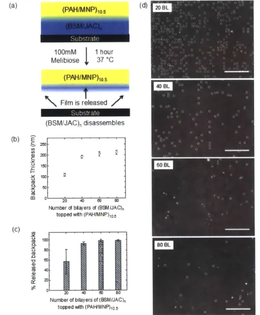
monitored for film stability after incubation for 1 h in different buffered solutions (n = 3 )...3 0 Figure 4-3: (a) Scheme of the cell backpack composition for the release tests (b) Growth curve of final backpack patches topped with (PAH/MNP)10.5 (c) Percentage of
released backpacks and (d) corresponding phase contrast microscope images of slides after incubation in melibiose 100 mM for 1 h at 37 'C and subsequent removal of detached backpacks. Backpack composition: (BSM/JAC)n and (PAH/MNP)IO.5, where n = 20, 40, 60, or 80 BL. All scale bars are 200 jm. Backpacks were 7-10 jm
diameter with 15 jm edge-to-edge spacing on the substrate...32 Figure 4-4: (a) Scheme showing the final backpack composition used for cell attachment
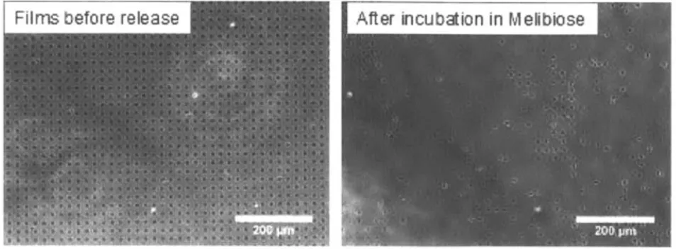
experiments (b) Cell viability of murine monocytes after 1 hour of incubation in PBS buffer (control) or a 100 mM melibiose solution in PBS. The data is reported as the average (n = 10) SD; (c) Monocytes (dyed with a fluorescently green live cell stain) docked onto backpacks (pink) after 1 hour of incubation in PBS (d) Monocytes (green) attached to released backpacks (pink) floating in solution after 1 hour of incubation in 100 mM melibiose. Scale bars are 10 pm...34
Figure 4-5: Bright field microscope images of backpacks floating in solution after 1 hour of incubation in melibiose 100 mM at 37 'C; (a) 60 BL and (b) 80 BL. Scale bars are 50 pim . Arrows indicate the backpacks ... 45
Figure 4-6: Alternative assembly parameters for the releasable system using (BSM/JAC)n multilayers. Images display the backpacks (BPs) before release (left images) and after incubation and release in 100 mM melibiose in PBS (center images). After release the slides were rinsed with DI water and air-dried to observe the remaining backpacks (right images). All films are topped with (PAH/MNP)Io.5. (a) 180 BL of 0.2 mg
mL-of BSM, 150 mM NaCl, (b) 120 BL mL-of 0.4 mg mUl mL-of BSM, 300 mM NaCl. All scale b ars are 50 gm ... 46 Figure 4-7: Growth curve of (BSM/JAC)n films topped with (PAH/MNP)1O. 5 assembled on a
non-patterned glass slide... 47 Figure 4-8: Release test with backpacks built using another BSM provider (Calbiochem). (BSM/JAC)8 0 films topped with (PAH/MNP)10.5 were tested. Images display the
backpacks before release (left image) and after incubation and release in melibiose 100m M in PB S (right im age)...48 Figure 4-9: (a) Stability of (BSMIJAC-FITC)1 bilayer films against pH 9.3 solutions with
different salt concentrations. Films assembled in a 96-well glass plate were monitored for film stability after incubation overnight in different salt concentrations solutions. Solid curve is drawn to guide the eye. (b) Microscope image of backpacks composed of (BSM/JAC)60 + (PAH/MNP)O.5 on the glass slides after 1 hour incubation in water pH 9.3 with 5 mM NaCl. Scale bars are 200 pm...49 Figure 4-10: Sample image of the control sample from the live/dead assay, showing mouse
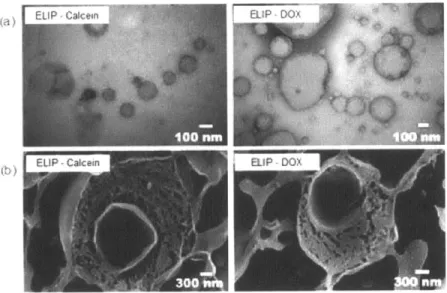
monocytes on the backpacks after 1 hour of incubation in PBS buffer. Live cells are stained in green, and dead cells are stained in red. Most of the backpacks, which can be seen in the bright field, have cells docked onto them. ... 50 Figure 5-1: (a) TEM micrographs of ELIP encapsulating calcein or doxorubicin. (b) Cryo-SEM micrographs of freeze-fractured vesicles loaded with calcein or doxorubicin...57 Figure 5-2: Representative FRAP images of the (a) (PAH/PAA) and (b) (PDAC/SPS) systems containing two ELIP interlayers, which are schematically shown to the left. Empty fluorescently-labeled ELIPs (NBD-PC) were used. Tests were carried out in PBS buffer, and films were imaged at time zero, immediately after photobleaching, and after 30 m inutes... 60 Figure 5-3: (a) Final backpack composition for attachment to monocytes; (b) Representative confocal microscope images of ELIP-DOX backpacks attached to monocytes. The green fluorescence is due to the fluorescently labeled phospholipids (NBD-PC) embedded into the liposomes, and the red fluorescence is due to fluorescently-labeled NeutrAvidin in the attachment region (DyLight 550). ... 61
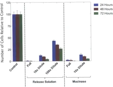
Figure 5-4: Results of the proliferation assay for mouse monocytes exposed to mucinase enzyme and the mucinase/melibiose release solution at various dilutions for 1 hour. The data is normalized to the number of control cells. The assay was carried out using an alamarBlue dye using time points at 24, 48, and 72 hours. ... 63 Figure 5-5: Results of the proliferation assay for mouse monocytes attached to blank ELIP and empty cell backpacks (BP) that have been rinsed one, two, or three times. The data is normalized to the number of control cells. The assay was carried out using an
Figure 5-6: Results of the proliferation assay for mouse monocytes attached to blank ELIP backpacks (BP), empty backpacks, and traditional backpacks that have been rinsed twice. The data is normalized to the number of control cells. The assay was carried out using an alamarBlue dye using time points at 24, 48, and 72 hours...65 Figure 5-7: Doxorubicin release profile from PDAC/SPS pH 3.5 films containing two
ELIP-DOX interlayers. The fluorescence was measured using a plate reader after adding 1% (v/v) Triton X- 100 to rupture the liposomes... 67 Figure 5-8: Total DOX concentration extracted from (PDAC/SPS) pH 3.5 films containing two ELIP-DOX interlayers after releasing drug into solution for 25 days...68 Figure 5-9: Results of the proliferation assay for mouse monocytes attached to DOX ELIP
backpacks (BP), blank ELIP backpacks, and empty backpacks that have been rinsed twice. The data is normalized to the number of control cells. The assay was carried out using an alamarBlue dye using time points at 24, 48, and 72 hours...69 Figure 5-10: Structural formula of phospholipids used in the liposomal formulation: (a)
EggPC, (b) DPPE, (c) DPPG, (d) cholesterol, and (e) NBD-PC...86 Figure 5-11: Particle size distribution and concentration of particles obtained through NTA.
... 8 7 Figure 5-12: Structural formulas of the polycations (a) PDAC: poly(diallyldimethylammonium chloride), (b) PAH: poly(allylamine hydrochloride), and polyanions (c) SPS: poly(styrene sulfonate), (d) PAA: poly(acrylic acid)...87 Figure 5-13: TEM protocol used to observe ELIP adhesion to multilayer films...88 Figure 5-14: (a) TEM micrographs showing the multilayer films before (left images -control)
and after incubation with ELIP and rinsed in TRIS buffer (right images). (b) Images of representative contact angle measurements of the multilayer systems before (left images -control) and after incubation with ELIP (right images). ... 90 Figure 5-15: Representative QCM-D plots showing adsorption of ELIP onto PEM-coated
SO-2 Sulrfac.s. (a) SO-2 crysta1 UkatdL WIth1 ( ACPS ;(bSi2 Crysta Ioe with (PAH/PAA)5.5. Changes in resonance frequency (Af, red lines and left vertical
axis) and energy dissipation (AD, blue lines, right vertical axis) for ELIP adsorption are sh ow n ... 92 Figure 5-16: Cryo-SEM/FIB micrographs of PAH/PAA (top images) and PDAC/SPS (bottom
images) films, both with and without a layer of liposomes. ... 93 Figure 5-17: FRAP representative images of (I) PAH/PAA pH 4.5 and (II) PDAC/SPS pH 3.5 systems containing two ELIP interlayers: (a) after sonication in acetone for 1 minute, and (b) after sonication in etanol for 1 minute. Empty, fluorescently-labeled ELIP were used (NBD-PC). Tests were carried out in PBS buffer, and samples were monitored at time zero, immediately after photobleaching, 10 minutes, and 30 m in utes...94
Figure 5-18: Metabolic activity assay results comparing control cells (which have been handled like the cells with backpacks) to cells directly taken from their flask of growth media. (a) No differences between cells from the flask and the control cells (b) Situation where the cells from the flask proliferated more than the control cells. ... 95 Figure 5-19: Metabolic activity assay results over 72 hours comparing control cells to
monocytes in a solution of either DOX liposomes or blank liposomes. A schematic of the conditions is show n to the left... 98
Figure 5-20: Metabolic activity assay results comparing control cells to monocytes in (a) IgG -biotin and (b) Jacalin lectin ... 99 Figure 5-21: Doxorubicin release profile from PAH/PAA pH 4.5 films containing two ELIP-DOX interlayers. The fluorescence was measured using a plate reader after adding 1% (v/v) Triton X -100 to rupture liposom es...100 Figure 5-22: Total DOX concentration extracted from (PAH/PAA) pH 4.5 films containing
two ELIP-DOX interlayers after releasing drug into solution for 25 days...101 Figure 5-23: DOX dose response curve and IC5 0 for WEHI 265.1 mouse monocytes at 48
h o u rs...10 3 Figure 5-24: Metabolic activity assay results comparing control cells to monocytes in two different concentrations of DOX: 0.2 ptM, the IC50 value at 48 hours, and 0.2 nM, the bulk concentration of DOX eluting from the cell backpacks. ... 104 Figure 6-1: Schematics illustrating different methods for backpack attachment to cells: ligand-receptor attachment using hyaluronic acid, antibody attachment, and covalent attachm ent using m aleim ide groups...107 Figure 6-2: Schematic illustrating the maleimide reaction with a cell surface thiol and the
competing hydrolysis reaction. Chemical groups are not drawn to scale...109 Figure 6-3: Schematic shows the post-functionalization of an assembled multilayer with
su lfo-SM C C ... 110 Figure 6-4: (a) Schematic showing steps for the cell attachment experiment to maleimide surfaces (b) Confocal microscope images showing the cells that settled onto the various multilayers and managed to withstand the rinsing steps. Each film was scratched with an "X" at the center to expose the glass slide, to provide a control for non-specific adsorption. Scale bars are 200 pm. (c) Photographs of the various multilayers assembled on silicon wafers and the corresponding thicknesses of these th in film s...112
Figure 6-5: (a) Confocal microscope images of cells that settled onto patterned films, after the rinsing steps. The patterning of the PEM patches can also be seen in these images. The patches are 15 gm in diameter with 15 gm edge-to-edge spacing. Scale bars are 50 pm. (b) Radial distribution functions that correspond to the microscope images of the patterned cells, indicating the distances (in gm) between a few of the first peaks.
... 1 14 Figure 6-6: Representative confocal microscope images of the cell backpacks attached to mouse monocytes and schematics of their corresponding cell attachment regions... 115 Figure 6-7: Schematic demonstrating how the maleimide multilayer using the
(PAH9.3/SPS9.3) polymer system can be used to attach to the amino acid, cysteine, antibodies, and carbon nanotubes...117 Figure 6-8: High resolution XPS depth profiling spectra of the S2p region for the (a) control
film, (PAH9.3/SPS9.3) 40.5; (b) maleimide film, (PAH9.3/SPS9.3)40.5 + sulfo-SMCC;
and (c) cysteine film, (PAH9.3/SPS9.3) 40 5 + sulfo-SMCC + cysteine. In all the depth
profiles, the surface is the front spectrum, and spectra behind it go progressively deeper into the film. (d) High resolution XPS spectrum of the S2p region for the cysteine film, but just at the surface. The areas under the SPS peak at 168 eV and cysteine peak at 164 eV are show n...118
Figure 6-9: FTIR spectra acquired in ATR mode for the (PAH9.3/SPS9.3) 40.5 base multilayer,
the cysteine film functionalized in PBS buffer at pH 7.4, and the cysteine film functionalized in 50 mM MES buffer at pH 7.4...120 Figure 6-10: High resolution S2p depth profiling spectra of (a) the base multilayer,
(PAH9.3/SPS9.3)40.5 and (b) the base multilayer incubated with cysteine overnight.
... 13 2 Figure 6-11: Atomic composition of sulfur for the (PAH9.3/SPS9.3)40 5 multilayer reacted
w ith m aleim ide...135
Figure 6-12: Atomic composition of sulfur for the maleimide-modified (PAH9.3/SPS9.3) 40.5
multilayer reacted with cysteine. The plot shows the total composition of sulfur as well as the percentage of sulfur exclusively form cysteine. ... 137 Figure 6-13: Schematic showing how the goat anti-rabbit IgG antibody can be immobilized onto a maleimide film. This antibody would be detected with a fluorescent antibody, rabbit IgG labeled w ith Dylight 488. ... 138 Figure 6-14: Schematic illustrating the two methods of thiolating antibodies and attaching them to the maleimide multilayer platform. (a) Antibodies are thiolated using Traut's reagent, which effectively turns amine groups into thiol groups, thus adding sulfhydryls to the antibody. (b) Antibodies are partially reduced using 2-MEA, which reduces the disulfide bridges in the hinge region of the IgG to produce half antibodies. ... 1 3 8 Figure 6-15: Schematic showing how thiolated carbon nanotubes can be immobilized into a m aleim ide m ultilayer. ... 140 Figure 7-1: Summary of Porter's five forces analysis for cell backpack cancer therapy ... 152
2. LIST OF TABLES
Table 4-1: Different assembly parameters tested for (BSM/JAC) films and their corresponding thickness per bilayer (BL), assuming linear growth. Jacalin
concentration was kept constant for all samples (0.1 mg mL-1). ... 44
Table 4-2: Different assembly parameters tested for (BSM/JAC) films when used as a sacrificial film and their corresponding thicknesses. All backpacks are topped with (PA H
/M
N P)10.
5 ... . .. . . .. . . .. . . .. . . .. . . .. . . 46Table 5-1: Interaction of PEMs at different pHs of assembly with liposomes. Unless otherwise indicated, each PEM system was assembled with 0.1 M NaCl in the polymer solutions, and no salt added in rinse solutions. Liposomes were incubated in 10 mM TRIS buffer with 15 mM NaCl at pH 7.4. ... 88
Table 6-1: Dry thickness, swollen thickness, and swelling % of the (PAH9.3/SPS9.3)40.5 films in various buffers, as measured by spectroscopic ellipsometry. The pH of all the buffer solutions w as pH 7.4...119
Table 6-2: Number of elements for a repeating unit in PAH and SPS polymers. ... 133
Table 6-3: Number of elements for a repeating unit in PAH, SPS, and PAH modified with m aleim ide...134
Table 6-4: Number of elements for a repeating unit in PAH-maleimide, PAH-maleimide-cysteine, and SPS. PAH is omitted because it is assumed that all the PAH at the surface is m odified w ith m aleim ide...136
Table 7-1: Estim ated expenses of clinical trials16... . .. . . .. . . .. . . .. . . . .154
Table 7-2: Material costs of producing a cell backpack therapy for each patient ... 156
Table 7-3: List of comparable drugs to cell backpacks and their prices...158
Table 7-4: Profitability analysis for cell backpacks on a per patient basis ... 160
Table 7-5: List of costs of materials used to produce echogenic liposome DOX cell backpacks for the cell backpack therapy ... 165
3. INTRODUCTION AND BACKGROUND 3.1. Introduction
Although there are a variety of drugs available to treat disease, one major challenge in many therapies is making drugs target the particular disease site. When drugs are normally injected into the body, they can circulate throughout the whole body and affect both diseased and normal cells' (Figure 3-la). This means that for a person with lung cancer, for example, a high concentration of chemotherapeutic would be necessary for a therapeutic dosage to accumulate at the tumor site. Furthermore, the chemotherapeutic would also kill off healthy cells.
(a) (b)
Figure 3-1: Drug distribution in the body. (a) Without targeting agents, drugs circulate throughout the whole body and affect all tissues, both diseased and healthy. (b) Using targeted drug delivery, drugs accumulate at a high concentration at the disease site, leaving healthy cells
untouched. (Adapted from Barenholz')
Instead, drugs need to selectively target disease sites for effective treatment. This would allow most of the drug to accumulate in the desired tissues, leaving healthy cells unharmed (Figure 3-1b). The targeting of diseased tissues can be achieved by engineering biomaterials for targeting disease sites and locally releasing drugs.
Recent materials research has focused on the development of biocompatible materials for treatments and therapies, like the use of microparticles,2-5 biocompatible coatings,6-8 and degradable polymers4'9 for drug delivery and imaging. Liposomes, for example, are versatile
materials that can hold both hydrophobic and hydrophilic drugs and display targeting ligands on their exterior.10 Likewise, much research also focuses on biological solutions to health issues, such as gene therapy" or antibody therapies,1 2 1 3 which have already been commercialized for use. Although both approaches have made significant advances over recent years, there is still a rich field to be explored by synergistically combining the two methodologies. These types of systems are termed biohybrid materials, and they integrate synthetic materials with biological systems in order to confer unique properties to existing biological functions. This class of materials can be used in a variety of applications, such as sensing, drug delivery, or biological imaging.14 Cells, in particular, have unique functions and homing capabilities that can be further augmented with synthetic modifications. 5",6 Unlike targeting liposomes or antibodies, which would passively accumulate at unhealthy tissues, cells can use trafficking and signaling to actively target diseased cells. Drugs have been loaded into red blood cells because they remain in circulation for long periods of time and can thus sustain prolonged release of drug in the body.171"8 Furthermore, nanoparticle drugs have also been loaded into macrophages for targeted delivery.9,20
Recently, a new type of cell-based therapy has been explored where cell surfaces are modified to conjugate targeting ligands or drug-laden nanoparticles,5',21 conferring new properties to the cells while minimizing effects on cell function.
One type of biohybrid material involving modification of the cell surface is the cell backpack, which incorporates polyelectrolyte multilayer (PEM) patches with cells. These PEM patches are hundreds of nanometers thick and a few microns wide and attach to part of
22-24
.-25 pm
Figure 3-2: Confocal laser scanning microscopy images of cells attached to backpacks. (a) CH27 B-lymphocyte attached to a cell backpack, fluorescently tagged in green using FITC. (b) and (c)
Multiple CH27 B cells, stained in red using Cell-Tracker Red CMPTX, attached to backpacks, stained in green using FITC. (Adapted from Swiston et al.2 2
)
The cells can thus carry backpacks that hold cargoes, such as drugs, nanoparticles, or labeling moieties. Considering the numerous materials that the patches can carry, cell backpacks are a versatile method of modifying cell surfaces and have a variety of potential applications. Cell backpacks could also hold imaging agents for use in bioimaging or sensing.14,
25
,26
Furthermore, cell backpacks could be used for efficient targeting of tumor or disease sites, followed by controlled release of drugs or vaccines.24 Many immune cells naturally migrate towards sites of tumors or inflammation, so the cell backpack concept is to attach backpacks to the surfaces of cells and have the cells actively target and migrate toward the diseased tissues, as pictured in Figure 3-3.
(a
(b
00
_ _)= C
Healthy immune cells Tumor Cells
w0
Healthy immune cells Tumor Cells
with backpacks
Figure 3-3: (a) Immune cells naturally migrate to tumor cells. (b) The idea of cell backpacks is to use healthy immune cells to carry a drug-loaded polymer patch to the tumor site for targeted,
localized drug delivery.
3.2. Advantages of Cell Backpacks
There are many types of biohybrid materials that can be fabricated using cells, and the cell backpack has many unique properties. For one, cell backpacks provide versatility in the types of materials they can carry, since the PEMs can be modified to hold a variety of cargoes.
One important consideration in cell surface modification is that the cell needs to retain its regular activities and functions after altering the cell surface. Cells communicate with their environment through their membrane proteins and receptors, so it is integral that cells maintain their key functions. The benefit of using cell backpacks is that the PEM patch only covers a portion of the cell rather than the whole cell surface. This ensures that there is still surface area, uncovered by the backpack, which provides sufficient interaction between the cell and the environment. Previous studies have shown that the backpacks are not toxic to the cell and that cells can still perform their basic functions when attached to a backpack. 4 Since the backpacks do not seem to adversely affect cell viability or function, they are a promising route in the development of biohybrid materials.
Furthermore, the stability of the synthetic material on the cell surface needs to be considered, as the material should not be easily shed or internalized. Cell surface modification could prove challenging for phagocytic cells, for example, since the patch or particle intended to remain attached to the surface could be internalized by the cell. In fact, this is the case when spherical nanoparticles and microparticles covalently attach to the surface of phagocytic cells. 4 However, the aspect ratio of the backpacks renders them resistant to internalization, which is not observed for spheres attached to the surface.2 4,27,2 8 Figure 3-4 shows a backpack sitting on the surface of a macrophage, while spheres of similar
diameter are internalized by the same type of cell. Thus, another motivation to further explore cellular backpacks is their ability to remain on the surface of phagocytic cells.
Figure 3-4: Scanning electron microscope images showing that (a) 7 pm backpacks on macrophages are resistant to internalization. (b) However, 6 pm spheres are internalized by the
macrophage. (Adapted from Doshi et al.2 4
)
3.3. Fabrication of Cell Backpacks
Cellular backpacks are polymeric patches attached to cell that can be introduced into the body that is both biological and are synthesized through a combination of photolithography assembly. A schematic of backpack fabrication and attachment is
surfaces to create a material synthetic. These backpacks and layer-by-layer (LbL) shown in Figure 3-5.
Glass SlIde Cell Attachment Region Payload Region
Spin-Coat Release Region
Photoresist
Glass Slide --
Dissolve
UV Mask and Release s
Photoresist I Region
Development Side View of Circular
Glass Slide Backpacks on the Glass Slide
4Collect
Glass Slide kak Laye-by-Backpacks jLayer-by-Layer Assembly Attach Backpacks to Cells RemoveGlass Slide Photoresist
Figure 3-5: Steps to fabricate cell backpacks involve photolithography, building multilayers using layer-by-layer assembly, and cell attachment.
The first step in creating cell backpacks is photolithography, to create the micron-sized patch patterns on a surface. A glass slide is coated with photoresist and then patterned using ultraviolet light. The next step of the backpack fabrication process is building polyelectrolyte multilayers using LbL assembly, first pioneered by Decher.2 9 In LbL assembly, a substrate is immersed in a solution of a polycation or a polyanion, which adsorbs and forms a thin layer on the surface, schematically illustrated in Figure 3-6.
+ Rinse - Rinse Etc.
Polycation Polyanion Polycation
Solution Solution Solution
o
~
a, )Etc.
Figure 3-6: Schematic outlining the layer-by-layer assembly process using polyelectrolytes. A positively charged polymer first adsorbs to the negatively-charged substrate. After subsequent rinsing, a polyanion adsorbs to the polycation, forming thin layer, and the process is repeated to
build up the thin film.
After rinsing, the surface is immersed into another polymer solution of the opposite charge, which adsorbs to the first layer, forming a thin film. The process is repeated until the desired multilayer thickness is achieved. The first LbL-assembled multilayers were made with polyelectrolytes," but multilayers have been developed to include hydrogen-bonding polymers,1 -32 nanoparticles,"3 biopolymers,34,35 enzymes,36 and carbon nanotubes.37,38 In
addition to the types of polymers or molecules used, the solution pH is an important factor in determining the growth rate and behavior of PEMs. since the pH influences the degree of ionization of particular side groups.39A0
The resulting PEMs are ultrathin films of polymers and can bind through electrostatic interactions, hydrogen bonding, or other interactions. The cell backpacks have three regions of stacked PEMs, as pictured in Figure 3-5. The first part is the release region, which is used to build the patches on a substrate and will eventually be degraded to release the backpacks from the surface. The key characteristic of the release region is the ability to control the degradation of these multilayers using environmental stimuli. More specifically, this region would need to be able to remain attached to the substrate while the remaining regions are assembled. Hydrogen-bonding sacrificial LbL films have typically been used for this region. The next layer is a payload region(s), which can carry drugs, enzymes, or other desired moieties for incorporation into this cell backpack system. The payload region allows for greater flexibility in polyelectrolyte choice, since the polymers incorporated into this PEM depend on the type of payload introduced to the body. Fluorescent labels can also be integrated in this region so that microscopic methods can be used to detect successful attachment of a backpack to a cell. The final layer is the cell adhesive region, which contains polymers, proLtIN, orUI Ur chmILdL nMiUieIs that attach to cel KCan suriaces. Once all
regions are assembled, the photoresist is dissolved to obtain the circular patches on the substrate, which are about 7-10 gm in diameter and a few hundred nanometers thick. The release region is then degraded to release the backpacks into solution for attachment to cells.
3.4. Scope of Thesis
This thesis further develops the cell backpack as a drug delivery vehicle that can eventually be used to treat patients. Each chapter details advancements for one of the regions of the cell backpack, but it also outlines the relevance in applications outside the scope of cell backpacks and drug delivery.
Chapter 4 describes a new release region for the cell backpack. Although the former hydrogen-bonding regions worked effectively, they have a critical pH of about 6.4 and dissolve in neutral and basic solutions. This means that LbL assembly for the payload and cell attachment regions cannot be performed in a neutral or basic pH range. Many therapeutic molecules, such as proteins or colloidal particles, cannot sustain the acidic pH required to stabilize the hydrogen-bonding release layers, thus precluding many useful materials from being incorporated into the cell backpack. To overcome this limitation, a sacrificial thin film system is developed that can remain stable over a wide pH range and at high ionic strength. The film was created through LbL assembly of bovine submaxillary mucin (BSM) and the lectin jacalin (JAC), building a (BSM/JAC) multilayer system. The film would dissolve using a chemical trigger instead of a pH stimulus, thus allowing for subsequent LbL assembly of additional films in a variety of conditions. This sacrificial multilayer was then used for the cell backpacks and attached to mouse monocytes to access cellular compatibility.
The development of the new release region diversifies the types of materials that can be incorporated into the cell backpack. In particular, drug-containing liposomes can now be embedded into these PEM patches. Chapter 5 details a targeted anti-cancer drug delivery technique using liposome-loaded cell backpacks, which is the first time toxic drugs have been incorporated into the payload region. Doxorubicin (DOX) is encapsulated in echogenic liposomes, which contain air pockets that can later be exploited for localized delivery in vivo using ultrasound. The liposomes are then embedded into the cell backpack, and the drug release properties and resulting cell behavior are investigated.
Finally, Chapter 6 delves into the cell attachment region of the backpack, where a covalent attachment method is developed. The cell attachment methods formerly developed for the cell backpacks include the use of biopolymers and antibodies to attach to cell surface
variety of cells used, so a more versatile attachment method is investigated. Maleimide groups are incorporated into the cell attachment region to covalently react to thiol groups on cell surface proteins. In addition to the cell attachment region of the cell backpack, maleimide groups in a PEM film can also be used to react with other thiolated molecules, thus making this maleimide multilayer a platform for other biomaterial applications.
Chapter 7 is a capstone chapter that ties together the technical aspects and potential of the cell backpack with business considerations. It is a corporate strategy analysis from the perspective of an established biotechnology firm to see if it would be strategically favorable to acquire cell backpack technology. This thesis concludes with some future directions for developing cell backpacks in the laboratory and how they can eventually be used therapeutically.
3.5. References
(1) Barenholz, Y. Nat. Nanotechnol. 2012, 7, 483-4.
(2) Yan, Y.; Johnston, A.; Dodds, S. ACSNano 2010, 4, 2928-2936. (3) Ochs, C.; Such, G.; Yan, Y. A CS Nano 2010, 4, 1653-1663.
(4) Paramonov, S. E.; Bachelder, E. M.; Beaudette, T. T.; Standley, S. M.; Lee, C. C.; Dashe, J.; Frdchet, J. M. J. Bioconjug. Chem. 2008, 19, 911-9.
(5) Broaders, K. E.; Pastine, S. J.; Grandhe, S.; Frechet, J. M. J. Chem. Commun. 2011,
47, 665-7.
(6) Lynge, M. E.; Laursen, M. B.; Hosta-Rigau, L.; Jensen, B. E. B.; Ogaki, R.; Smith, A. a a; Zelikin, A. N.; Stadler, B. ACS Appl. Mater. Interfaces 2013, 5, 2967-75.
(7) Castleberry, S.; Wang, M.; Hammond, P. T. ACSNano 2013, 7, 5251-61. (8) Crouzier, T.; Ren, K.; Nicolas, C.; Roy, C.; Picart, C. Small 2009, 5, 598-608. (9) Broaders, K. E.; Grandhe, S.; Frdchet, J. M. J. J. Am. Chem. Soc. 2011, 133, 756-8.
(10) Noble, G. T.; Stefanick, J. F.; Ashley, J. D.; Kiziltepe, T.; Bilgicer, B. Trends Biotechnol. 2014, 32, 32-45.
(11) Manfredsson, F. P.; Bloom, D. C.; Mandel, R. J. Neurobiol. Dis. 2012, 48, 212-21. (12) Jaracz, S.; Chen, J.; Kuznetsova, L. V; Ojima, I. Bioorg. Med. Chem. 2005, 13,
5043-54.
(13) Panowksi, S.; Bhakta, S.; Raab, H.; Polakis, P.; Junutula, J. R. MAbs 2014, 6, 34-45. (14) Zhao, W.; Sock Leng Teo, G.; Kumar, N.; Karp, J. M. Mater. Today 2010, 13, 14-21.
(15) Stephan, M. T.; Irvine, D. J. Nano Today 2011, 6, 309-325.
(16) Pierig, F.; Serafini, S.; Rossi, L.; Magnani, M. Adv. Drug Deliv. Rev. 2008, 60,
286-95.
(17) Rossi, L.; Serafini, S.; Pierig6, F.; Antonelli, A.; Cerasi, A.; Fratemale, A.; Chiarantini, L.; Magnani, M. Expert Opin. Drug Deliv. 2005, 2, 311-22.
(18) Millin, C. G.; Marinero, M. L. S.; Castafieda, A. Z.; Lanao, J. M. J. Control. Release 2004, 95, 27-49.
(19) Gorantla, S.; Dou, H.; Boska, M.; Destache, C. J.; Nelson, J.; Poluektova, L.; Rabinow, B. E.; Gendelman, H. E.; Mosley, R. L. J. Leukoc. Biol. 2006, 80,
1165-1174.
(20) Dou, H.; Destache, C. J.; Morehead, J. R.; Mosley, R. L.; Boska, M. D.; Kingsley, J.; Gorantla, S.; Poluektova, L.; Nelson, J. A.; Chaubal, M.; Werling, J.; Kipp, J.; Rabinow, B. E.; Gendelman, H. E. Blood 2006, 108, 2827-2835.
(21) Stephan, M. T.; Moon, J. J.; Um, S. H.; Bershteyn, A.; Irvine, D. J. Nat. Med. 2010,
16, 1035-41.
(22) Swiston, A. J.; Cheng, C.; Urn, S. H.; Irvine, D. J.; Cohen, R. E.; Rubner, M. F. Nano Lett. 2008, 8, 4446-53.
(23) Swiston, A. J.; Gilbert, J. B.; Irvine, D. J.; Cohen, R. E.; Rubner, M. F.
Biomacromolecules 2010, 11, 1826-32.
(24) Doshi, N.; Swiston, A. J.; Gilbert, J. B.; Alcaraz, M. L.; Cohen, R. E.; Rubner, M. F.; Mitragotri, S. Adv. Mater. 2011, 23, H105-9.
(25) Zhao, W.; Schafer, S.; Choi, J.; Yamanaka, Y. J.; Lombardi, M. L.; Bose, S.; Carlson, A. L.; Phillips, J. a; Teo, W.; Droujinine, I. a; Cui, C. H.; Jain, R. K.; Lammerding, J.; Love, J. C.; Lin, C. P.; Sarkar, D.; Kamik, R.; Karp, J. M. Nat. Nanotechnol. 2011, 6, 524-31.
(26) Prescher, J. a; Bertozzi, C. R. Nat. Chem. Biol. 2005,1, 13-21.
(27) Champion, J. a; Mitragotri, S. Proc. Natl. Acad Sci. 2006, 103, 4930-4. (28) Mitragotri, S.; Lahann, J. Nat. Mater. 2009, 8, 15-23.
(29) Decher, G. Science (80-.). 1997, 277, 1232-1237.
(30) Kharlampieva, E.; Sukhishvili, S. Polym. Rev. 2006, 46, 377-395.
(31) Kharlampieva, E.; Kozlovskaya, V.; Sukhishvili, S. a. Adv. Mater. 2009, 21, 3053-3065.
(32) Lee, H.; Mensire, R.; Cohen, R. E.; Rubner, M. F. Macromolecules 2012, 45, 347-355. (33) Lee, D.; Rubner, M. F.; Cohen, R. E. Nano Lett. 2006, 6, 2305-12.
(34) Croll, T. I.; O'Connor, A. J.; Stevens, G. W.; Cooper-White, J. J. Biomacromolecules 2006, 7, 1610-22.
(35) Crouzier, T.; Beckwitt, C. H.; Ribbeck, K. Biomacromolecules 2012, 13, 3401-8.
(36) Lvov, Y.; Ariga, K.; Ichinose, I.; Kunitake, T. J. Am. Chem. Soc. 1995, 117, 6117-6123.
(37) Mamedov, A. a; Kotov, N. a; Prato, M.; Guldi, D. M.; Wicksted, J. P.; Hirsch, A. Nat. Mater. 2002, 1, 190-4.
(38) Zhang, M.; Su, L.; Mao, L. Carbon N. Y. 2006, 44, 276-283.
(39) Lichter, J. a.; Van Vliet, K. J.; Rubner, M. F. Macromolecules 2009, 42, 8573-8586. (40) Choi, J.; Rubner, M. F. Macromolecules 2005, 38, 116-124.
4. SUGAR-MEDIATED DISASSEMBLY OF MUCIN/LECTIN MUIJLTILAYERS AND THEIR USE AS PH-TOLERANT, ON-DEMAND SACRIFICIAL LAYERS [This chapter is partially reproduced from "Polak, Roberta; Crouzier, Thomas; Lim, Rosanna M.; Ribbeck, Katharina; Beppu, Marisa M.; Pitombo, Ronaldo N.M.; Cohen, Robert E.; Rubner, Michael F. Biomacromolecules 2014, 15, 3093-8.]
A new and more versatile release region for the cell backpack is first investigated in order to allow for more flexibility and to open more opportunities for developing the payload and cell attachment regions.
4.1. Introduction
The generation of thin films that can be disassembled using a specific triggering mechanism has been widely investigated and is now applied to many useful purposes. In addition, the versatility of the layer-by-layer (LbL) assembly methodology has opened a wide range of triggering mechanisms and applications for such sacrificial films. LbL films have been designed to trigger the release of drugs, small molecules, or other thin films, which has proven to be useful for controlled drug delivery and biomimetic materials applications. -6 In stratified film structures, a bottom sacrificial multilayer film can be selectively dissolved, thereby releasing the more stable parts of the film from the substrate.1' 7-17 These so-called free-standing films have found uses in a wide range of applications, from optics to biomedical purposes.18-21 Hydrogen-bonded LbL multilayer systems have been extensively used as sacrificial layers since they are typically stable at low pH and dissolve at higher pH. One system, composed of poly(methacrylic) acid and poly(vinylpyrrolidone), relies on hydrogen bonds formed between carboxylic acids and carbonyls that can be disrupted above pH 5.6. An alternative hydrogen bonding system based on poly(methacrylic acid) and
the loading of therapeutic molecules such as proteins will often not sustain the acidic pH required to maintain stability of hydrogen-bonding release layers, thereby limiting their biomedical applicability. Alternative triggering mechanisms that do not depend on pH change have also been reported. Some examples include the use of irradiation (light-triggered release), which can damage DNA; the use of reducing agents on disulfide bonds, which can affect the folding of proteins; the use of solvents2 4 which, in some instances, can be toxic
as well as destructive to cells and proteins; the use of water-soluble polymers,2 5 which limits
their downstream application in aqueous environments; and the use amphoteric copolymer films,'7
which selectively dissolves in acidic or in neutral/basic solutions, and narrows their use to a limited pH range.
Enzymes are also capable of disassembling some films or structures.26-29 However, the poor diffusion of the enzyme through the multilayer film to reach the substrate-film interface would limit its usefulness and may introduce a protein to other parts of the film.26-29 Thus, unintended enzymatic degradation, in addition to the particular pH, ionic strength, and divalent ions necessary for enzymatic activity, could destabilize the fims deposited on top of it. Because of the limitations of other approaches, the development of a sacrificial film system that is biocompatible, stable in a wide pH range, but can be specifically triggered with minimal effects on other aspects of the system is of great importance.
We then hypothesized that an alternative to hydrogen-bonded sacrificial films could come from the assembly of mucin and lectin proteins. Mucins are a family of densely 0-glycosylated glycoproteins that are secreted by higher organisms to both lubricate and protect the epithelial cell surfaces from biological, chemical, and mechanical challenges.3 0 Since they
are negatively charged, they can be paired with positively charged polymers for LbL assembly.31-35 Mucins also present sugars, including glucosamine, N-acetyl-d-galactosamine (GalNAc), and sialic acid residues, which function as ligands for various
carbohydrate-binding proteins called lectins.363 8 Thus, as recently demonstrated by the Ribbeck group, mucin/lectin multilayers can be generated on the basis of such interactions, independent of electrostatic pairing of polyelectrolytes.39 This combination resulted in films that were stable in low and high pH as well as high ionic strength. In the presence of a competitive sugar, a portion of the lectins could be released from the film; however, the film remained intact. To overcome this limitation, we developed a new mucin/lectin film that completely disassembles upon exposure to a competitive inhibitor, while remaining stable in low and high pH and high ionic strengths in its absence.
We use bovine submaxillary mucin (BSM) and the lectin jacalin (JAC), a tetrameric protein able to bind the GalNAc moieties40 present in abundance in the BSM sugar chains. We show that they can be successfully assembled into multilayer films using LbL assembly. We also explore the robustness of (BSM/JAC) films in a range of aqueous conditions, including a wide pH range as well as high ionic strength and show that they can be disassembled only in a solution of melibiose sugar. We demonstrate that the films can be employed as sacrificial release layers and determine their biocompatibility in a specific application: the creation of cell backpacks.
Cell backpacks are 7-10 pm diameter polymer patches capable of attaching to cells.4 They have the ability to encapsulate and to release drugs while successfully avoiding phagocytic internalization, remaining on the cell surface with minimal reduction in cell viability.6 The fabrication of these cell backpacks involves polymer film deposition onto a photopatterned array to create a stratified LbL multilayer system containing three regions: a release region, a drug payload region, and a cell adhesive region.4 The development of cell
backpacks has been hampered by the limitations of the hydrogen-bonded release region, which cannot support the further assembly of drug-loading and cell adhesive regions at
films at high pH and allow their release when exposed to melibiose. We also demonstrate that backpacks using the (BSM/JAG) release region can be associated with cells and be released in the presence of melibiose, without any sign of cytotoxicity. This new release system thus proved useful in the cell backpack application, broadening the range of polyelectrolyte assemblies possible on top of the sacrificial region and widening the range of drugs and proteins that can be incorporated into the payload regions of the cell backpack.
4.2. Results and Discussion
4.2.1. (BSMIJAC), Films Grow Linearly
To characterize the growth behavior of the system, (BSM/JAC), films were assembled onto nonpatterned glass slides, where the subscript n refers to the number of bilayers deposited. Figure 4-1 depicts the growth curve for (BSM/JAC)n films through 80 bilayers as assembled from 1.0 mg mL1 of BSM and 0.1 mg mL-1 of jacalin in 300 mM of NaCl, in 20 mM HEPES buffer at pH 7.4.
200 E 150-C UI) w 100 -.0 R2= 0.943 50-0 20 40 60 80
Number of bilayers of (BSM/JAC),
Figure 4-1: Growth curve of (BSM/JAC), films on glass microscope slides. Thicknesses were measured by profilometry (n = 6).
A preliminary investigation of the assembly parameters and film growth that lead to the adoption of these conditions can be found in Section 4.6.1 (Table 4-1). The growth curve has a linear trend, owing to the strong mucin/lectin interactions that suppress diffusion of the components in the already-assembled regions of the growing film. The films were optically clear and smooth, with a roughness of 4-6 nm for the 20, 40, and 60 bilayer (BL) films and 12 3 nm for 80 BL, as measured by profilometry. The linear growth behavior and range of roughness values measured for the (BSM/JAC) film are characteristics similar to another mucin/lectin multilayer system composed of pig gastric mucin and wheat germ agglutinin, which was first explored by Crouzier et al.38
4.2.2. (BSMIJAC) Films Withstand pH and Ionic Strength Variations and are Destabilized by Melibiose
Since the (BSMI/JAC) film is based on specific and multivalent interactions between the lectin and sugar residues,35-37 we hypothesized that this architecture would be stable enough to allow the deposition of additional layers from solutions with a wide range of pH and ionic strengths. To demonstrate these features, we studied the stability of (BSM/JAC)lo films under a variety of pH and ionic strengths by monitoring the amount of fluorescently labeled BSM-Alexa4 8 8 and JAC-FITC before and after treatment (Figure 4-2). Since most applications of sacrificial films require rapid dissolution of the films, we limited the treatment time to 1 h.
100 BSM L) TBM o -E 75-5 0 -E 25 0C) Melibiose in PBS pH 7.4
Figure 4-2: Stability of releasable films in different aqueous environments. Fluorescently labeled (BSM-''x488/,JACII()1o films assembled in a 96-well glass plate were monitored for film
stability after incubation for I h in different buffered solutions (n = 3).
A small Fraction of lectin and mucin is released when the Films are exposed to solutions different from the assembly solution, probably due to the disruption of electrostatic interactions between sone components ofthe film. The (3SM/,IAC)I() film was stable in PBS, serun-containing DMEM, a broad pH1 range (from pH 3 to pH 9). and high ionic strength (up to 5 M NaCL, pH 7). While the high density of multivalent specific interactions between the lectin and mucin sugar residues offers good stability to the Films when challenged with a variety of aqueous environments, exposure to solutions of ielibiose causes significant dissolution of the multilayer film (Figure 4-2). This sugar functions as a competitive inhibitor for the jacalin lectin. destabilizing the intermolecular interactions between BSM and JAC. The remaining fluorescence measured after melibiose treatment is likely due to residual BSM or JAC that has adsorbed to the substrate and could not be removed by bufer washes of the well. The combination of high pH and ionic strength stability and the ability to trigger its dissolution by exposure to melibiose make (BSM/JAC) films ideal candidates as sacrificial films. As such. (BSM/JAC) would have the potential to unlock a wide diversity of potential applications previously inaccessible with other releasable films.
4.2.3. (BSM/JAC)6 0 Can Release (PAH/MNP)10.5 Backpacks
Having established the extended range stability in various aqueous environments and triggerable dissolution behavior of (BSM/JAC) films, we then explored their use as a sacrificial multilayer for the fabrication of cell backpacks. Cell backpack conjugates are biohybrid materials consisting of a polymer patch, hundreds of nanometers thick and microns wide, that can attach to a cell surface.4 6 Adapting a previous methodology developed by our group4 (see Section 4.4 for details), we built a photopatterned array of patches of (BSM/JAC), topped with a magnetic multilayer stack of (poly(allylamine hydrochloride)/magnetic nanoparticles)1o.5, or (PAH/MNP)10., as shown in Figure 4-3a.
(PAH/MNP)IO.5 multilayers are used in the cell backpack system to provide magnetic
manipulation and to create mechanically robust patches5 that do not fold once suspended in solution (Section 4.6.2 Figure 4-5). The final backpacks had a mean diameter of 7-10 ptm with a 15 pLm edge-to-edge spacing on the glass substrate. The measured thicknesses of the backpacks topped with (PAH/MNP)IO.5 are reported in Figure 4-3b, showing that the
backpack film thickness reaches a saturation point at about 60 BL. The same saturation point is also observed when (BSM/JAC), films are topped with (PAH/MNP)10.5 layers on a
nonpatterned glass slide (Section 4.6.4 Figure 4-7). As will be discussed later, diffusion of PAH into the (BSM/JAC) region is likely possible and could alter the growth regime of the thin films, limiting backpack film growth beyond 60 bilayers.
This diffusion-related saturation in growth has an effect on the melibiose-induced release of the cell backpacks. As shown in Figure 4-3c, a critical number of bilayers is necessary for maximal yield of released backpacks. Upon incubation in 100 mM melibiose, the percentage of backpacks released increases as the number of bilayers increases and levels off after 60 BL, consistent with the trend in backpack film growth. In fact, the releasable