Publisher’s version / Version de l'éditeur:
Vous avez des questions? Nous pouvons vous aider. Pour communiquer directement avec un auteur, consultez la première page de la revue dans laquelle son article a été publié afin de trouver ses coordonnées. Si vous n’arrivez pas à les repérer, communiquez avec nous à [email protected].
Questions? Contact the NRC Publications Archive team at
[email protected]. If you wish to email the authors directly, please see the first page of the publication for their contact information.
https://publications-cnrc.canada.ca/fra/droits
L’accès à ce site Web et l’utilisation de son contenu sont assujettis aux conditions présentées dans le site
LISEZ CES CONDITIONS ATTENTIVEMENT AVANT D’UTILISER CE SITE WEB.
Fire Study (National Research Council of Canada. Division of Building Research), 1961-06
READ THESE TERMS AND CONDITIONS CAREFULLY BEFORE USING THIS WEBSITE. https://nrc-publications.canada.ca/eng/copyright
NRC Publications Archive Record / Notice des Archives des publications du CNRC : https://nrc-publications.canada.ca/eng/view/object/?id=9d3bbc1f-6c56-4ce9-8eee-71fdf257d90f https://publications-cnrc.canada.ca/fra/voir/objet/?id=9d3bbc1f-6c56-4ce9-8eee-71fdf257d90f
NRC Publications Archive
Archives des publications du CNRC
For the publisher’s version, please access the DOI link below./ Pour consulter la version de l’éditeur, utilisez le lien DOI ci-dessous.
https://doi.org/10.4224/40001345
Access and use of this website and the material on it are subject to the Terms and Conditions set forth at
Fire test of a 'tri-seal' floor and ceiling assembly Harmathy, T. Z.
TH9111
N27f 5 . G
NATIONAL RESEARCH COUNCIL 'CANADA
D I V I S I O N OF BUILDING RESEARCH
PIRE TEST OF A "TRI-SEAL" FLOOR AND CEILING ASSEMBLY
F i r e Study N o .
5
o f the
D i v i s i o n o f B u i l d i n g R e s e a r c h
OTTAWA
PREFACE
This publication presents t h e r e s u l t s of a t e s t c a r r i e d out by the Division of Building Research of the National Research Council with the use of i t s f i r e research f a c i l i t i e s . The t e s t was c a r r i e d out a t t h e request of t h e i n d u s t r i a l company concerned upon payment of the r e g u l a r t e s t fee. The i n i t i a l r e p o r t was submitted p r i v a t e l y t o t h i s company i n accordance with r e g u l a r DBR/NRC practice.
The t e s t r e s u l t s obtained a r e now published i n t h i s form with the agreement of the sponsor of t h e t e s t so t h a t the information may be a v a i l a b l e f o r general use. This procedure i s unlike t h a t normally followed i n the case of o t h e r t e s t s c a r r i e d out on proprietary products o r construc- t i o n s . It has been adopted i n t h e case of f i r e r e s i s t a n c e t e s t s because of the considerable c o s t of each t e s t which makes it desirable t o eliminate, a s f a r a s possible, the n e c e s s i t y f o r repeating such t e s t s on t h e same o r s i m i l a r constructions. Special care has been taken t o describe a l l the p e r t i n e n t f e a t u r e s of the materials, the construction and the method of t e s t , i n order t o make t h e r e s u l t s a s useful a s possible.
Ottawa
FIRE TEST OF A "TRI-SEAL" FLOOR AND CEILING ASSEh'IBLY
This r e p o r t describes a f i r e t e s t conducted on a "Tri-Seal" f l o o r and c e i l i n g assembly of the Gypsum, Lime
and Alabastine Limited, on November 11, 1959. The t e s t was
requested by t h e Toronto Office of t h e Gypsum, Lime and
Alabastine Limited,
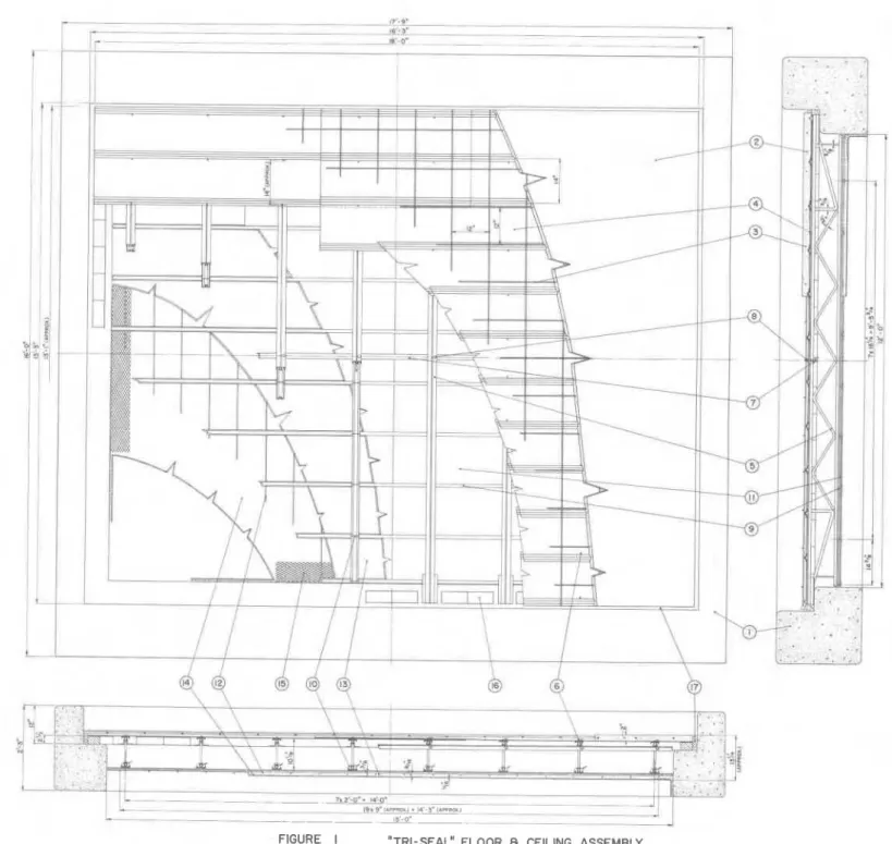
The main s i z e s and a l l construction d e t a i l s of t h e specimen are shown i n Figs. 1 and 2. S p e c i f i c a t i o n of the p a r t s and m a t e r i a l s i s given below. Note t h a t t h e item numbers correspond t o the p a r t numbers i n t h e f i g u r e s .
1. Reinforced. frame, made from r e f r a c t o r y castable supplied
by the Division of Building Research of the National
Research Council.
Concrete s l a b 2 in. t h i c k , made from ready-mixed concrete
of 2500 lb/sq i n . nominal compressive s t r e n g t h , supplied by a l o c a l f i n n . The a c t u a l s t r e n g t h of two specimens taken by B.R.C. p e r s o m e l from two d i f f e r e n t batches during the placement of t h e concrete was found t o be 3300 lb/sq i n . and 2700 lb/sq i n . , r e s p e c t i v e l y , a t 28
days. (The t e s t s were performed on cylinders made i n
conformance t o ASTM C31-49 and loaded according t o ASTM
C39-49.) On t h e day before t h e t e s t the r e l a t i v e
humidity i n the concrete ( a t a distance
13
i n . from t h es u r f a c e ) was found t o be l e s s than 40 per cent.
3. Clipped s t e e l mat, f a b r i c a t e d i n conformance t o ASmI
A184-37 from &in. b i l l e t - s t e e l b a r s (ASTM A15-54T) of s t r u c t u r a l grade, with 12- by 12-in. spactng.
Metal f l o o r forms with inverted V-shaped corrugation along both edges, made by cold pressing from No. 28
gauge high s t r e n g t h low a l l o y cold-rolled s t e e l sheet (ASTM A374-54T), c u t t o 10-ft by approximately 17-in. s i z e s .
"Macomber Allspan" s t e e l f l o o r j o i s t s of 1 2 - f t c l e a r span, conforming t o s i z e No. 210A of Macomber Design Manual MA-59.
I*-in. galvanized roofing n a i l s with 3/8-in. diameter head.
Bridging angle of 1&- by 1&- by 3/16-in. s i z e s , conforming t o A I S I C1020.
&-
by 2-in. hexagonal head b o l t s , with nuts."Tri-Seal Loop Channels", a s shown i n Fig. 3, made from No. 25 gauge galvanized cold-rolled carbon s t e e l s t r i p s , conforming t o temper No. 4 of ASTM A109-49T.
Galvanized double-strand t i e wires of W and M gauge No. 18.
Pieces of perforated gypsum l a t h , with the f i b r e of paper coverings p a r a l l e l t o t h e s h o r t dimension (commonly known a s "Perforated Tri-Seal Lath"), i n 3/8- by 16- by 48-in. dimensions, conforming t o ASTM C37-54.
Cold-drawn s t e e l r e i n f o r c i n g wires of W and M gauge No. 12, conforming t o ASTM A82-34.
Base c o a t , 9/16 i n . t h i c k , made from m i l l aggregated p l a s t e r of a composition of 100 lb n e a t gypsum p l a s t e r and 2.2 cu f t p e r l i t e aggregate.
14. 1/16 i n . f i n i s h c o a t , made from standard lime putty- p l a s t e r of p a r i s mixture.
1 . Ekxpanded metal l a t h i n 12-in. wide s t r i p s , approximately 2.5 lb/sq yd.
16. Red c l a y b r i c k s and mortar. 17. Asbestos wool.
A s may be seen from Fig. 1, t h e edges of the
specimen were simply supported. A clearance of 1 t o 13 in. w a s l e f t between the reinforced frame and t h e edges i n order t o eliminate any r e s t r a i n i n g f o r c e s r e s u l t i n g from h o r i z o n t a l thermal expansion of t h e specimen during t h e t e s t . The gap around t h e edges was f i l l e d with loosely packed asbestos wool.
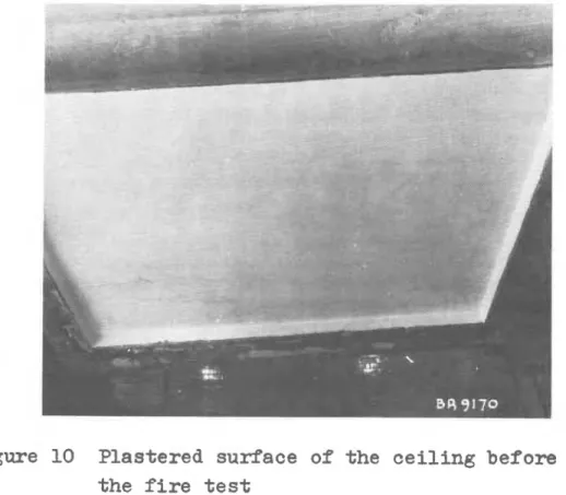
The plastered surface of the c e i l i n g immediately before the t e s t i s shown i n Fig. 10.
The f l o o r and c e i l i n g assembly was of ordinary good workmanship. During t h e conditioning period s e v e r a l cracks developed on t h e surface of t h e concrete s l a b ; t h e l a r g e s t continuous crack was approximately 30 i n . i n
length and 1/16 in. i n width.
The age of t h e ,specimen was approximately 120 days a t t h e time of the t e s t .
TESTING PROCEDURE
The t e s t was c a r r i e d out i n accordance with AS!T!M
Specification E119-58. Furnace temperature was measured by
nine symmetrically disposed thermocouples enclosed i n 13/16-in.
equipped with a carbon s t e e l cap a t t h e t i p . The h o t junction of t h e thermocouples was placed 1 2 i n . away from t h e exposed face of t h e sample. Both t h e i n d i v i d u a l temperatures a t nine p o i n t s of t h e furnace and t h e average of t h e nine temperatures were recorded. The f u e l i n p u t i n t o t h e furnace was c o n t r o l l e d i n such a way t h a t t h e average temperature c l o s e l y followed t h e prescribed temperature time c o r r e l a t i o n .
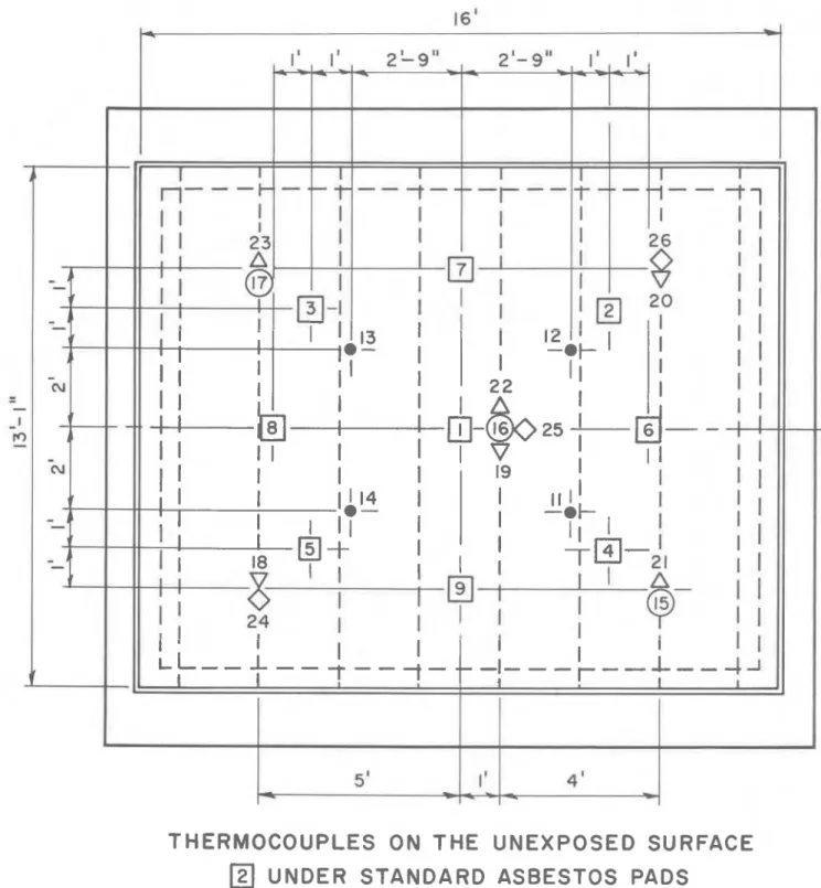
The unexposed s u r f a c e temperature was measured by nine thermocouples (Nos. 1 t o 9 ) covered with standard a s b e s t o s pads, 6 i n . square and 0.4 i n . t h i c k , symmetrically disposed a s shown i n Fig. 4. I n a d d i t i o n , f o u r thermocouples were cemented t o t h e unexposed s u r f a c e i n a way shown i n Pig. 5.
The l o c a t i o n of t h e s e thermocouples (Nos. 11 t o 1 4 ) i s a l s o shown i n Fig. 4.
I n o r d e r t o study t h e flow of h e a t through t h e specimen, twelve a d d i t i o n a l themnocouples were i n s t a l l e d w i t h i n t h e s t r u c t u r e . These thermocouples (Nos. 15 t o 26) were a l s o symmetrically disposed and a r e shown i n t h e general thermocouple l a y o u t drawing ( Pig. 4 )
.
The s u r f a c e of t h e specimen was s u b j e c t e d t o a v e r t i c a l load of 125 lb/sq f t , a p p l i e d through a hydraulic loading device c o n s i s t i n g of 30 jacks. The load was t r a n s -
f e r r e d t o t h e specimen a t n i n e t y p o i n t s ( s e e Pig. 11) s o t h a t t h e c o n d i t i o n of uniform load d i s t r i b u t i o n was reasonably well approximated.
A mechanical device was used t o measure t h e v e r t i c a l d e f l e c t i o n a t t h e c e n t r e of t h e specimen.
A d e t a i l e d d e s c r i p t i o n of t h e f i r e t e s t f a c i l i t i e s of t h e National Research Council i s a v a i l a b l e (1).
RESULTS
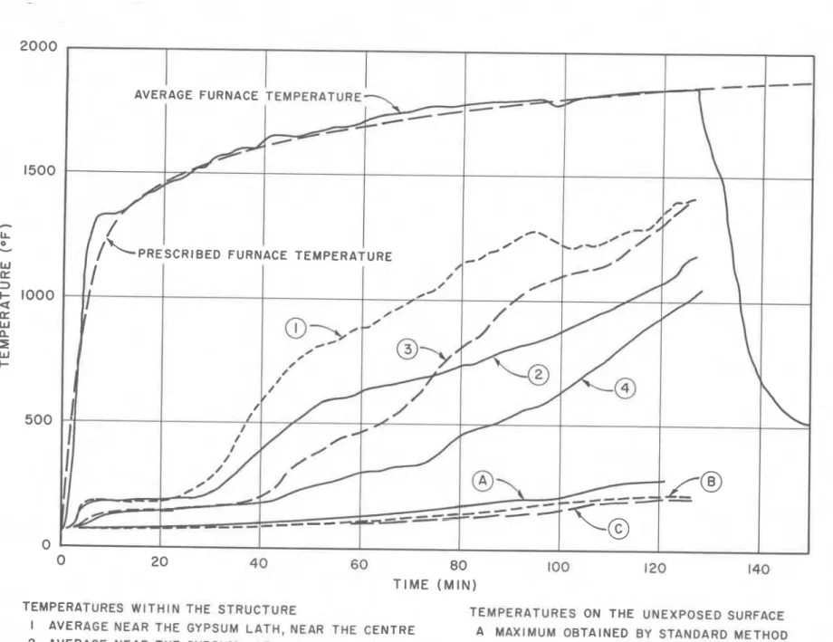
Uniformity of t h e furnace temperature was very good throughout t h e t e s t ; maximum deviation from t h e average was always l e s s than 100°F. A p l o t of t h e average tempera- t u r e a g a i n s t time i s shown i n P i g .
7.
Variation of t h e unexposed surface temperature was roughly i n d i c a t i v e of s t r u c t u r a l d i s i n t e g r a t i o n of the c e i l i n g construction. Where the d i s i n t e g r a t i o n developed more r a p i d l y , moderately higher temperatures were recorded on the unexposed surface. I n Pig. 7 the v a r i a t i o n of both t h e average and the maximum temperatures of the unexposed surface a r e shown.
Thermocouples'~cemented t o the surface recorded somewhat lower temperatures, the average of which i s a l s o p l o t t e d i n t h e same f i g u r e .
Temperatures obtained from various points i n the i n t e r i o r of the s t r u c t u r e showed a very remarkable spread. This was obviously due t o t h e i r r e g u l a r d i s i n t e g r a t i o n of t h e p l a s t e r l a y e r and t h e gypsum l a t h . Generally speaking, the thermocouples placed n e a r e r t h e centre o r the exposed surface recorded higher temperatures than those f a r t h e r f r o m t h e centre o r t h e exposed surface. C h a r a c t e r i s t i c curves a r e shown i n Pig. 7.
The v a r i a t i o n of t h e c e n t r a l (maximum) d e f l e c t i o n and t h e r a t e of d e f l e c t i o n a r e p l o t t e d i n Pig. 8. Deflection of 0.45 in. a t zero time i s due t o t h e imposed 125 lb/sq ft load before t h e s t a r t of t h e t e s t . After 2 hours of t e s t t h e d e f l e c t i o n a t t h e centre became l a r g e r than t h e a v a i l a b l e
s b h of the jacks, so t h a t two jacks around t h e centre became i n e f f e c t i v e . Thus the slope of the d e f l e c t i o n curve shows a sudden decrease a f t e r 120 minutes t e s t i n g .
The f i r e t e s t was terminated a t 2 hours and 7 minutes. According t o ASTM E119-58 t h e t e s t i s regarded a s successful f o r a 2-hour period.
COMMENT
The process of d i s i n t e g r a t i o n of the fire-exposed c e i l i n g s t r u c t u r e appears t o have been a s follows:
Within
5
minute of the s t a r t of the t e s t the f i n i s h p l a s t e r began t o peel from t h e c e i l i n g i n large patches. I n o t h e r places moisture s t a i n s appeared on t h e surface, A f t e r 12 minutes the base p l a s t e r coat commenced t o crack along t h e "Tri-Seal Loop Channels", Cracks gradually opened t o a $-inch width a s the pieces of gypsum l a t h and adhering base coat began t o sag. After 25 minutes o t h e r cracks running a t r i g h t angles t o the previous ones, mostly a t the j o i n t s of t h e pieces of gypsum l a t h , a l s o appeared. Where the various pieces sagged d i f f e r e n t l y , these l a t t e r cracks grew r a p i d l y , and a t 27 minutes the first gap on the c e i l i n g , about .. 1 inch i n width, becamev i s i b l e . I n quick succession other gaps formed and a t 35 minutes the f i r s t l a r g e r s e c t i o n of the gypsum l a t h , approximately 1 6 by 36 i n . i n s i z e , f e l l off the c e i l i n g together with the adhering base coat. The gap and hole formation on t h e c e i l i n g marked the beginning of a rapid temperature r i s e i n s i d e t h e c e i l i n g - f l o o r assembly, a s may be seen i n Fig. 7, and r e s u l t e d i n an increased r a t e of d e f l e c t i o n (Fig. 8 ) .
From t h i s point on t h e d i s i n t e g r a t i o n o f t h e base coat and gypsum l a t h ,developed rapidly, Many new gaps formed perpendicular t o t h e d i r e c t i o n of the "Tri-Seal Loop Channelsw, but t h e t i e wires prevented separate pieces from f a l l i n g down. It was n o t u n t i l 55 minutes a f t e r t h e s t a r t of t h e t e s t t h a t a second, l a r g e r piece of c e i l i n g gave way. A t 1 hour and 18 minu- t e s another l a r g e piece f e l l down and t h e s t e e l j o i s t s became v i s i b l e .
The d i s i n t e g r a t i o n process of t h e c e i l i n g i s i l l u s - t r a t e d i n P i p - 9 - w h e r p +he + n + c a l AC r e -
----
1 - - - - ,p l o t t e d versus time. This curve i s believed t o be c o r r e c t within
-
+
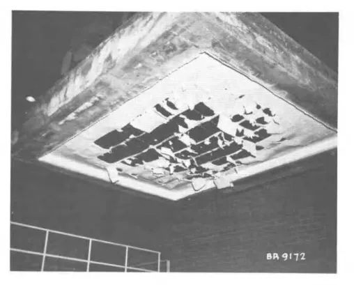
10 per cent.Figure 6 shows t h e s t a t e of t h e c e i l i n g a f t e r the t e s t . The diagram was reconstructed from two photographs
taken immediately a f t e r termination of the t e s t ; one of these i s shown a s Fig, 1 2 . The area of complete d i s i n t e g r a t i o n i s cross-hatched. Within t h i s area s e v e r a l fragments of gypsum l a t h and p l a s t e r were s t i l l hanging on t h e t i e wires, b u t these pieces no longer c o n s t i t u t e d s i g n i f i c a n t s h i e l d i n g f o r t h e
s t e e l j o i s t s .
A s may be seen from Fig. 1 2 , the base coat adhered
very well t o t h e gypsum l a t h throughout t h e t e s t . The two l a y e r s acted a s a s i n g l e u n i t , apparently because of the perforations of the l a t h . It may a l s o be seen t h a t t h e t i e wires played an important p a r t i n the f i r e endurance of the
s t r u c t u r e . They held the pieces of p l a s t e r and gypsum l a t h - I
i n position even a f t e r most of t h e i r s t r e n g t h had been l o s t , and in t h i s way, though i n d i r e c t l y , protected t h e load-bearing s t e e l j o i s t s from t h e r a d i a t i n g heat.
A s mentioned e a r l i e r , several cracks were observed on the surface o f the concrete s l a b before the t e s t . A f t e r
80 minutes a number of o t h e r cracks gradually developed, from some of which steam was issuing, A t such places where the surface was below b o i l i n g point, the steam p a r t l y con- densed i n t h e cracks and slowly f i l l e d them up with moisture, a s i s shown i n Fig. 11.
Robertson and Ryan ( 2 ) developed c r i t e r i a f o r defining t h e load f a i l u r e of f i r e t e s t specimens i n terms of d e f l e c t i o n and r a t e of deflection. It has been proposed t h a t the point a t which both
and
can be regarded a s an i n d i c a t i o n of load f a i l u r e . I n these c o r r e l a t i o n s
D = maximum d e f l e c t i o n , i n . R = r a t e of d e f l e c t i o n , i n . / h r
L = span of t h e p r i n c i p a l s t r u c t u r a l element, i n .
d = d i s t a n c e between t h e upper and lower extreme f i b r e s of the p r i n c i p a l s t r u c t u r a l element, i n . I n t h i s case L = 144 i n . , d = 10.125 i n . , t h e r e - f o r e bhe c r i t i c a l d e f l e c t i o n i s
-
D o r i t-
00 1 4 4 ~ = 2.56 i n . and the c r i t i c a l r a t e o f d e f l e c t i o n-
-
144* R c r i t 150x
10.125 = 13.65 in./hr = 0.228 in./min. These c r i t i c a l values a r e marked with arrows i nFig. 8, It may be seen t h a t by the end o f t h e t e s t t h e maximum d e f l e c t i o n exceeded the c r i t i c a l value by more than t h r e e times, although t h e r a t e of d e f l e c t i o n remained below t h e above defined l i m i t . According t o t h e Robertson-Ryan c r i t e r i a , t h e r e f o r e , t h e f l o o r and c e i l i n g assembly was n o t due t o c o l l a p s e a t t h e time when t h e t e s t was terminated.
1. Shorter, G. W., and T. 2. Harmathy. F i r e Endurance Test F a c i l i t i e s a t t h e National Research Council, N.R.C., Division o f Building Research, DBR F i r e Study No. 1, Ottawa, July 1960. NRC 5732.
2. Robertson, A . P., and J. V. Ryan. Proposed C r i t e r i a f o r Defining Load F a i l u r e o f Beams, Floors and Roof
Constructions During F i r e Test. J. Res. Natl. Bureau Stds.,
-
63C, p.121-124 (1959).- A' -- "
- .
--
I.. . -. I I
THERMOCOUPLES ON THE UNEXPOSED SURFACE UNDER STANDARD ASBESTOS PADS
CEMENTED TO THE SURFACE
THERMOCOUPLES W I T H I N THE STRUCTURE
@
ON TOP OF GYPSUM L A T HV
ON THE BOTTOM CHORD OF STEEL JOISTSA
ON THE TOP CHORD OF STEEL JOISTS0
ON TOP OF METAL FLOOR FORMSF
LEGENDTh
THERMOCOUPLE W I R E SF
FLOORC
CEMENTFIGURE
5
NON
-
STANDARD UNEXPOSED SURFACE
FIGURE 6
THE STATE OF THE C E I L I N G A F T E R FIRE T E S T
(DISINTEGRATED PORTIONS CROSS HATCHED)
T I M E ( M I N I
TEMPERATURES W I T H I N THE STRUCTURE TEMPERATURES ON THE UNEXPOSED SURFACE I AVERAGE NEAR THE GYPSUM L A T H , NEAR THE CENTRE A MAXIMUM OBTAINED B Y STANDARD METHOD 2 AVERAGE NEAR THE GYPSUM LATH, FAR FROM THE CENTRE B AVERAGE OBTAINED B Y STANDARD METHOD 3 AVERAGE N E A R THE CONCRETE SLAB, NEAR THE CENTRE C AVERAGE OBTAINED B Y METHOD SHOWN IN
4 AVERAGE NEAR THE CONCRETE SLAB, FAR FROM CENTRE FIGURE 5
T I M E ( M I N )
FIGURE
8
-
TOTAL AREA OF CEILING SURFACE
=
180 SQ FT3
-
-
-
0 2 0 40 60 80 100 120 140 T I M E ( M I N )FIGURE 9
Figure 10 Plastered surface of the ceiling before the fire test
Figure 11 Development of cracks on the unexposed surface