Design of Miniature Floating Platform for
Marginal Fields
MAby
Sha Miao
B.S., Shanghai Jiao Tong University (2011)
ARCHIVES
SACHUSETTS INSIlTLtE0- TECHNOLOGY
JUN 2 5 2013
L
BRA
RIES
Submitted to the Department of Mechanical Engineering
in partial fulfillment of the requirements for the degree of
Master of Science in Mechanical Engineering
at the
MASSACHUSETTS INSTITUTE OF TECHNOLOGY
June 2013
@
Massachusetts Institute of Technology 2013. All rights reserved.
A u th or ...
... ...
Department of Mechanical Engineering
May 20th, 2013
Certified by ...
-kl
Dick K.P. Yue
Philip J. Solondz Professor of Engineering
Z
X
Thesis Supervisor
Certified by..
...
Yuming Liu
ncipal Res ar h Scientist
is,Sf~risorAccepted by ...
David E.Hardt
Chairman, Department Committee on Graduate Students
Design of Miniature Floating Platform for Marginal Fields
by
Sha Miao
Submitted to the Department of Mechanical Engineering on May 10th, 2013, in partial fulfillment of the
requirements for the degree of Master of Science in Mechanical Engineering
Abstract
This thesis presents the design of a novel type of miniature floating offshore platforms with a heave plate attached at the keel, suitable for developing deep-water marginal fields. This design features a small displacement, easy fabrication, reduced cost and a favourable motion performance in waves. The design process includes the preliminary estimation, hydrodynamic analysis and hull optimization. A self-developed model "Discrete Vortex Ring Model" (DVRM) to efficiently estimate the viscous drag due to the vortex shedding of the oscillatory heave plate is presented in details. This new model DVRM combined with the standard radiation/diffraction code WAMIT is used to analyse the effect of different geometric parameters on the motion behaviour of the platform. Finally, these two models are integrated into a genetic optimization
algorithm to obtain a final optimal design. Thesis Supervisor: Dick K.P. Yue
Title: Philip J. Solondz Professor of Engineering Thesis Supervisor: Yuming Liu
Acknowledgements
I would like to express my deep gratitude to my advisor, Professor Dick K.P. Yue, for
his continuous guidance and patience throughout the first two years of my graduate study. I have benefited greatly working with him not only from his profound knowl-edge and insightful research advice, but also from his research attitude. He helps me to gradually turn into a good researcher who should have critical and deep thinking, creativity, perseverance and systematicness. All of these would help me a lot in the rest of my graduate study and my future career.
In addition, I want to direct my thanks to Dr. Yuming Liu. Whenever I have
questions and problems, he is there to help. Whenever I am frustrated by slow
research progress, he is also there to encourage me and push me forward.
Gratitude also goes to all the members in Vortical Flow Research Laboratory for their tireless answering of my questions. I also would like to thank all my friends for their accompany and assistance.
Finally, I would like to thank my parents Wei MIAO and Qin XUE, for their endless love, understanding and support.
Contents
1 Introduction
1.1 M otivations . . . .
1.2 Wave loads on offshore platform . . . .
1.2.1 Linear wave-induced motion and loads . . . .
1.2.2 Partially nonlinear wave-induced motion and loads
1.2.3 Fully nonlinear wave-induced motion and loads . . .
1.2.4 Viscous damping . . . .
1.3 Objectives and overview . . . .
21 . . . . . 21 . . . . . 22 . . . . . 23 . . . . . 24 . . . . . 25 . . . . . 25 . . . . . 28 2 Preliminary Design Considerations for the Mini-platform
2.1 Functions and configurations of the mini-platform . . . .
2.2 Estimation of the weight distribution of the mini-platform . . . .
2.2.1 Statistics of the weight distribution of the present mini-platforms
2.2.2 Topsides payload of the mini-platform (W,) . . . .
2.2.3 Displacement of the mini-platform (A) . . . .
2.2.4 Hull weight of the mini-platform (WH) . . . .
2.2.5 Ballast of the mini-platform (WB) . . . .
2.2.6 Summary in the weight distribution of the mini-platform . . .
2.3 Estimation of the main dimensions of the mini-platform . . . .
2.3.1 Waterplane radius of the mini-platform (R1) . . . .
2.3.2 Freeboard of the mini-platform (Hf) . . . . 2.3.3 Dimensions of the decks of the mini-platform . . . .
2.3.4 Draft of the mini-platform (H) . . . .
31 31 34 34 34 36 37 38 38 38 39 39 41 41
2.3.5 Dimensions of the heave plate of the mini-platform . .
2.3.6 Summary in the main dimensions of the mini-platform 2.4 Estimation of the inertial parameters of the mini-platform . .
2.4.1 Vertical centre of gravity of the mini-platform (VCG) .
2.4.2 Radius of gyration of the mini-platform (Rg) . . . .
3 Hydrodynamic Models and Numerical Methods
3.1 Equation of motion of a floating body in regular waves . . . .
3.2 Potential flow model for the linear wave-body problem . . . .
3.2.1 Hydrostatic force of a freely floating body . . . . 3.2.2 Radiation problem of an oscillatory body in calm water 3.2.3 Diffraction problem of a fixed body in regular waves .
3.2.4 Panel method for the radiation/diffraction problem .
3.3 Vortex damping model for the viscous drag on the heave plate
3.3.1 Viscous drag of a 2D oscillatory thin plate . . . .
3.3.2 Viscous drag of a circular oscillatory thin plate . . . .
3.4 Solution to the motion equation in regular waves . . . .
3.4.1 Procedure of solving the motion equation . . . .
3.4.2 Derivation of the RAO . . . .
3.5 Motion Response in Ocean Environments . . . .
3.5.1 Description of ocean waves . . . .
3.5.2 Motions of general bodies in irregular waves . . . .
42 42 43 43 44 45 45 47 48 49 50 51 54 55 70 76 76 78 83 83 85
4 Conceptual Design and Analysis for the Mini-platform 87
4.1 Hull shape evolution of the mini-platform . . . . 87
4.1.1 Reduce the stiffness . . . . 89
4.1.2 Increase the added mass . . . . 89
4.1.3 Reduce the wave exciting force . . . . 90
4.1.4 Increase the viscous damping . . . . 92
4.2 An example of the mini-platforms compared with the spar in heave . 93 4.2.1 Comparison in the RAO's . . . . 94
4.2.2 4.3 Effect
4.3.1
4.3.2
4.3.3
Comparison in the response in various sea-states . . . . of the geometric parameters of the mini-platform on heave . . Effect of the draft on heave . . . .
Effect of the axial distribution of the displacement on heave Effect of the radial distribution of the displacement on heave
5 Hull Optimization for the Mini-platform
5.1 Optimization parameters for automatic generation of the hull shape
5.2 Constraints for the mini-platform designs . . . .
5.3 Objective functions for the hull shape optimization . . . .
5.4 Optimization algorithm . . . .
5.4.1 Two concepts: Pareto frontier and -dominance . . . .
5.4.2 Optimization flow based on e - MOGA . . . .
5.5 Final hull shape for the mini-platform . . . .
6 Summary and Recommendations
6.1 Sum m ary . . . . 6.2 Recommendations . . . . 95 97 98 100 104 113 114 117 117 118 118 121 124 129 129 131
List of Figures
2-1 General configuration and definition of the coordinate system for our
miniature floating platform . . . . 32
2-2 Upper and lower bounds of the topside facility weight for typical floaters
as a function of oil production rate, Gulf of Mexico (from Chakrabarti 2005; Vol.1, Ch.7, Sec.7.3) . . . . 35
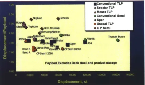
2-3 Displacement/payload ratio as a function of the displacement for
dif-ferent types of floating platforms (from Wybro 2006) . . . . 37
2-4 Statistics of the diameters of the existing spars (Barton, n.d.) . . . . 40
3-1 Definition of the coordinate systems and sketch of body motions in six
degrees of freedom, where (1 ~ (6 represent the displacement in the
corresponding modes (from Newman 1977) . . . . 46
3-2 Sketch of the domain for the boundary value problem and the definition
of the coordinate system, where SF is the free surface, SB is the wetted body surface, S, is the surrounding surface at infinity and SE is an infinitely small surface surrounding a singular point. n' is the normal
vector pointing out of the fluid. . . . . 52
3-3 A two dimensional infinitely thin plate with a length D oscillates in an
unbounded and inviscid fluid. . . . . 55
3-4 A sketch of the distribution of the singularities on the plate and the
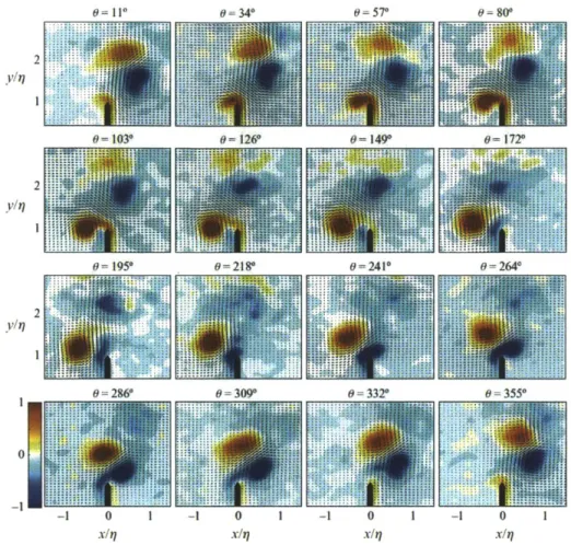
3-5 Sequence of phase-averaged spanwise vorticity and velocity vectors
showing vortex pair formation for KC = 1.07. The phase of the
os-cillation, 6, is given in degrees at the top of each frame. The contour represents the strength of the vorticity. Note the ejection of a single vortex pair in the positive x/r direction, which is a repeatable feature
for each cycle (from Canals & Pawlak 2011). . . . . 64
3-6 The sketch of the "single vortex" approximation. The whole vortex structure is represented by a single point vortex connected to the
sep-aration point by a cut. Xr denotes the location of the point vortex. . 65
3-7 Non-dimensional vortex decay time scale t
d as a function of Rep, which is defined in terms of the vortex circulation. Error bars denote one standard deviation, and the grey shade of each symbol represents the
value of KC for that experiment (from Canals & Pawlak, 2011) . . . 67
3-8 Comparison of the time variation of the total circulation shed at one
edge of the plate 1(t), the vortex shedding rate dF(t)/dt and the total force coefficient C(t) for KC = 3.8. The blue solid line is the result
of VSM, the green solid line is from DVM and the red dash line is the
experimental result adopted from Keulegan & Carpenter (1958) . . . 68
3-9 The wake induced by the sinusoidal oscillation of a flat plate in an
otherwise stationary fluid with KC = 3.8 and V(t) = Vo sin(27rt/T).
The positions of the plate and the free vortex sheets at times t = 0.5KC, 1.25KC, 1.5KC, 2KC, 2.25KC, and 2.5KC are shown. The
first row is the result adopted from Jones (2003). The second row is the result from our VSM. Our VSM uses a slightly different Kutta
condition from the vortex sheet method used in Jones (2003). .... 69
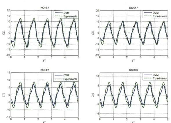
3-10 Comparisons of the time variation of the total force coefficient C(t)
between DVM and experimental data for KC = 1.7, 2.7, 4.7 and 6.6.
3-11 Difference in the average of peak values of the total force coefficient
between DVM prediction and the experimental data for different KC's.
The experimental data is retrieved from Keulegan & Carpenter (1958) 71
3-12 Time variation of the force coefficient due to vortex shedding CFV of
an infinitely thin circular disk oscillating in an unbounded, inviscid,
and otherwise undisturbed fluid based on DVRM, for KC = 0.5, 1, 2,
3 and 5... ... 75
3-13 Time variation of the force coefficient due to vortex shedding CFV of
an infinitely thin circular disk oscillating in an unbounded, inviscid, and otherwise undisturbed fluid based on VRSM, for KC = 0.5, 1, 2,
3 and 5... ... 76
3-14 Time variation of the force coefficient due to vortex shedding CFV of
an infinitely thin circular disk oscillating in an unbounded, inviscid, and otherwise undisturbed fluid for KC = 0.5, 1, 2, 3 and 5 (from De
Bernardinis et al. 1981) . . . .. 77
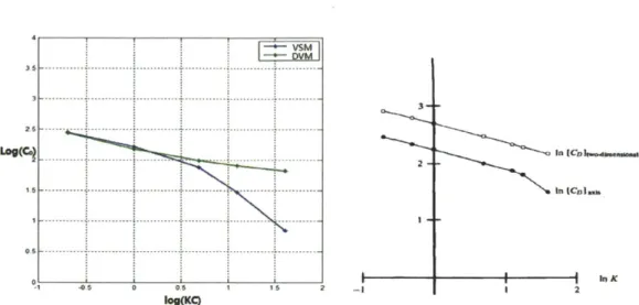
3-15 Comparisons in Drag Coefficients CD as a function of KC number in log scale. The left figure is the result from the codes used in this thesis. The blue line is from VRSM, while the green line is from DVRM. The right figure is the result adopted from De Bernardinis, et al. (1981) . 78
3-16 The flow chart of solving the dynamic motion equation of a
float-ing body in regular waves in combination of the potential flow theory
(WAMIT) and the vortex damping model (DVRM) . . . . 79
4-1 Variation of the heave added mass coefficient as a function of the
di-mensionless oscillation frequency and R2/Ra, for a floating body com-posed of two cylinders with radius R1 and R2 respectively. The
dis-placement and the draft of the body are fixed. Ra, is the radius of a circular cylinder with the same displacement and draft. The
4-2 Variation of the heave added mass coefficient as a function of (R2/Rvg)3
for a floating body composed of two cylinders with radius R1 and R2
re-spectively. The displacement and the draft of the body are fixed. Rvg is the radius of a circular cylinder with the same displacement and draft. The red curve is the linear fitting line based on the scattered
points obtained from WAMIT. . . . . 91
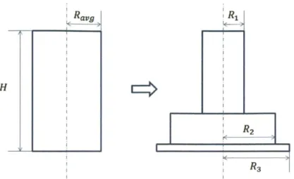
4-3 Sketch of the result of phase I of the hull evolution from a circular cylinder. We shrink the water-plane area, enlarge the keel radius and attach a heave plate at the keel to achieve soft stiffness and large added
mass in heave motion. . . . . 92
4-4 The heave exciting force coefficients for different H1/H from WAMIT. The black curve is the result for a circular cylinder with H = 30 m and
Ra,9 = 11.3 m. The zero force coefficients at low frequencies for the
designs with a shoulder justify the cancellation effect of the exciting
force due to this shoulder. . . . . 93
4-5 Sketch of the result of phase II of the hull evolution from a circu-lar cylinder, to two cylinders with a high even shoulder, and to two cylinders connected by an oblique shoulder. Such a design utilizes the cancelling effect of the heave exciting force, and avoids an abrupt
fluctuation in the cross section. . . . . 94
4-6 Variation of the heave exciting force coefficient for a floating body of two cylinders connected by a shoulder with different inclination a's. The draft of the body H and the length of the lower cylinder H3
/H
are fixed. The calculation results are from WAMIT. . . . . 95
4-7 Summary of all the phases of the hull evolution from a circular cylinder
to the final configuration of the mini-platform . . . . 96
4-8 Sketch of the miniature platform and the spar with the same
4-9 Comparison of the heave RAO of our mini-platform B and the spar
A. The blue curve is the RAO without viscous damping for A. The
green curve is the RAO without viscous damping for B. Both of these two curves are obtained from WAMIT. The red curve is the modified RAO with viscous damping defined in equation (3.107) based on the combination of WAMIT and DVRM. The red curve has a much smaller
peak value compared with the other two curves. . . . . 98
4-10 Modified Pierson-Moskowitz spectrum used for design. The blue curve
is for the operation condition with H, = 4.0 m and T, = 10.0 s.
The green curve is for the survival condition with H, = 12.0 m and
T, = 14.0 s . . . .. . . .. 99
4-11 Variation of heave motion amplitude (s/Hs for the mini-platform as a function of the total draft H/V1/3, where V = 13,000 m3
, H1/H 2 =
H2/H3 = 1, R2
/R
1 = 1.5 and R3/R 2 = 1.3.The results are fromequation (3.122) based on WAMIT and DVRM. . . . . 100
4-12 Variation of the stiffness, added mass coefficients and resonant frequen-cies for the mini-platform as a function of the total draft H/Vi/3, where V = 13, 000 m3
, H1/H 2 = H2/H 3 = 1, R2
/R
1 = 1.5 and R3/R 2 = 1.3.The results are from WAMIT. . . . . 101
4-13 Variation of the wave exciting force coefficient for the mini-platform as a function of the total draft H/V 1/3, where V = 13,000 M3
, H1/H 2 =
H2/H3 = 1, R2/R 1 = 1.5 and R3/R 2 = 1.3.The results are from WAMIT. 102
4-14 Contours of the dimensionless heave motion amplitude (8
/H,
for themini-platform as a function of H1
/H
and H3/H,
while V = 13000 m3,H/V = 1.5, R2/Ri = 1.5 and R3/R 2 = 1.5. The results are from
equation (3.122) based on WAMIT and DVRM. . . . . 103
4-15 Contours of the heave added mass coefficients as a function of H1
/H
and H3/H, while V = 13000 in
3
, H// = 1.5, R2/R1 = 1.5 and R3/R 2 = 1.5. The data is obtained from WAMIT. . . . . 104
4-16 Contours of the dimensionless stiffness as a function of H1/H and
H3
/H,
where V = 13000 M3, H//V = 1.5, R2/R1 = 1.5 and R3/R 21.5. The results are from WAMIT. . . . 105 4-17 Contours of the wave exciting force coefficients as a function of H1
/H
and H3/H, while V = 13000 mI3, H/V = 1.5, R2/R1 = 1.5 and
R3/R2 = 1.5. The results are from WAMIT. . . . . 106
4-18 Contours of the dimensionless heave motion amplitude (8
/H,
for themini-platform as a function of R2
/R
1 and R3/R 2, while V = 13000 MI3,H/V = 1.5, Hi/H = 0.55 and H3
/H
= 0.3. The results are from equation (3.122) based on WAMIT and DVRM. . . . 1074-19 Contours of the added mass coefficient for the mini-platform as a function of R2/R1 and R3/R 2, while V = 13000 M3, H//IY 1.5,
H1/H = 0.55 and H3/H = 0.3. The results are from WAMIT. . ... 108 4-20 Contours of the viscous damping coefficients for the mini-platform as
a function of R2/R1 and R3/R2, while V = 13000 m3, H/V = 1.5,
H1/H = 0.55 and H3/H = 0.3. The results are from DVRM. . . . . . 109 4-21 Contours of the dimensionless softness for the mini-platform as a
func-tion of R2/R1 and R3/R 2, while V = 13000 M3, H// = 1.5, HI/H = 0.55 and H3/H = 0.3. The results are from WAMIT. . . . . 110 4-22 Contours of the dimensionless resonance frequencies in heave for the
mini-platform as a function of R2
/R1
and R3/R 2, while V = 13000 in3,H/N _ = 1.5, H1
/H
= 0.55 and H3/H
= 0.3. The results are from W A M IT . . . 1114-23 Contours of the wave exciting force coefficients for the mini-platform as a function of R2/R1 and R3/R 2, while V = 13000 M3, H/fV = 1.5,
H1/H = 0.55 and H3/H = 0.3. The results are from WAMIT. . . . . 112
5-1 Framework of the parametric optimization of hull shape . . . . 114
5-3 Illustration of the Pareto frontier. The black circles represent the
fea-sible designs, the green circles are designs of Pareto frontiers, and the
red crosses denote the infeasible designs violating the constraints. . . 119
5-4 Illustration of the concept of usual-dominance and c-dominance (from
Deb et al., 2003) . . . . 120
5-5 Illustration of the single point cross over for two parents to generate
two children . . . . 122
5-6 Illustration of the procedure of c-MOEA (from Deb et al., 2003) . . . 124
5-7 Final Pareto frontier of the Multi-objective optimization for the hull
shape of the mini-platform when the population number reaches 350. The objective functions are evaluated based on the combination of
WAMIT and DVRM. . . . . 125
5-8 Hull shape of the selected designs from the final Pareto frontier of a
List of Tables
2.1 Statistics of the weight distribution of the payloads, hull weight and displacement of the present mini-platforms, where Wp is the topsides payload, WH is the self-weight of the hull, and A is the displacement
(from Hudson & Vasseur 1996; Wilhoit 2010; Kibbee et al. 1999;
Kibbee & Snell 2002; Koon et al. 2002; Ronalds 2002; Cermelli et al.
2004) . . . . 34
2.2 Statistics of the draft H of the present mini-platforms (from Wilhoit
2010; Kibbee et al. 1999; Kibbee & Snell 2002; Koon et al. 2002;
Cerm elli et al. 2004) . . . . 41
2.3 An example of the estimation of the VCG of the platform based on the
weight distribution of different components at the initial stage, where
the coordinate . . . . 43
4.1 Dimensions of the spar A and newly designed mini-platform B. . . . . 94
4.2 The characteristic parameters of the design condition of the sea-states.
H, is the significant wave height. T, is the peak period of the wave
spectrum. The data is retrieved from ITTC. . . . . 95
4.3 Comparison of the significant heave motion height (, in various
sea-states for spar A and mini-platform B, where GM denotes the hydro-static metacentric height, and T is the natural periods in heave. The
result is obtained from the combination of WAMIT and DVRM. . . . 96
5.1 Upper and lower limits of the five free optimization variables to describe
5.2 Dimensions and optimization objectives of the selected designs of the
Chapter 1
Introduction
1.1
Motivations
Humans' demand for hydrocarbons is expected to increase by 5% per year for the following decades, but very large oil and gas fields are fewer and fewer. Therefore, oil and gas companies are transitioning to look for means of developing their proven smaller reserves, which are so-called "marginal fields". A lot of such reserves have already been discovered in the deep water of Gulf of Mexico recently. However, the expenses of a stand-alone deep-water field development, including a platform and pipeline infrastructure, are usually beyond the value of the oil or gas it contains. Nowadays, providing surface support to deep water developments is mainly achieved
by three types of platforms, all of which are costly.
Semi-submersible platforms are moored floating structures composed by multiple columns connected by pontoons. This kind of platforms achieves its stability by large displacement, normally exceeding 20,000 tons. Therefore, such platforms can support a large payload, but at the same time their cost is high. In addition, their large displacement requires very large mooring system, which increases significantly in size and cost with water depth.
Spars are a hollow vertical cylindrical structure moored to the sea bed. Such plat-forms usually have a very deep draft to minimize heave motion, but this also increases the system cost. In addition, another inherent problem of such concept is that the
cylinder suffers greatly from Vortex Induced Motions (VIM) in the current. These induced oscillations would reduce the fatigue life of the mooring system, resulting in operational concerns. One of the most common mitigation devices is strake. But strakes increase the wetted surface of the platform and the strength requirements of the mooring system. The spar installation and fabrication costs are also high.
Finally, tension leg platforms (TLP) have also been widely used to support deep water facilities in depth extending to almost 5,000 ft. TLPs are connected to the sea-bed by a set of vertical steel tendons, like an inverted pendulum. These tensioned tendons limit the heave and pitch motion very well. Due to the motivation from the marginal fields, a lot of mini-TLPs were invented, such as Seastar mini-TLP and Modec mini-TLP. However, TLP cannot be extended to the ultra deep water greater than 5,000 ft and the installation of these tendons is very expensive. In addition, the tendons are subject to Vortex-Induced Vibrations (VIV), which makes their design challenging.
The existing floaters are all very large and costly. Marginal fields cannot support these costs. This motivates the industry to seek for a clever design of a novel miniature
floating platform with loose mooring systems, of which the displacement is around 104
ton. In addition, such mini-platforms should also have a good motion performance in waves. However, it is quite challenging to achieve both goals at the same time. This thesis would focus on how to find such an economic but also safe design.
1.2
Wave loads on offshore platform
It is essential to predict the wave-induced loads and motion in both design and op-eration of the offshore platforms. Motions of floating platforms usually involve six degrees of freedom. The rigid-body translatory motions are surge, sway, and heave. The angular motions are referred as roll, pitch and yaw.
To date, the majority of research has assumed that the water can be considered as incompressible and inviscid, and that the flow around the body remains irrotational. Under this assumption, the Laplace equation is valid everywhere in the fluid domain
and the hydrodynamic forces acting on the body can be considered as the solution to the boundary value problem. However, this is not implying that viscous effects are not important. On the contrary, for certain phenomena they are dominant. However, the inviscid fluid problem is an order of magnitude easier to solve and therefore has been the basis for much of the research in the area. For many types of problems and geometries the inviscid assumption gives quite an acceptable accuracy (Beck 1994).
1.2.1
Linear wave-induced motion and loads
Under operational conditions when the amplitudes of incident waves and body mo-tions are relatively small, linear theory in the frequency domain generally gives good predictions for wave body interactions. Based on the linear wave theory, a sea state is usually described by a wave spectrum and a floating body's response to this ran-dom sea can be approximated by superposing the body's response to each regular incident wave component in the spectrum (St. Denis & Pierson 1953). The solution of regular incident wave interactions with floating bodies can be obtained by solving the boundary value problem which can be further split into seven sub-problems: a radiation problem associated with forced harmonic oscillations in six modes of rigid body motion, and a diffraction problem when the body is fixed in incident regular waves. In each of these sub-problems, a velocity potential is found as the solution of the Laplace equation subject to a body boundary condition applied on the mean wet surface, a sea-bottom condition, the classical linearized free surface condition and a radiation condition at far field. For a general body shape, numerical schemes are usually used, including finite difference, finite element, finite volume, and bound-ary element methods. Among all these numerical schemes, the potential-flow based boundary element methods (panel methods) using a Green function technique have gained great popularity due to their efficiency, accuracy, and flexibility (King 1987; Newman & Sclavounos 1988; Newman 1992). From the linear theory, wave-induced body motion reserves wave frequency and has the motion amplitude linearly propor-tional to the incident wave amplitude.
complementary via Fourier transforms. However, the conventional frequency-domain approach is computationally much faster than the time-domain approach. In addi-tion, the linear method in frequency domain can capture most of the leading order effects in a mild sea condition. Therefore, it is widely used to explore the design space at the preliminary design phase, to understand the system responses and to obtain fundamental insights into the optimization of the systems' design. Since this thesis focuses on the concept design and preliminary optimization of a novel floating platform, the standard linear Radiation/Diffraction theory in the frequency domain is used.
1.2.2 Partially nonlinear wave-induced motion and loads
The biggest limitation of a frequency domain analysis based on the linear wave and linear dynamics theory is that the amplitudes of ambient wave and body motions have to be small compared to the ambient wavelength. However, extreme wave envi-ronments under nonlinear effects could also be of importance.
The most common way to solve the nonlinear wave body interaction problem is to use perturbation analysis with the ratio of wave amplitude and wavelength as a small parameter. If we extend the linear theory to the second order, i.e., the free surface and body boundary conditions are satisfied up to the second order in the wave steepness, we could obtain nonlinear wave forces of sum- and difference-frequencies. If these frequencies are close to the natural frequencies of the system, resonance would also occur (Faltinsen 1990).
There are other studies taking partial nonlinearity effects into account in the wave-body interactions. One is the body-exact numerical method which is usually for practical problems involving large-amplitude body motions but relatively small incident and diffraction waves. The body boundary condition is implemented on the exact instantaneous wet body surface while the free surface condition is linearized at the undisturbed water surface (Lin & Yue 1991; Faltinsen & Chezhian 2005). The other is called "weak-scatter theory". This theory linearizes the free surface boundary condition on the incident wave profile, and still satisfies the exact body
boundary condition. This is one step further than the body-exact theory, but still has limitations on the nonlinearity of disturbance flow (Pawlowski 1992; Huang 1997). Since the body boundary condition is satisfied on the instantaneous wet surface, time domain analysis is the convenient alternative, but much more time consuming in computation.
1.2.3
Fully nonlinear wave-induced motion and loads
For problems like slamming, green water on deck and wave over-topping, fully non-linear numerical simulation is required. However, because of the computational cost and complexity in modelling the muti-scale nonlinearities, such three-dimensional fully nonlinear results for general bodies are still limited. One of the most popular methods is the mixed-Eulerian-Lagrangian (MEL) approach combined with a bound-ary element method (BEM). At each time step, the BEM is first used to solve the BVP, and the MEL is then used to update the nonlinear free surface (Dommermuth
& Yue 1987; Liu, Xue & Yue 2001). Finite difference methods or finite volume
meth-ods, which are much more computationally expensive than the BEMs, are at present not practical in the study of fully nonlinear wave-body interaction for the design of offshore structures.
1.2.4
Viscous damping
Viscous damping is of importance in the design of offshore platforms because it can be utilized for suppressing the motion of the platform. However, the state of the art in calculating the viscous loads on offshore structures is not satisfactory. Tradition-ally, Morison's equation (Morison et al. 1950) has been widely used to calculate wave and current loads on cylindrical structures. The inertia and drag coefficients have to be empirically or experimentally determined. In addition, Morisons equation can-not predict the oscillatory forces due to vortex shedding. This motivates numerous researches in developing more rational methods for estimating the viscous damping effects.
The simplest model to use is a single-vortex model. This is an inviscid method that models the flows with thin vortex sheets separated from sharp corners at high Reynolds numbers and low Keulegan Carpenter numbers (KC). This model represents the vortex sheet by a single vortex and a cut joining this single vortex and the adjacent separation point. Brown & Michael (1955) first applied the condition of total zero force on the sum of the single vortex and the cut to determine the location of the vortex. Kutta condition is satisfied at the separation point to determine the strength of the vortex. Faltinsen & Sortland (1987) used a similar idea to study drag coefficients for an arbitrary two-dimensional bodies with sharp corners and obtained good results compared to the experiments. Stiassnie et al. (1984) applied the single vortex method on oscillating problems to estimate the energy dissipation due to the vortex shedding at the lower sharp edge of a vertical plate in waves. They assumed only one pair of vortices shed per period and neglected the influence of previously shed vortices, focusing on one half cycle only. The result has the same trend compared to the experiment, but the error is not trivial. In addition, his method is limited to 2D simple geometry with known analytical solution for the same problem with no vortex. Graham (1977) also attempted to apply this simple method on more general oscillatory flow, but the calculation becomes invalid if the vortex shedding rate changes the sign. Long time calculation will lead to a divergent result.
Graham (1980) later carried out a semi-analytical analysis for KC-+ 0. He as-sumed that the vortex flow for a small KC number depends on the local flow around the sharp edge only. He found out a qualitative relation between the drag coefficient and the KC number. However, the analysis is for the 2D problems and only gives qualitative results.
Usually Reynold's number associated in hydrodynamic problems for marine struc-tures is very large. Therefore, when vortex shedding occurs, the boundary layer is very thin. This motivates researchers to use vortex sheet method to model the sepa-ration phenomenon. A vortex sheet is actually a line of distribution of vorticity. For
2D problems, Jones (2003) proposed a general computational method for the flow
on both sheets and the plate, and did not use conformal mapping method which is widely used for solving 2D problems. Hence such method can be generalized to tackle
3D problems. However, his method cannot do the simulation for long time. As for 3D
axisymmetric problems, not too much work has been done until now. De Bernardinis et al. (1981) and Nitsche & Krasny (1994) applied the vortex ring method to some axisymmetric problems. For 3D problem, vortex sheet method is commonly used in BEM to distribute the dipoles or vorticity on body and the vortex sheet. Kutta con-dition is applied on each time step to determine the strength of the newly shed sheet.
Such scheme can predict the drag coefficients accurately but very time-consuming. In addition to the numerical methods, another popular approach is to measure the drag coefficients by experiments and plug them into the Morison's equation. As for experiments, Keulegan & Carpenter (1958) measured the force of a fixed 2D thin plate in oscillating flow and found that the drag coefficient is a function of KC number. Very recently, Canals and Pawlak (2011) also studied this 2D problem experimentally, but focusing more on the vortex dynamics. He et al. (2008) studied the hydrodynamics of a thin 3D circular plate oscillating by experiments, and found that the viscous damping coefficient depends on both KC number and the diameter-thickness ratio of the plate. However, we should note that it is impossible to do experiments to obtain the viscous damping force for every case of the design at the initial stage.
As we can see, the separated flow around the marine structure is such a compli-cated phenomenon that a general feature of the existing methods is that a simple model will have deficiencies, therefore leading to more complicated numerical mod-els. The result of this trend is that one ends up wanting to solve numerically the Navier-Stokes equations for turbulent flows. However, the solution of NS equations with turbulence is still unrealistic (Rodi 1985). It is not a wise choice to spend much time and computation power only to obtain a drag coefficient while all the other major hydrodynamic coefficients can be obtained by standard radiation/diffraction method within a minute. So rather than following the trend with a more and more complicated model, one may be attempted to go the opposite way and try to find a simple model which can capture the important features of separated flow.
In this thesis, we propose a simple model based on the single vortex idea to estimate the drag coefficient due to the vortex shedding very quickly, both for 2D and 3D axisymmetric cases. The results agree with the experiments satisfactorily. We then combine this simple model with the standard Radiation/Diffraction method to obtain an optimum design of a miniature offshore platform for marginal fields.
1.3
Objectives and overview
The research objectives of this thesis would include the following three parts. The first thing is to come up with a new design of a mono-column mini-platform from hydrodynamic analysis. Since we hope to utilize the viscous damping effects to im-prove the motion behaviour of the platform in waves, a quick model accounting for this damping effects would be developed. Finally, we would combine the hydrody-namic analysis and viscous damping model to carry out the optimization to obtain the optimum design.
This thesis is organized into six chapters.
Chapter 1 provides an introduction of the motivation and research goals of the present work. A brief literature review of the calculation of the hydrodynamic loads is also given.
Chapter 2 would concentrates on some preliminary considerations on design, in-cluding the estimation of the main dimensions and weight distribution.
In Chapter 3, we would present the hydrodynamic models and methods used for design in details: the linear Radiation/Diffraction method (WAMIT), and the newly developed vortex damping model. For the viscous damping problem, we would first discuss the widely-used vortex sheet method in 2D problems, and then focus on the self-developed new model, called "Discrete Vortex Method" (DVM). Then this new model will be extended to 3D axisymmetric problems, called "Discrete Vortex Ring Method" (DVRM), and compared with the widely-used vortex ring sheet method. Finally, we combine this new model DVRM with WAMIT to derive the solution to the hydrodynamic equation of motion.
Chapter 4 applies the models and methods to the design of hull shape of our mini-platform. We first discuss the evolution of the hull shape of our platform from a spar with the same displacement and draft. Next, we presents an initial design of our platform compared with the spar in the heave motion quantitatively to show the advantage of our design, using the combination of WAMIT and DVRM. Finally, how different geometric parameters influence the motion performance is discussed to provide some guides for the following optimization.
Next in Chapter 5, we use a multi-objective genetic optimization algorithm to
find the optimal hull shape for our mini-platform. The combination of WAMIT
and DVRM is integrated into the optimization algorithm to achieve an efficient and automatic calculation.
Finally Chapter 6 summarizes the whole thesis and provides some recommendation for the future work.
Chapter 2
Preliminary Design Considerations
for the Mini-platform
This chapter will discuss several important considerations in the initial design phase. Our objective is to design a mono-column floating platform for deep water with
dis-placement around 104 ton and satisfactory motion performance. For floating
struc-tures, in addition to the hydrodynamic response in waves, the weight control and stability are also key design challengers. Therefore, before we perform any hydrody-namic analysis, the first job is to determine the size and weight distribution of the platform to guarantee that such a design satisfies the hydrostatic stability criteria
and is compatible with its function.
2.1
Functions and configurations of the mini-platform
In the design of a platform, a clear knowledge of the functions should be in hand. This will strongly influence the configuration of the platform. Production, storage, drilling and workover are the four major functions currently performed by floating platforms (Chakrabarti 2005; Vol.1, Ch.7, Sec.7.2.2). Since we target at designing a floating platform with a displacement around 10,000 ton, the carrying capacity of our platform is limited. Therefore, the function of our platform is defined for production only, similar to mini-TLPs (Ronalds 2002). The oil production for the
present miniature platforms usually ranges from 30 - 40k barrels per day (bpd)
(Wilhoit 2010; Ronalds 2002). Here we initially set the oil production rate for our mini-platform to be 30k bpd. X2 Deck -X1 A i" A A-A Ri H
44
:
I
Heave PlateFigure 2-1: General configuration and definition miniature floating platform
of the coordinate system for our
The general configuration of our platform is shown in Figure 2-1. We define a
coordinate system with the origin at the mean waterline and the vertical coordinate X2
coinciding with the axis of symmetry. As can be seen, the mini-platform is composed of three parts: deck structures above the waterline, a hull with a moonpool inside, and a heave plate attached at the bottom of the hull. The topsides deck is a multi-level structure supported by the submersible part. It is mainly used for supporting the weights due to the facilities for oil production. The submersible part is called "hull". For such kind of single-column floating platforms, there is normally an opening with several well slots inside the hull, called "moonpool" (Chakrabarti 2005; Vol.1, Ch.7, Sec.7.7). The function of this moonpool is to allow technicians to lower pipes and instruments into the sea. Finally, the thin plate attached at the keel is called "heave plate", which is a commonly used device to mitigate the motion amplitude of the
d R3
platform.
The main dimensions of the platform is also provided in Figure 2-1.
9 Hf is called "freeboard", which is the distance between the waterline and the
lowest deck level;
o H is the total draft of the submersible part of the platform;
o R1 is the radius of the water-plane area; o R3 is the radius of the heave plate;
o Ro is the dimension of the extension of the heave plate relative to the hull. The weights of the different components of the platform are defined as follows:
" Wp is the topsides payload, representing the sum of the carrying capacity of a platform and the self-weight of its deck structures;
" WH is the weight of the hull;
" A is the displacement, a representative of the scale of a platform. It refers to the total mass of the sea water displaced by the submersible hull.
Another two important parameters reflecting the inertia of the platform are also in need at the initial stage.
" VCG stands for the vertical coordinate of the centre of gravity;
" R. is the radius of gyration for pitch (or roll), which is usually used to describe the mass distribution around the axis of symmetry;
In the following sections, we will discuss how to distribute weight among different configurational components, how to estimate the main dimensions, and how to obtain the parameters of inertia.
Name Type WP/t WH/t A/t Minifloat IV semi 4,000 - 12,698 Morpeth mini-TLP 3,175 2,540 10,605 Allegheny mini-TLP 3, 719 2,359 10,605 Typhoon mini-TLP 3,810 2,817 12,157 Prince mini-TLP 5,533 3,175 13,097 Matterhorn mini-TLP 12,208 5,352 14,881
Marco Polo mini-TLP 12, 700 5, 216 24,947
Table 2.1: Statistics of the weight distribution of the payloads, hull weight and dis-placement of the present mini-platforms, where Wp is the topsides payload, WH is the self-weight of the hull, and A is the displacement (from Hudson & Vasseur 1996;
Wilhoit 2010; Kibbee et al. 1999; Kibbee & Snell 2002; Koon et al. 2002; Ronalds 2002; Cermelli et al. 2004)
2.2
Estimation of the weight distribution of the
mini-platform
2.2.1
Statistics of the weight distribution of the present
mini-platforms
There are numerous miniature platforms to date and most of them are mini-TLPs. Table 2.2.1shows the statistics of weight distribution for the present miniature
plat-forms (from Hudson & Vasseur 1996; Wilhoit 2010; Kibbee et al. 1999; Kibbee &
Snell 2002; Koon et al. 2002; Ronalds 2002; Cermelli et al. 2004)). These data can provide us a guide for the initial estimation. In the following context in this section,
emphasis is put on the estimation of Wp, WH and A.
2.2.2
Topsides payload of the mini-platform (Wp)
The topsides payload is the total weight above the waterline, which measures the carrying capacity of a platform. It can be further divided into three parts: facilities weight, drilling or workover weight, and the deck structure weight (Chakrabarti 2005;
Facility weight of the mini-platform
Facility weights represent the maximum fixed plus the variable payload weights carried
by the hull, normally excluding drilling. These weights can be estimated according to
the export production of the platform. Figure 2-2 shows the typical range of facility weights for the Gulf of Mexico (GOM) floaters as a function of oil production rate
(Chakrabarti 2005; Vol.1, Ch.7, Sec.7.3).
25000 20000 16000 10000 5000 0 0 20 40 60 80 100 Production, 1000 BPD 120 140 160
Figure 2-2: Upper and lower bounds of the topside facility weight for typical floaters as a function of oil production rate, Gulf of Mexico (from Chakrabarti 2005; Vol.1,
Ch.7, Sec.7.3)
The oil production rate in our case is 30 k bpd, so the facility weight can be estimated to be around 2,500 st, i.e., 2,300 ton.
Drilling or workover weights of the mini-platform
Drilling or workover weights are the self-weights of the drilling or workover rigs. Since our platform is designed for production instead of drilling or completion, we can ignore this weight.
Deck structure weight of the mini-platform
Usually the self-weight of the deck structure is 30 ~ 40% of the weight of facilities and
drilling equipment (Chakrabarti 2005; Vol.1, Ch.7, Sec.7.3). Therefore, this weight
item is at least around 700t.
The sum of the above three items arrives at a total weight of the topsides around
3,000 ton. We can also justify the reasonableness of this value from the statistics in
Table 2.2.1 and the principles of stability for different types of platforms. Table 2.2.1 shows that for the present mini-platforms (mini-TLPs and a semi-submersible) with a displacement less than 13, 000 ton, their payloads normally range from 3, 000 to 4, 000 ton. Since the stability of the TLPs is mainly achieved by tendons, and that of semi-submersibles is by the restoring moment of the multiple columns, i.e., "column-stabilized", both of them allow the centre of gravity above the centre of buoyancy. Contrarily, for single-body floating platforms like Spars, or our mini-platform, the gravity centre must be lower than the buoyancy centre to guarantee enough stability. This implies that TLPs have the highest gravity centre, semi-submersibles come the second, and Spars own the lowest in general. Therefore, TLPs generally have a relatively larger payload-displacement ratio compared to other types of platforms. In other words, with the same displacement, mini-TLPs hold a larger topsides capacity than our platform. Hence 3, 000 ton should be a reasonable estimation for the topsides payload in our case if we assume the displacement is also no more than 13, 000 ton.
2.2.3
Displacement of the mini-platform
(A)
Our design purpose is a miniature platform, so the displacement of the platform should be limited. Referring to the previous statistics in Table 2.2.1, we can see that
most of the mini-platforms have a displacement of 10,000 - 15,000 ton. Similarly,
we should confine our platform within this range.
We can also estimate the displacement according to the displacement/payload ratio and the topsides payload obtained in the previous subsection.
Figure 2-3: Displacement/payload ratio as a function of the displacement for different types of floating platforms (from Wybro 2006)
the smallest displacement/payload ratio, semi-submersibles take the second place, and Spars have the largest ratio. This is consistent with the previous statement inferred from the principles of stability of these three types of platforms. We can also see from Figure 2-3 (Wybro 2006) that for mini-platforms with displacement below 20, 000 ton, mainly mini-TLPs, their displacement/payload ratio are mostly near 5.0. Therefore, it is reasonable to assume the ratio of our platform slightly larger, about 5 - 6. The
payload (excluding deck steel) for our platform is 2,300 ton, so the displacement A should be around 11, 500 ~ 13,800 ton. Here we can set it to be 13, 000 ton.
2.2.4
Hull weight of the mini-platform (WH)
In practice, the approaches of estimating the hull steel weight for a semi-submersible and a TLP in the initial design stage are similar (Chakrabarti 2005; Vol.1, Ch.7, Sec.7.5-7.6). Here we also apply this estimation approach to our mini-platform. At this stage we know little about the structure of the hull, one common way is to use a steel density for the enclosed hull volume. For semi-submersibles, values of between
10 lb/ft in the upper sections to 151b/fta in the pontoons are typical (Chakrabarti
p, = 0.208 t/m 3, and ignore the volume between the topsides and mean water line which is small compared to the submersible part.
WH = p8V = 0.208 X (11500 ~ 13800) = 2392 ~ 2870.4 ton (2.1)
where p, is the average steel density of the hull; V is the displaced volume of the platform.
In addition, from Table 2.2.1, the hull weights for miniature platforms usually lie at 2000 - 3000 ton. Therefore, we can set WH to be 2800 ton in the initial design phase.
2.2.5
Ballast of the mini-platform (WB)
The ballast is needed to adjust the vertical centre of gravity to ensure enough stability.
The weight of the ballast WB should be the difference between the total loads exerted
on the platform and the displacement A.
2.2.6
Summary in the weight distribution of the mini-platform
In summary, the weight distribution would be:
(1) A: 13,000 t
(2) Wp: 2,500 t
(3) WH: 2,800 t
2.3
Estimation of the main dimensions of the
mini-platform
Having obtained the weight distribution of the platform, we pay our attention on the dimensions defined in section 2.1 in this section.
2.3.1
Waterplane radius of the mini-platform (R1)
As mentioned earlier, such kind of mono-column platforms normally have a moonpool in the centre of the hull (see Figure 2-1). For mini platforms, well counts are generally 4 - 6 (Kibbee et al. 1999). Spars can be referred to to estimate the size of the
centerwell. To date, all the centerwells of spars have been square, leading themselves to 4 x 4, 5 x 5, or 6 x 6 well slots. Slot spacing for existing centerwells ranges from
8ft to 14ft. The size increases with water depth because of the higher tensions
required. The recommended spacings for spars would be (Chakrabarti 2005; Vol.1, Ch.7, Sec.7.6):
Up to 3000ft water depth 12ft
3000 - 5000ft 13ft
Greater than 5000ft 14ft or more
For our platform, we assume a moonpool of 2 x 2 square and use 12ft as the slot spacing. Then the dimension of the centerwell is around 2 x 12ft ~ 7.2m. Based on the Figure 2-4 (Barton, n.d.), the diameter of the spar is usually 2 times the dimension of the centerwell. Therefore, R1 should be at least 7 m.
2.3.2
Freeboard of the mini-platform (Hf)
Freeboard Hf is defined as the distance from the mean water line to the lowest deck level (see section 2.1). The estimation of this dimension is determined by the estimation of the "Air Gap (Ha)". Air gap means the distance between the highest wave crest and the deck. For the US GOM conditions, API RP2A (1993, 2000) recommends that this air gap should be a minimum of 5 ft, i.e., Ha = 1.5 m. The highest wave, or the crest level above still water, is specified with the design wave height H,. For deep water, we usually estimate the crest level above mean water line to be H, (Chakrabarti 2005; Vol.1, Ch.7, Sec.7.5). For survival condition (100-year return period), we consider the significant wave height (H,) to be 12.0 m, and the peak wave period (T,) to be 14.0 s. Thus the extreme crest elevation He:
Spar Hull Diameter Comparison
RE
3717 WqW~n0
W7430
noMuW 29.97 no42 go: %32.3m) 56'M.3ti 47x42'
~~52
W 157r M) S 10 UIUA ROOM16V TMENT 36xW 12372 r# S' SV5 60X 6 6X 04 00 DOG12 9M 12f0Gm -MU mo 14g.2815.5r TUM 751' X U 30570160 IrSS X 55Figure 2-4: Statistics of the diameters of the existing spars (Barton, n.d.)
2 2
He -H, = - x 12 = 8 m (2.2)
3 3
However, there can be too much air gap. Excessive air gap raises the centre of gravity and thereby impairs the payload performance. Determination of the effective free-board should take the relative motions of the hull into account. For large, long period waves, such a floating platform will tend to rise and fall synchronously with the waves, possibly as much as 20% of the wave height. To recognize this, in initial design, it can be conservatively assumed that the platform rises 10% of the wave height. Then setting the calm water deck height at 5 ft plus 90% of He should suffice
(Chakrabarti 2005; Vol.1, Ch.7, Sec.7.5). Thus the free-board Hf should be at least:
Hf = Ha + 90%He = 1.5 + 0.9 x 8 = 8.7m (2.3)
Thus, we can finally set the Hf to be 9 m. sonM
0801111M ummONE UMMI
name description draft H/m minifloat IV semi 30 Morpeth mini-TLP 27.7 Allegheny mini-TLP 27.7 Typhoon mini-TLP 27.7 Matterhorn mini-TLP 32 mini-TLP 28.51 WADO mini-TLP 28.5 Prince mini-TLP 34.75
Marco Polo mini-TLP 39.6
Table 2.2: Statistics of the draft H of the present mini-platforms (from Wilhoit 2010;
Kibbee et al. 1999; Kibbee & Snell 2002; Koon et al. 2002; Cermelli et al. 2004)
2.3.3
Dimensions of the decks of the mini-platform
Due to the limit of small water plane area, the deck usually has two or three levels
for mono-column floaters (Chakrabarti 2005; Vol.1, Ch.7, Sec.7.6) . Here we can refer
to the topsides of SeaStar miniTLP which is also a mono-column small production platform. The deck has two levels. The dimensions of the deck is 27.4 m x 27.4 m (Kibbee et al. 1994). Since we hope to lower the gravity as much as possible, we initially choose 6 m to be the distance between the two levels.
2.3.4
Draft of the mini-platform (H)
Our platform is similar to spars in achieving hydrostatic stability by placing the gravity centre below the buoyancy centre. The product of inertia of the water plane usually contributes little. Therefore deeper draft is beneficial for lowering the centre of gravity. In addition, deeper draft tends to decrease the area of waterplane, thereby reducing hydrodynamic motions. However, large draft would result in heavier steel for the lower part of the hull. Hulls with shorter drafts and larger diameters have less surface area and less steel. Referring to Table 2.3.4 (from Wilhoit 2010; Kibbee et al. 1999; Kibbee & Snell 2002; Koon et al. 2002; Cermelli et al. 2004), we can see that most of the drafts of the present miniature platforms are around 30 m. Hence we can initially select the draft H around 30 m.
2.3.5
Dimensions of the heave plate of the mini-platform
As mentioned in section 2.1, heave plates are one of the most common motion-suppression devices in offshore floating platforms. They can increase heave added mass and viscous damping effectively without increasing too much displacement. Larger R3 tends to generate larger added mass, beneficial for the hydrodynamic
mo-tion. For smaller R3, interference of the hull boundary on the vortex formation and
shedding process at the edge of the heave plate suppresses the vortices, resulting in lower damping (Tao & Cai 2004). However, since the draft of our platform is not too deep, larger plate would induce larger wave exciting force. Also, large heave plate would bring inconvenience in transportation and installation of the platform. Therefore, we need to make a trade-off when selecting the dimension of the heave plate.
As for thickness, thinner plates generally have more significant damping effects. This is because small thickness enhances the interaction of the vortices formed during any two successive half cycles (Tao & Thiagarajan 2003; Tao & Cai 2004). Therefore, we should try to minimize the thickness. Let us set it within 0.2 - 0.7 m at this
initial phase.
2.3.6
Summary in the main dimensions of the mini-platform
In summary, the main dimensions of our platform would be:
(1) Waterplane: R1 > 7.0m
(2) Freeboard: Hf - 9m
(3) Deck: 27.4m x 27.4m x 6m