HAL Id: hal-01974517
https://hal-univ-paris.archives-ouvertes.fr/hal-01974517
Submitted on 8 Jan 2019HAL is a multi-disciplinary open access archive for the deposit and dissemination of sci-entific research documents, whether they are pub-lished or not. The documents may come from teaching and research institutions in France or abroad, or from public or private research centers.
L’archive ouverte pluridisciplinaire HAL, est destinée au dépôt et à la diffusion de documents scientifiques de niveau recherche, publiés ou non, émanant des établissements d’enseignement et de recherche français ou étrangers, des laboratoires publics ou privés.
Single LiBH4 nanocrystal stochastic impacts at a micro
water|ionic liquid interface
Jane Stockmann, Jean-François Lemineur, Huiyin Liu, Claudio Cometto,
Marc Robert, Catherine Combellas, Frédéric Kanoufi
To cite this version:
Jane Stockmann, Jean-François Lemineur, Huiyin Liu, Claudio Cometto, Marc Robert, et al.. Single LiBH4 nanocrystal stochastic impacts at a micro water|ionic liquid interface. Electrochimica Acta, Elsevier, 2018. �hal-01974517�
Single LiBH
4nanocrystal stochastic impacts at a micro water|ionic liquid
interface
T. Jane Stockmann,a,b* Jean-François Lemineur,b Huiyin Liu,b Claudio Cometto,c Marc Robert,c Catherine Combellas,b and Frédéric Kanoufib,*
aMemorial University of Newfoundland, Department of Chemistry, St. John’s NL Canada,
A1B 3X7
bSorbonne Paris Cité, Paris Diderot University, Interfaces, Traitements, Organisation et
Dy-namique des Systèmes, CNRS-UMR 7086 15 rue J. A. Baif, 75013 Paris (France)
cSorbonne Paris Cité, Laboratoire d’Electrochimie Moléculaire, UMR 7591 Université Paris
Diderot - CNRS, 15 rue J.A. de Baïf, 75013 Paris (France)
Corresponding Authors: T. Jane Stockmann, [email protected]; Frédéric Kanoufi,
Abstract. LiBH4 is often employed as a reducing agent for metal nanoparticle (NP) preparation
but is inherently a solid-state H2 hydrogen storage agent. Herein it is shown, through a
combi-nation of electron/optical microscopies and single entity electrochemical study, that LiBH4 is
stored in the solid state within an ionic liquid (IL) as nanocrystals (NCs). The electrochemical monitoring of an immiscible water|IL (w|IL) micro-liquid|liquid interface (LLI) shows interfa-cial charge exchange associated with the stochastic impacts of single NCs. Meanwhile, in situ optical monitoring of a w|metal or w|IL interface shows that such impacts are associated with the development of a H2-in-IL micro/nano-foam related to the poor solubility of H2. Both the
presence of solid NCs and the latter H2-in-IL foam suggest that H2 release from LiBH4-in-IL is
a slow, but likely controlled process. The rate of H2 production at a macroscopic LLI is further
confirmed by gas chromatographic measurements, in very good agreement with microscopic observations. The electrochemical LLI provides unique investigative access to LiBH4 NCs and
Highlights:
1. Single entity electrochemical detection of LiBH4 nanocrystals at a water|ionic liquid
interface.
2. Single H2 bubble generated from LiBH4 nanocrystals inside an ionic liquid.
3. LiBH4 induced H2-in-ionic liquid foam at water|ionic liquid interface.
Keywords (5):
1.0 Introduction
Lithium borohydride (LiBH4) and its analogues have been proposed for a variety of
energy and synthetic applications, including H2 storage [1-4], direct borohydride fuel cells [5,
6], and as reducing agents – both molecular and in the formation of metal nanoparticles (NPs) [4, 7]. Simultaneously, ionic liquids (ILs) have been used as industrial solvents for chemical processes, where the environmental impact has been reduced relative to molecular solvents, the reactivity enhanced, and with better recovery of catalytic materials [8]. However, the dissolu-tion or suspension of inorganic salts within the IL phase is rarely discussed [9]. These materials, either added intentionally or present as impurities, will likely influence IL solvent effectiveness or introduce new reactivity. Interestingly, for the specific case of metal-NP synthesis within an IL the supramolecular nature of the IL produces highly monodisperse particles with sizes rang-ing as low as 1-2nm [7, 10-15] when LiBH4 is used as a reducing agent. In most of these
syn-thetic applications, and for the case of H2 storage, an excess of borohydride is required. It has
been demonstrated, however, that adventitious borohydride and borate species can behave as Lewis acid catalysts themselves [14, 16, 17]. Indeed, Banerjee et al. [14] showed both borohy-dride and borate provided efficient dehydrogenation of cyclohexanol within an IL.
However, these studies often minimize the contribution of LiBH4 solubility in the ILs,
which may be detrimental or beneficial, but should definitely be controlled for improved un-derstanding of such reactive systems (NP synthesis, catalysis, H2 storage, etc.). If IL systems
are to be used in, for example, industrial electrocatalysis, the activity of possible residual ma-terial from different preparation methods needs to be resolved. For the case of LiBH4, its
insol-ubility would likely lead to poor mass transport of suspended LiBH4 crystals, and therefore,
limited access to H2 for chemical storage capabilities. Herein, we were able to grow LiBH4
nanocrystals (NCs) within two quaternized phosphonium salts: trihexyltetradecylphosphonium bis(trifluoromethylsulfonyl)imide (P66614NTf2) and tetraoctylphosphonium bromide (P8888Br).
The former is an IL, while the latter is an organic ionic plastic crystal (OIPC), i.e. is plastic at room temperature [18]. This IL and OIPC were chosen for several reasons. First, both are hy-drophobic and likely to have poor solubility towards polar inorganic salts such as LiBH4. Next,
we have developed synthetic protocols to generate both in high purity at relatively low cost. Finally, the physicochemical characteristics of P66614NTf2 are well known and thus it can be
employed as a model system.
To test the reactivity of LiBH4 NCs, single entity stochastic impacts at the
have emerged as a critical tool to investigate nanoscale charge transfer processes [19, 20]. Through Brownian motion, NPs collide with a polarized interface, either a solid/solution [21-29] or a liquid|liquid interface (LLI) [30-34], and are detected electrochemically through either oxidation/reduction of the NP itself, or via electron transfer through the NP, which enhances electrocatalytically a heterogeneous reaction at its surface [19, 20]. Heyrovsky et al. pioneered the field of soft LLI ensemble measurements with SnO2, TiO2, and Fe2O3 colloid adsorption at
a Hg electrode [35-38]. Later, Bard’s [24, 39, 40] and Compton’s [27, 41] groups examined attolitre foam impacts at solid ultramicroelectrodes. Our group then transposed electrochemical single metal NP detection to the micro water|oil (w|o) immiscible LLI.[31] Herein, we expand this technique to the w|IL one, where the Galvani potential difference across the interface, 𝜙𝑤− 𝜙IL = ∆IL𝑤𝜙, is controlled by electrodes immersed in either phase, allowing control and
quanti-fication of charge transfer across the LLI. Transmission electron microscopy (TEM) and sto-chastic impacts were used to provide NC sizing, while optical microscopies (back absorbing layer, BALM [42, 43], and darkfield [28, 44-46]) provided in situ visualisation of the reactivity of such NCs in solution. The latter have emerged as powerful techniques for imaging objects in
situ below the diffraction limit of classical bright-field optical microscopies (<500nm) and have
been used effectively for NP sizing as well as for monitoring the transport, electrochemical transformation or growth of NPs at nano/microelectrodes or pipettes [28, 42, 47-51]. Besides monitoring of catalytic product formation, Tao also demonstrated the ability of SPR-based op-tical microscopy to monitor H2 production by individual Pt NPs [52]. Herein optical images at
a w|IL LLI held at the tip of a pulled pipette were used to evidence in situ the formation of micrometric H2 bubbles associated with interfacial nanocrystal transformation in the IL. The
ensemble of all these microscopic inspections bridge the gap between single entity optical or electrochemical study and the macroscopic gas evolution propensity of P66614NTf2 LiBH4
solu-tions or P8888Br OIPCs for H2 evolution (or H2 storage) that is evaluated herein by gas
chroma-tography (GC).
2.0 Experimental Section 2.1 Materials
All chemicals were used as received unless otherwise stated. Li2SO4 (>99%), H2SO4 (>95%),
trihexyltetradecylphosphonium bromide (P66614Br, >95%), lithium
bis(trifluoromethyl-sulfonyl)imide (LiNTf2, >99%), trioctylphosphine (97%), 1-bromooctane (99%), 2.0M LiBH4
in THF, and CH2Cl2 (>99%) were purchased from Sigma-Aldrich. P66614NTf2 was prepared by
water. Tetraoctylphosphonium bromide (P8888Br) was prepared as detailed elsewhere through
reaction of trioctylphosphine and 1-bromooctane [18]. During the preparation of tetraalkylphosphonium halides, side reactions often produce the acid halide and acid salt (e.g. trihexyltetradecylphosphonium hydrochloride) as impurities as described by Bradaric et al. [53]. For the case of P66614NTf2, additional impurities include residual LiBr. However, both
were colourless and transparent indicating very low levels of impurities. All aqueous solutions were prepared using Milli-Q water (>18.2MΩ cm).
IL-LiBH4 solutions were prepared by injecting 1.5mL of 2.0M LiBH4 in THF into a two-neck
round-bottom flask containing 5g of P66614NTf2 or P8888Br under Ar at 60°C. THF was removed
at 80°C under high vacuum overnight.
2.2 Electrochemistry
All electrochemical measurements were performed in a grounded Faraday cage using a CH instruments (model#660, Austin TX) potentiostat with a minimum sample interval of 0.008s or 125Hz in the chronoamperometric mode. The electrolytic cell consisted of a pulled borosilicate capillary with a micro-interface (25µm in diameter) inserted into a holder equipped with Pt electrode, connected to the working electrode lead of the potentiostat, and a syringe. The latter maintained the LLI at the tip of the pipette when submerged in a vial containing the IL phase and another Pt electrode connected to the counter and reference leads. Micro-pipette fabrication and specifications are described elsewhere [54, 55]. In this way, Cell 1 can be described by the following:
Pt|PtSO4|5mM Li2SO4(aq)||x mM LiBH4 (P66614NTf2)|PtNTf2|Pt
where x is the final LiBH4 concentration after THF evaporation.
2.3 Instrumentation
Transmission electron microscopy (TEM) images were acquired using a JEM 2010 (JEOL
Company). Particle sizing was performed using the ImageJ software and samples were depos-ited on to a lacey carbon 200 mesh copper grid.
Dynamic light scattering (DLS) measurements were performed with the Malvern Zetasizer
Nano ZS90 using a micro volume quartz cuvette. All data were reported from % intensity plots.
Backside absorbing layer microscopy observations were achieved on a Zeiss Axiovert.A1
antireflective sample was illuminated from the glass side. The contrast layer was purchased from WatchLive SAS and consisted of an ultrathin film of gold deposited on a glass slide. The thickness of the gold layer was chosen to be roughly 5nm to approach the anti-reflection con-ditions. The reflected light was collected through a 63× oil immersion objective with a numer-ical aperture of 1.40 and was captured with an IDS 8 bits CMOS camera. IL samples were deposited on the BALM substrate with the help of a micropipette and were imaged under at-mospheric conditions.
Darkfield optical microscopy was carried out with an Olympus IX71 inverted microscope
equipped with a Sony XCD-X710 CCD camera and darkfield condenser along with 10×, 40×, and 60× objectives, NA = 0.3, 0.60, and 0.70, respectively, as described in detail elsewhere [44].
Gas Chromatography (GC) analysis from gas evolved into the headspace of a vial (sealed with
a cap incorporating a septum, total volume ~1.8mL) during reaction was performed with an Agilent Technologies 7820A GC system equipped with a thermal conductivity detector. H2
production was quantitatively assessed using a CP-CarboPlot P7 capillary column (27.46m in length and 25μm internal diameter). Temperature was held at 150°C for the detector and 34°C for the oven. An argon carrier gas flowing at 9.5mL min–1 at constant pressure of 0.5bar was employed, while injection was performed via a 250-μL gas-tight (Hamilton) syringe. These conditions allowed for separation of H2, O2, and N2. Calibration curves for H2 were determined
separately by injecting known quantities of pure gas.
3.0 Results and Discussion
In a typical metal NP-in-IL synthesis, LiBH4, dissolved in tetrahydrofuran (THF), is
injected into an IL solution, containing a transition metal salt, under an inert atmosphere [13, 14]. THF is then removed under high vacuum at 80°C. In order to investigate the role of LiBH4,
no transition metal salt (e.g. KAuCl4 or PtCl2) was added. Fig. 1A depicts a cyclic
voltammo-gram (CV) obtained using Cell 1 (see Experimental Section and Fig. S1 of the Supplementary Information, SI) at a w|P66614NTf2 LLI with 5mM of Li2SO4 (aq), but without LiBH4 added to
Figure 1: Cyclic voltammograms at a w|P66614NTf2 LLI using Cell 1 (Exp. Sect.) with 5mM
Li2SO4 (aq) and 0, 20, and 600mM [LiBH4] for curves A, B, and C, respectively. The potential
is referenced to Epzc (see main text) determined in the blank curve in panel A. Red and black
traces: after ~1h and overnight evacuation of THF at 80°C, respectively. Scan rate of 0.020V s
-1.
The potential scale in Fig. 1 has been referenced to the effective point-of-zero-charge (Epzc) taken to be the potential central between the limits of the polarizable potential window
(PPW) in curve A. The PPW at the w|P66614NTf2 interface is too small to accurately assess the
formal ion transfer potentials of multiple ions to conform to the TATB (tetraphenylarsonium-tetraphenylborate) non-thermodynamic assumption which is common convention. Therefore,
Epzc was chosen arbitrarily and for convenience so that reference potentials were consistent
within this work. The PPW is limited by the supporting electrolyte. In this case, using common conventions for ion transfer (IT) currents [56], either Li+ transfers from w→IL or NTf
2– from
IL→w, at positive potentials, while either SO42–, from w→IL, or P66614+, from IL→w transfers
beyond the positive limit [57, 58], and since P66614+ is quite hydrophobic [59], the PPW is
pre-dominately limited by NTf2– and SO42– transfer (see inset in Fig. 1A). The PPW is 400mV wide
and in good agreement with previous results [60-62], but is small compared to ILs incorporating fluorinated phenyl borate anions [18, 56, 58, 63, 64]. The lower viscosity of P66614NTf2,
how-ever, makes it easier to manipulate at ambient temperature (~330mPa s, [65, 66]) versus more hydrophobic ILs [18, 54, 56, 58, 63, 64]. Panels B and C show the CVs obtained with a final concentration of 20 and 600mM LiBH4 in the IL. The red and black traces (Panel C) show the
system after ~1h and overnight high vacuum evacuation of THF at 80°C, respectively. The negative current offset (ioffset≈–0.5nA) in the black curve in (C) maybe the result of the
contin-uous transfer of soluble Li+ since, Li+ transferring from IL→w is negative. Similarly, the red trace in panel C is dominated by a peak-shaped wave (ip≈–1nA) at negative potentials
(indi-cated) that limits the PPW reducing it to ~200mV wide. This is likely the transfer of BH4–. The
amount of soluble LiBH4 was estimated from both curve features, ioffset and ip, using eq. S1 (see
SI) to be 5 and 10mM, respectively, much lower than the expected 600mM. The former likely represents the limit of solubility for LiBH4 in P66614NTf2 at low molecular solvent
concentra-tions. The latter is a gross estimate since the entirety of the wave is not visible; therefore, the actual [LiBH4] is likely much higher. However, when the molecular solvent has been
com-pletely removed (overnight) Li+ and BH4– transfers are cancelled suggesting LiBH4 becomes
insoluble. This agrees well with a recent study that showed low solubility for a variety of inor-ganic salts in ILs incorporating P66614+ [9].
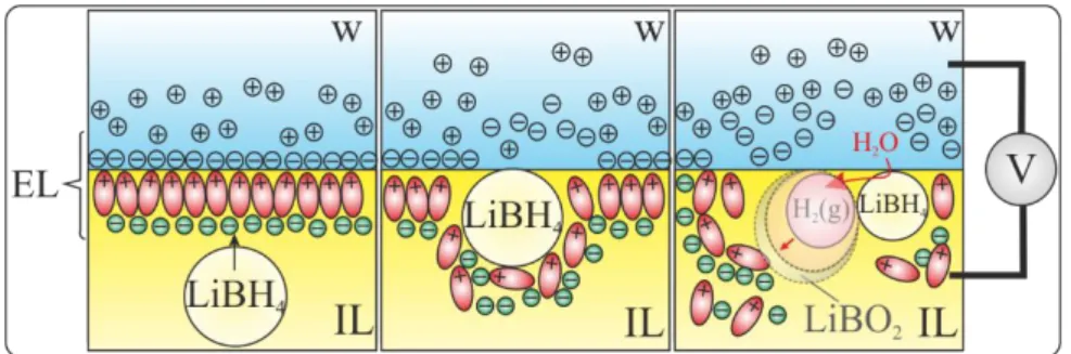
Figure 2: Proposed mechanism of NC adsorption at a w|IL interface with disruption of the
back-to-back electric layers (ELs) eliciting a change in the capacitive current. Upon LiBH4 NC
impact, an H2 bubble grows at the NC-w|IL interface with a layer of LiBO2 at the bubble
fron-tier.
Meanwhile, for the LiBH4 added black traces (B,C), negative current spikes, or
oscilla-tions, are observed towards negative potentials. Voltammetric current oscillations have been observed previously at w|o LLIs by Kakiuchi et al. [67-69] and others [70-72]. They were
attributed to the adsorption of ionic surfactants at w|o LLI leading to rapid fluctuations in the IT wave current signal near the species formal IT potential. A thermodynamic model suggested that negative currents would correspond to the adsorption of negatively charged species and vice versa for positively charged ones. In the present case, current spikes are still present, but no IT wave was observed after THF removal that could be associated with molecular adsorp-tion. Therefore, the current spikes may have another origin as they are reminiscent of those observed for NP impacts at ultramicroelectrodes [21-29] or micro-LLIs [30-34]. Since they are related to the presence of LiBH4 in the IL, and owing to its partial solubility, we propose that
the current spikes observed in Figure 1B,C are related to the presence of LiBH4 crystals,
sus-pended in P66614NTf2, which collide with the LLI through Brownian motion. Owing to the
strong reducing strength of LiBH4, when reaching the w|o interface, the LiBH4 crystals are
expected to undergo a complex 8-electron borohydride oxidation reaction (BOR) [73]:
LiBH4+ (2 + 𝑥)H2O → LiBO2∙ 𝑥H2O + 4H2 1
BOR is the overall reaction for harvesting H2 from borohydrides. BOR leads to the generation
of LiBO2 material, which is even less soluble in the IL phase, but which could transfer into the
aqueous phase without a priori charge transfer across the LLI. However, we propose that the overall reaction 1, or its consequence, disrupts the organized capacitive back-to-back electric layers, similar to the disruption seen with ionic surfactants [67-72]. Such LLI disruption may originate from the adsorption of LiBH4 crystals, as schematized in Fig. 2, but the formation of
LiBO2 crystals or the generation of H2 bubbles at the LLI would function equivalently. Uehara
et al. [74] recently investigated the interfacial formation of Au NPs at a
water|1,2-dichloro-ethane (w|DCE) interface through the Burst-Shiffrin method. They demonstrated BH4– transfer,
however, they employed a 1mM LiOH (pH 11) aqueous solution to inhibit the spontaneous reaction of BH4– with water. This is not the case here (pH 5-6 for MilliQ water). Therefore, we
hypothesize that LiBH4 NCs react as they contact or approach the w|P66614NTf2 interface, since
the P66614NTf2 is likely water saturated in the vicinity of the interface. This is why neither BH4–
ion nor NC transfer is observed. It is well known that the w|IL interface is well organized and can extend several ionic layers into the IL phase [75-79]; Fig. 2 has been drawn with this in mind. That the current spikes are negative may be owing to the release and adsorption of BH4–
in a similar manner as the adsorption of a negatively charged ionic surfactant as described by Kakiuchi [67-72] (see discussion above). Alternatively, the negative current may be due to en-hanced ionic conductivity due to solubilization of the LiBH4 salt and its constituent ions
occupying vacancies in the IL ionic layers [75-79]. In our proposed mechanism no electrons are exchanged across the LLI, since e– transfer from IL→w would elicit a positive current spike.
To investigate the presence and reactivity of LiBH4 NCs at interfaces, we engaged
dif-ferent microscopic methods. First, a 10µL aliquot of the LiBH4-P66614NTf2 solution prepared
above was added to dry, deoxygenated toluene (1mL) and mixed. A TEM grid was suspended in the solution for ~5min, then removed and dried under a flow of Ar. Fig. 3A,B show TEM images taken at two different locations within the sample, where the dark objects are LiBH4
NCs. These images indicate irregularly shaped NCs with high size polydispersity, ranging from <10nm to >150nm. A larger number of smaller NCs were observed during TEM imaging. This is thought to be owing to three factors: i) there is simply a lower amount of the large NC aggre-gates, ii) the larger NCs have difficulty adhering to the grid surface, iii) transfer of the NC-IL mixture to toluene alters the NC morphology. Particles from >50 images were measured along their longest axis and a size distribution profile developed (Fig. S2 in SI) and fit using a Gauss-ian curve with the peak providing a NC diameter of ~10nm. DLS analysis of the IL-NC solution provides a distribution of NCs (not shown) whose hydrodynamic diameter is centered rather at ~160nm. Larger particles generally mask smaller particle signals within DLS measurements, thus this result is consistent with the LiBH4 NCs polydispersity revealed by TEM.
Figure 3: [A-B] TEM images of LiBH4 NCs. [C-D] Backside absorbing layer optical
micros-copy (BALM) images taken at 63× magnification in a drop of IL solution containing 0 and 6mM LiBH4 in P66614NTf2, respectively.
Further insight into the presence and reactivity of NCs at interfaces was obtained from optical microscopies, which were performed in situ in real time at the interface between a Au layer and the IL phase. This is provided by the BALM technique (see SI Fig. S3), which is based on an ultrathin and highly absorbing gold layer deposited on a glass slide, mounted on an inverted microscope and lit from the bottom. The ~5nm thick Au layer acts as a pseudo-anti-reflective coating and allows imaging of nano-objects lying on its surface with high sensitivity. A nano-object lying on the surface disturbs the local refractive index and therefore the local reflectance at the nano-object-Au layer interface, appearing highly contrasted. BALM was then used to image the presence of LiBH4 NCs in P66614NTf2. Two drops (5µL each) of the LiBH4
-in-P66614NTf2 solutions were deposited on a BALM substrate. The first contained no LiBH4
(blank, Fig. 3C) and appears uncontrasted, as the solution does not contain NCs. After deposi-tion of the LiBH4-IL solution, the image reveals the presence of dark spots, as shown in Fig.
3D. It was also noted that increasing [LiBH4] causes a concomitant increase in the number of
spots. These black optical spots, often diffraction limited, indicate a local decrease in reflec-tance, which is due to local refractive index increase associated with the presence of a dielectric material at the Au-IL interface. We assume they manifest the presence of LiBH4 NCs or their
reaction product, LiBO2, through 1 with residual water. ILs are known to be hygroscopic and
will absorb moisture from the air, feeding 1.
The reactivity of the LiBH4 NCs was probed by BALM. Indeed, micro- or nano-bubbles
are also visible in BALM as the technique is sensitive to all local refractive index changes (1.0 and 1.4 for H2 and the IL, respectively). Therefore, H2 bubbles at the Au-IL interface appear as
more reflective (brighter) regions.
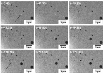
Fig. 4 presents a sequence of BALM images monitoring the formation of two bubbles (indicated by arrows) at the Au surface. These are characterized by the bright spots with radii in the range of 0.3-0.7µm. They last for several tens of seconds (experimentally from t=0 to t=48.35s for the first one) near the Au surface and move slowly (less than 1µm), likely because of the high IL viscosity and also because they are trapped at the Au-IL interface. Even though H2 is poorly soluble in ILs, the long persistence of the bubbles at the surface suggests that they
are anchored to a LiBH4 NC, which continuously fuels H2 bubble growth. It is also indicative
of the slow transformation rate of the LiBH4 NC, while we have not attempted to control the
H2O content of the IL. The dynamics of bubble disappearance was also tracked during such
movies (at 20fps). This disappearance stems from ending of LiBH4 reaction with H2O and
the Au surface. This is simultaneous with the quick (<0.8s from t=48.35s) expansion of a dark region on the Au surface of a dielectric material. The larger the bubble, the larger the dark region will be. Based on these observations, we suggest that this region is related to the re-lease/deposition of metaborate, LiBO2, which is generated during H2 evolution at the
bubble-IL interface and released as a phase transfer process to the more hydrophilic Au region at reac-tion complereac-tion. From a LiBO2 disc (assuming a thickness of 0.5nm), one can calculate the
radius for the originating LiBH4 NC, such that discs with rdisc=0.5-1.0µm would develop from
NCs with a radius rNC=80-120nm, which is in fair agreement with the NC sizes observed
mi-croscopically.
Figure 4: Sequence of BALM images showing two Bubbles (highlighted by arrows) impacting
the antireflective substrate. Images were taken in a drop of IL solution containing 6mM LiBH4.
LiBH4 NCs in P66614NTf2 were also imaged by darkfield optical microscopy (see SI Fig. S4).
Several scattering features are detected in the IL solutions, and their content increases gradually with LiBH4 content of the solution. However, these scattering spots cannot be unambiguously
differentiated from LiBH4 NCs, as frequently imaged above through TEM, or H2 bubbles
formed in the IL during the reaction between NCs and water molecules. Using the DLS deter-mined diameter as a guide, the NC concentration, cNC, was calculated through Eq. S3 [19, 20]
(see SI) assuming spherical particles. For example, cNC for 160nm Ø particles were calculated
to be 3×10¹⁴ and 8×10¹⁵NC L–1, for the overall effective [LiBH4]eff (sequestered as NCs +
sol-ubilized) of 20, and 600mM, respectively. This likely underestimates cNC, as the DLS cannot
These microscopic observations support, at least semi-quantitatively, the existence of LiBH4
NCs and their reactivity in an IL toward H2 generation, as suggested by 1. They also suggest
that this reaction may occur at interfaces.
As the reaction is driven by H2O, we tested this mechanism at a w|IL interface, via
electro-chemical monitoring of currents passing through this interface. For that purpose, chronoam-perometric (CA) curves were recorded at a micro-LLI at different [LiBH4]eff. Fig. 5A and inset
(a) show CA traces obtained by biasing the potential in Cell 1 at (Epzc – 0.050V) without LiBH4
(blank). In the presence of LiBH4 NCs, panels B-D for 10, 20, 50mM [LiBH4]eff, respectively,
current spikes are observed to increase in frequency with increasing [LiBH4]eff. The spike
pro-file is reminiscent of other nano-object impact recordings [19, 20]: a baseline current before, with a sudden onset current (spike) upon NP impact, followed by a decay period (deactivation). Peak durations (obtained from full-width-at-half-maximum curve fitting of the spike profile) averaged 0.09s with a maximum of 1.8-2s. Similar results were observed when Li2SO4 (aq) was
replaced with 5mM H2SO4.
Owing to the observation of NCs and H2 bubble generation in the IL, it is likely that as LiBH4
NCs in the IL phase contact the aqueous phase they undergo a similar reaction to that observed using BALM – i.e. 1. As proposed earlier (vide supra), the adsorption of either crystal phase or the generation of H2 bubbles at the interface may alter the interfacial double layer, resulting in
the observed current spike. It is proposed that the amount of charge displaced by these objects (Qc) at the interface is proportional to the volume of the LiBH4 NC impacting it (assuming a
sphere with radius rNC) [19, 28, 29]:
𝑄𝑐 ∝ 4 3𝜋𝑟NC 3 𝑧𝜌𝐹 𝑀𝑤 [2]
where z and F are the charge and Faraday constant, while Mw and ρ are the molecular weight
and density of LiBH4. The current transient, Jc, corresponds to the charge variation during the
NC adsorption (Jc=dQc/dt). From the integration of each baseline corrected current spike an
apparent value of rNC was evaluated assuming z≈1. Fig. 5E shows the histogram obtained for
rNC compiled across all [LiBH4]eff with a Gaussian curve fitting (red trace) centered at 40nm. A
mean rNC of 60nm was also determined from these data. Fig. S5 (SI) shows histograms of rNC
for each concentration and demonstrates that with increased [LiBH4]eff there is an increase in
the number of large (>100nm Ø) NC aggregates. It is possible however, that not all of the par-ticle necessarily interacts with the LLI and partial dissolution/reaction through 1 of the NC may
result. This combined with the high size polydispersity of the NCs explains the variability in current spike size. Furthermore, the associated baseline current noise is ~7-8pA (Fig. 5A inset (a)), which corresponds to an rNC≈15-18nm and represents the effective detection limit of the
potentiostat employed.
Figure 5: Chronoamperograms (CA) performed at (Epzc–0.050V) using Cell 1 with 0, 10, 20,
and 50mM [LiBH4]eff for panels A-D, respectively. Insets (a) and (b) show enhanced views of
curve A and a peak in curve C marked with an (*), respectively. E Histogram of rNC calculated
from Eq. 2 and by peak integration from the recorded CAs.
The peak signals here resemble more closely single NP impact events than CAs recorded for ionic surfactant adsorption [67-72]. The latter generates truly chaotic recordings, while what is observed here resemble discreet events.
𝑓 = 4𝐷NC𝑐NC𝑎 [3]
where DNC and cNC are the diffusion coefficient and concentration of NC in P66614NTf2, while
a is the radius of the LLI (12.5 µm). DNC≈0.3µm2 s–1 was calculated via the Stokes-Einstein
equation for an rNC = 60nm (used as a first approximation), cNC was calculated to be 3.6, 7.2,
and 18.1×10¹¹NC cm–3 for Fig. 5 panels B-D, respectively. This leads to a calculated frequency of impacts, f, of 0.2, 0.5, and 1.0s–1 compared to the observed values of 0.2, 0.5, and 0.6s–1. These are in fair agreement and support the size polydispersity evidenced using TEM and op-tics. Moreover, owing the NC reactivity their size is likely not static. Again, for comparison the frequency of H2 bubble adhesion (or dark spot formation) at the 25x20µm2 Au-IL BALM
mon-itored interface is about 0.015s–1 for 6mM [LiBH4]eff, which would indicate that both interfacial
phenomena are driven by the same limiting transport of LiBH4 NCs toward an interface.
CAs (SI, Fig. S6) were performed using Cell 1 with 5mM Li2SO4 (aq) and 600mM [LiBH4]eff
(P66614NTf2), but with potentials stepped from Epzc to (Epzc – 0.2V) or (Epzc + 0.2V). For the
former, an impact was recorded at f≥1s–1, while for the latter it was at f≈0.02s–1. This demon-strates a potential dependence on the impact frequency, which may be related to the IT/adsorp-tion of BH4– through release from the NC, similar to ionic surfactants [67-72], or the NC
zeta-potential. A zeta-potential of 34mV was determined for the NCs in P66614NTf2 from the DLS,
but a great deal of error was associated with this measurement (±0.250V), which should be considered a gross estimate. It may, however, explain the change in f with potential since neg-atively charged particles would be attracted by the positively biased LLI.
Finally, 1 suggests the generation of H2 upon LiBH4-NC approach to the w|IL interface and
micrometric H2 bubbles are indeed generated at a Au/IL interface, as optically recorded (vide
supra). To investigate this at the LLI we optically monitored, under darkfield illumination, the
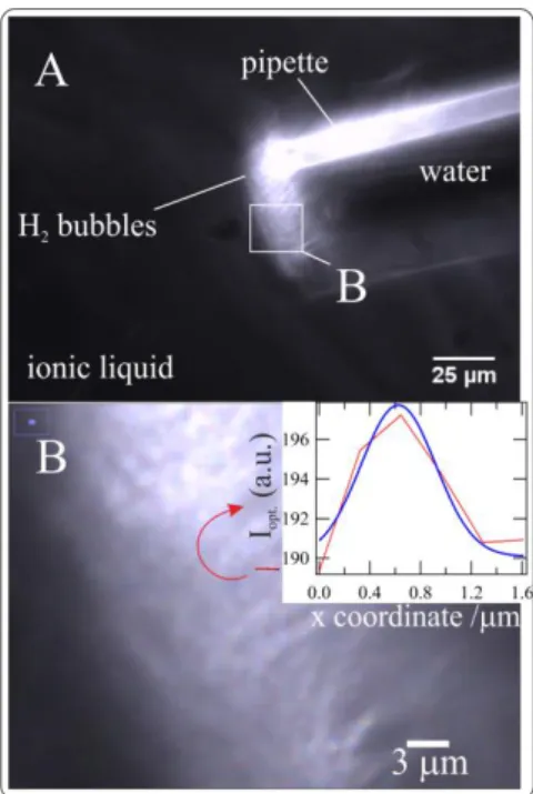
micro-LLI made by a pulled glass pipette containing the aqueous phase inserted into a home-made cell (SI, Fig. S7) containing the IL phase. Fig. 6A shows a still image at 40× magnification captured from a video taken at the pipette tip (inner tip diameter ~50µm), housing the aqueous phase with 5mM Li2SO4, immersed in a 20mM [LiBH4]eff P66614NTf2 solution. A layer of
effer-vescence can be seen at the pipette tip, which developed immediately upon immersion of the pipette into the IL phase, and is likely the formation of H2 bubbles according to 1. This means
that monitoring the w|IL interface is not possible. Bubbles were observed to rise from the tip and accumulate on the upper glass-slide surface (SI, Fig. S7); however, this process was slow and consistent with the long bubble residency-time on the Au-IL interface. The layer of H2
bubbles at the w|IL interface would lead to Marangoni-like effects, which are described as changes in surface tension at liquid-air or liquid|liquid interfaces [80] that in turn cause in-creased hydrodynamic flow, much faster than diffusion alone. Indeed, this may be used to ex-plain the increased number of larger current spikes (magnitude>0.4nA) observed at 50mM vs. 20 or 10mM [LiBH4]eff in Fig. 5B-D. With increased hydrodynamic flux larger NCs have
in-creased mobility and are more readily detected at the LLI.
Similarly, it is proposed that the disparity between the calculated and observed flux of NCs at ~Epzc is owing to two factors: (i) the gross estimate of [NC] due to their polydispersity; (ii)
an enhancement of the flux through H2-in-IL foam formation causing Marangoni-like effects.
Fig. 6B provides a close-up of the pipette tip and H2 foam. The red line (arrow) describes
the location from which a plot profile (inset) of the local scattered light intensity, Iopt., was taken,
with the x-coordinate corresponding to the red line length scale. This details the diameter of the bright-spot, ~1µm, and is consistent with the size of the H2 bubbles detected at the Au/IL
inter-face. It also corroborates H2 bubble formation close to the w|IL interface. The effervescent
re-gion corresponds to a dense rere-gion of bubbles. It first suggests that H2 is preferentially generated
in the IL phase, a diffuse region of bubbles is indicative of the partial solubility of H2O in the
IL. Over several tens of seconds this diffuse layer of H2 bubbles has a steady size, supporting
the long persistence of H2 bubbles also monitored, at the single bubble level, at the Au-IL
in-terface. Because the pipette was mounted horizontally (SI, Fig. S7), the bubbles were observed to detach slowly from the LLI, rise and accumulate at the top of the cell. Using a mass-transfer limited H2 dissolution rate analogous to Eq. 3 as a back-of-the-envelope calculation, with 𝐷H2(𝑔)
and 𝑐H2sat′d (saturated [H2]) of 10–6cm2 s–1 and ~2mM [81-83], along with a=25µm, one
esti-mates a rate of H2 evolution at 0.02pmol s–1. Considering the full foam region, Comsol
simula-tion (SI secsimula-tion 10) rather gives a rate of 0.04pmol s–1 of H2 generated (semispherical diffusion
Figure 6: A is a darkfield optical image of a pulled glass pipette tip containing a 5mM Li2SO4
aqueous solution immersed in P66614NTf2 containing 20mM [LiBH4]eff. B shows a close-up
im-age taken from A (indicated) of the H2 gas-in-IL foam field. Inset in B: local scattering light
intensity, Iopt., vs. an x-coordinate defined by the red line in B and describing a single H2 bubble;
fit using a Gaussian function (blue trace).
Similarly, Eq. 2 can be taken from the perspective of the charge displaced on either side of the w|IL interface as related to their respective Debye lengths, coupled to an effective surface area affected (A≈4πr2, using a sphere as a first approximation) and the current spike integral,
see SI section 11 for calculation details. In this way, the effected ‘radius’ was calculated to be ~1-2µm regardless of whether it was the IL or w side of the interface. This agrees well with the size of H2 bubbles recorded in Fig. 6.
It is then suggested that solutions of LiBH4 in P66614NTf2 can be used to deliver H2 at
reasonable rates; similar results are expected for LiBH4 in P8888Br, an organic ionic plastic
crys-tal (OIPC) [18]. In a typical GC column experiment, 0.4mL aliquots of 600mM [LiBH4]eff in
P66614NTf2 were placed into each of 5 sealed GC vials with the IL and headspace gases
main-tained under Ar. Next, 1µL of degassed H2O was added to the vials. The headspace of one of
the 5 vials was sampled every ~10min using a 250µL air-tight syringe and injected into a GC column in order to develop a profile of Δ[H2]/t. This protocol was repeated for the other
mate-rials (LiBH4 in P8888Br, LiBH4 + Au-NPs in P8888Br, etc.). A plot of [H2] in the headspace over
presence of Au or Pt NPs (see SI Fig. S10 for TEM images of the as-prepared NPs). Based on the results from Fig. 7, the presence of metal NPs within the IL or OIPC phase had little effect on H2 evolution. This is likely owing to the low diffusion coefficient (mass transport) of H2O
and NPs in the IL reducing the observed reaction rate. After 10 and 20min, 20 and 50%, respec-tively, of the theoretical H2 has been liberated. This is slow compared to, for example, NaBH4
dissolved in water in combination with certain accelerators, as demonstrated by Schlensinger
et al. [84]. This does demonstrate, however, that the IL and OIPC media can be support phases
for LiBH4/H2 storage, but reaction rates are likely limited by their relatively high viscosity
(dif-fusivity and solubility of H2 within these matrices) compared to molecular solvents. During
sampling the OIPC was a solid/plastic and hence this indicates possible increased activity of the OIPC film vs. the IL, since in the former, the H2O droplet rests on the solids surface while
in the latter the droplet is fully immersed in the liquid phase. This would result in less surface contact for the OIPC case, but more needs to be done to investigate this point; this is beyond the scope the present work.
Figure 7: Plot of the concentration of H2 (mM) evolved in the headspace of a GC vial
contain-ing either P66614NTf2, an ionic liquid (IL), or P8888Br, an organic ionic plastic crystal (OIPC)
over time (min), with (a) 600mM of [LiBH4]eff in IL, (b) a + Au NPs, (c) 600mM LiBH4 in
OIPC, (d) c + Au NPs, and (e) a + Pt NPs. TEM images of NPs are shown in Fig. S10 (SI).
For comparison purposes, the flux of H2 generated by the pipette was extrapolated to
that of the surface area of the 1µL water droplet deposited in the vial (r≈620µm) for the GC experiment. The GC rate was further corrected, based on the difference in LiBH4 concentration
(20 vs. 600mM, i.e. factor 30) between the pipette and GC experiments. From the pipette flux of H2, one expects a rate of 0.1nmol s–1 H2, while during the GC experiment 0.2nmol s–1 in the
4.0 Conclusions
The convergence of multiple techniques, ranging from ex situ TEM to in situ high-res-olution optical microscopies and electrochemical stochastic impacts experiments at a w|IL in-terface, evidence the formation and reactivity of LiBH4 NCs in an IL medium. TEM
measure-ments are not ideal, since transfer of the IL-inorganic salt solution to a molecular solvent, in order to facilitate sample deposition on the TEM grid, undoubtedly alters the NC morphology. At the same time, the TEM beam can be destructive to certain samples and thus may not be innocent either. Thus, the use of high-resolution microscopies, such as BALM and darkfield, were integral in establishing the presence and reactivity of LiBH4 NCs suspended in an IL,
particularly at different interfaces (Au/IL and w|IL). The solubility of inorganic salts in ILs is an emerging field of study, especially with ILs and OIPCs being proposed liquid/solid electro-lyte phases for lithium ion batteries. As highlighted with this work, this is another critical phys-ical chemphys-ical property of ILs that will have to be tailored to meet specific application needs.
An attempt has been made herein to extend electrochemical nano-impact studies beyond model systems (e.g. metal NPs or insulating polymer NPs). In the present case, the proposed mechanism is based on charge displacement or adsorption altering the back-to-back electric layers during NC impact, which in turn creates a change in the interfacial capacitance. This agrees well with the adsorption of charged species, such as ionic surfactants, as demonstrated in the past. The frequency of impacts was in relatively good agreement with the calculated value considering the high polydispersity of the NCs and Marangoni effects through H2-in-IL
mi-cro/nano foams, which generates an increased hydrodynamic flow.
Critically, the formation of H2-in-IL foams represents a possible facile method for the
generation of H2 bubbles in an IL phase whose nucleation is of interest in heterogeneous catalyst
design [85-87] and should be of particular significance for LLI solar fuel generation (i.e. H2 or
O2 evolution/reduction reactions) moving forward.
Acknowledgements
We are grateful for financial support by the Agence Nationale pour la Recherche (NEO-CASTIP-ANR-15-CE09-0015-02). T.J.S. would like to gratefully acknowledge funding through a Marie-Skłodowska Curie Action incoming post-doctoral fellowship (MSCA-IF, pro-ject #DLV-708814). Partial financial support to M. R. from the Institut Universitaire de France (IUF) is gratefully thanked. T.J.S would also like to thank Pr. Alexa Courty and Dr. Guillaume Wang for help in TEM imaging.
5.0 References
[1] M. Paskevicius, L.H. Jepsen, P. Schouwink, R. Cerny, D.B. Ravnsbaek, Y. Filinchuk, M. Dornheim, F. Besenbacher, T.R. Jensen, Chem. Soc. Rev., 46 (2017) 1565-1634.
[2] H.-W. Li, Y. Yan, S.-i. Orimo, A. Züttel, C.M. Jensen, Energies, 4 (2011) 185.
[3] A. Doroodian, J.E. Dengler, A. Genest, N. Rösch, B. Rieger, Angew. Chem. Int. Ed., 49 (2010) 1871-1873.
[4] R. Mohtadi, A. Remhof, P. Jena, J. Phys.: Condens. Matter, 28 (2016) 353001/353001-353001/353019.
[5] J. Ma, N.A. Choudhury, Y. Sahai, Renew. Sust. Energy Rev., 14 (2010) 183-199.
[6] S.C. Amendola, P. Onnerud, M.T. Kelly, P.J. Petillo, S.L. Sharp-Goldman, M. Binder, J. Power Sources, 84 (1999) 130-133.
[7] S. Wegner, C. Janiak, Top. Curr. Chem., 375 (2017) 1-32.
[8] G. Durga, A. Mishra, Ionic Liquids: Industrial Applications, in: Encyclopedia of Inorganic and Bioinorganic Chemistry, John Wiley & Sons, Ltd, 2011.
[9] A.B. Pereiro, J.M.M. Araújo, F.S. Oliveira, J.M.S.S. Esperança, J.N. Canongia Lopes, I.M. Marrucho, L.P.N. Rebelo, J. Chem. Thermodyn., 55 (2012) 29-36.
[10] C. Janiak, Top. Organomet. Chem., 51 (2015) 17-53.
[11] J.D. Scholten, B.C. Leal, J. Dupont, ACS Catalysis, 2 (2010) 184-200.
[12] A. Banerjee, R.W.J. Scott, Au, Ag, and Cu Nanostructures, in: Nanocatalysis in Ionic Liquids, Wiley-VCH, 2016, pp. 97-123.
[13] A. Banerjee, R. Theron, R.W.J. Scott, Chem. Commun., 49 (2013) 3227-3229. [14] A. Banerjee, R.W.J. Scott, Green Chem., 17 (2015) 1597-1604.
[15] M. Antonietti, D. Kuang, B. Smarsly, Y. Zhou, Angew. Chem. Int. Ed., 43 (2004) 4988-4992.
[16] X. Chen, S.L. Chew, F.M. Kerton, N. Yan, Green Chem., 16 (2014) 2204-2212. [17] T.S. Hansen, J. Mielby, A. Riisager, Green Chem., 13 (2011) 109-114.
[18] T.J. Stockmann, P.D. Boyle, Z. Ding, Catal. Today, 295 (2017) 89-94.
[19] S.V. Sokolov, S. Eloul, E. Katelhon, C. Batchelor-McAuley, R.G. Compton, Phys. Chem. Chem. Phys., 19 (2017) 28-43.
[20] P.H. Robbs, N.V. Rees, Phys. Chem. Chem. Phys., 18 (2016) 24812-24819.
[21] B.M. Quinn, P.G. van't Hof, S.G. Lemay, J. Am. Chem. Soc., 126 (2004) 8360-8361. [22] J.E. Dick, C. Renault, A.J. Bard, J. Am. Chem. Soc., 137 (2015) 8376-8379.
[23] X. Xiao, A.J. Bard, J. Am. Chem. Soc., 129 (2007) 9610-9612.
[24] B.-K. Kim, J. Kim, A.J. Bard, J. Am. Chem. Soc., 137 (2015) 2343-2349. [25] H.S. Toh, R.G. Compton, Chem. Sci., 6 (2015) 5053-5058.
[26] E.E.L. Tanner, K. Tschulik, R. Tahany, K. Jurkschat, C. Batchelor-McAuley, R.G. Compton, J. Phys. Chem. C, 119 (2015) 18808-18815.
[27] A. Feng, W. Cheng, R.G. Compton, Chem. Sci., 7 (2016) 6458-6462.
[28] V. Brasiliense, A.N. Patel, A. Martinez-Marrades, J. Shi, Y. Chen, C. Combellas, G. Tessier, F. Kanoufi, J. Am. Chem. Soc., 138 (2016) 3478-3483.
[29] E. Kätelhön, E.E.L. Tanner, C. Batchelor-McAuley, R.G. Compton, Electrochim. Acta, 199 (2016) 297-304.
[30] E. Laborda, A. Molina, V.F. Espín, F. Martínez-Ortiz, J. García de la Torre, R.G. Compton, Angew. Chem. Int. Ed., 56 (2017) 782-785.
[31] T.J. Stockmann, L. Angelé, V. Brasiliense, C. Combellas, F. Kanoufi, Angew. Chem. Int. Ed., 56 (2017) 13493-13497.
[32] D.A. Robinson, A.M. Kondajji, A.D. Castañeda, R. Dasari, R.M. Crooks, K.J. Stevenson, J. Phys. Chem. Lett., 7 (2016) 2512-2517.
[33] R. Dasari, D.A. Robinson, K.J. Stevenson, J. Am. Chem. Soc., 135 (2013) 570-573. [34] T.R. Bartlett, C. Batchelor-McAuley, K. Tschulik, K. Jurkschat, R.G. Compton,
ChemElectroChem, 2 (2015) 522-528.
[35] M. Heyrovsky, J. Jirkovsky, M. Struplova-Bartackova, Langmuir, 11 (1995) 4300-4308. [36] M. Heyrovsky, J. Jirkovsky, M. Struplova-Bartackova, Langmuir, 11 (1995) 4309-4312. [37] M. Heyrovsky, J. Jirkovsky, B.R. Mueller, Langmuir, 11 (1995) 4293-4299.
[38] M. Heyrovsky, J. Jirkovsky, Langmuir, 11 (1995) 4288-4292.
[39] H. Deng, J.E. Dick, S. Kummer, U. Kragl, S.H. Strauss, A.J. Bard, Anal. Chem., 88 (2016) 7754-7761.
[40] B.-K. Kim, A. Boika, J. Kim, J.E. Dick, A.J. Bard, J. Am. Chem. Soc., 136 (2014) 4849-4852.
[41] W. Cheng, R.G. Compton, Angew. Chem. Int. Ed., 54 (2015) 7082-7085.
[42] J.-F. Lemineur, J.-M. Noël, C. Combellas, D. Ausserré, F. Kanoufi, Faraday Discuss., (2018).
[43] J.-F. Lemineur, J.-M. Noël, D. Ausserré, C. Combellas, F. Kanoufi, Angew. Chem. Int. Ed., 57 (2018) 11998-12002.
[44] V. Brasiliense, J. Clausmeyer, P. Berto, G. Tessier, C. Combellas, W. Schuhmann, F. Kanoufi, Anal. Chem., 90 (2018) 7341-7348.
[45] C. Schopf, A. Wahl, A. Martín, A. O’Riordan, D. Iacopino, J. Phys. Chem. C, 120 (2016) 19295-19301.
[46] L. Xiao, Y. Qiao, Y. He, E.S. Yeung, Anal. Chem., 82 (2010) 5268-5274.
[47] A.N. Patel, A. Martinez-Marrades, V. Brasiliense, D. Koshelev, M. Besbes, R. Kuszelewicz, C. Combellas, G. Tessier, F. Kanoufi, Nano Lett., 15 (2015) 6454-6463. [48] X. Li, L. Ren, J. Dunevall, D. Ye, H.S. White, M.A. Edwards, A.G. Ewing, ACS Nano, 12
(2018) 3010-3019.
[49] V. Brasiliense, J. Clausmeyer, A.L. Dauphin, J.-M. Noël, P. Berto, G. Tessier, W. Schuhmann, F. Kanoufi, Angew. Chem. Int. Ed., (2017) n/a-n/a.
[50] R. Hao, Y. Fan, B. Zhang, J. Am. Chem. Soc., 139 (2017) 12274-12282.
[51] Y. Yu, V. Sundaresan, S. Bandyopadhyay, Y. Zhang, M.A. Edwards, K. McKelvey, H.S. White, K.A. Willets, ACS Nano, 11 (2017) 10529-10538.
[52] X. Shan, I. Díez-Pérez, L. Wang, P. Wiktor, Y. Gu, L. Zhang, W. Wang, J. Lu, S. Wang, Q. Gong, J. Li, N. Tao, Nature Nanotechnology, 7 (2012) 668.
[53] C.J. Bradaric, A. Downard, C. Kennedy, A.J. Robertson, Y. Zhou, Green Chem., 5 (2003) 143-152.
[54] T.J. Stockmann, Y. Lu, J. Zhang, H.H. Girault, Z. Ding, Chem. Eur. J., 17 (2011) 13206-13216.
[55] T.J. Stockmann, A.-M. Montgomery, Z. Ding, Can. J. Chem., 90 (2012) 836-842. [56] Z. Samec, J. Langmaier, T. Kakiuchi, Pure Appl. Chem., 81 (2009) 1473-1488. [57] T.J. Stockmann, Z. Ding, Phys. Chem. Chem. Phys., 14 (2012) 13949-13954. [58] T.J. Stockmann, Z. Ding, J. Phys. Chem. B, 116 (2012) 12826-12834.
[59] T.J. Stockmann, R. Guterman, P.J. Ragogna, Z. Ding, Langmuir, 32 (2016) 12966–12974. [60] N. Tsujioka, S. Imakura, N. Nishi, T. Kakiuchi, Anal. Sci., 22 (2006) 667-671.
[61] B.M. Quinn, Z. Ding, R. Moulton, A.J. Bard, Langmuir, 18 (2002) 1734-1742. [62] T.J. Stockmann, Z. Ding, J. Electroanal. Chem., 649 (2010) 23-31.
[63] T. Kakiuchi, Anal. Chem., 79 (2007) 6442-6449.
[64] N. Nishi, H. Murakami, S. Imakura, T. Kakiuchi, Anal. Chem., 78 (2006) 5805-5812. [65] R.E. Del Sesto, C. Corley, A. Robertson, J.S. Wilkes, J. Organomet. Chem., 690 (2005)
2536-2542.
[66] T.J. Stockmann, J. Zhang, J.C. Wren, Z. Ding, Electrochim. Acta, 62 (2012) 8-18. [67] Y. Kitazumi, T. Kakiuchi, Langmuir, 25 (2009) 10829-10833.
[68] T. Kakiuchi, M. Chiba, N. Sezaki, M. Nakagawa, Electrochem. Commun., 4 (2002) 701-704.
[69] T. Kakiuchi, J. Electroanal. Chem., 536 (2002) 63-69.
[70] M. Chowdhury, R. Kataky, ChemPhysChem, 17 (2016) 105-111.
[71] M.A. Méndez, Z. Nazemi, I. Uyanik, Y. Lu, H.H. Girault, Langmuir, 27 (2011) 13918-13924.
[72] M.A. Méndez, B. Su, H.H. Girault, J. Electroanal. Chem., 634 (2009) 82-89.
[73] M.J.F. Ferreira, L. Gales, V.R. Fernandes, C.M. Rangel, A.M.F.R. Pinto, Int. J. Hydrogen Energy, 35 (2010) 9869-9878.
[74] A. Uehara, S.G. Booth, S.Y. Chang, S.L.M. Schroeder, T. Imai, T. Hashimoto, J.F.W. Mosselmans, R.A.W. Dryfe, J. Am. Chem. Soc., 137 (2015) 15135-15144.
[75] Y. Yasui, Y. Kitazumi, R. Ishimatsu, N. Nishi, T. Kakiuchi, J. Phys. Chem. B, 113 (2009) 3273-3276.
[76] M.V. Fedorov, A.A. Kornyshev, Chem. Rev., 114 (2014) 2978-3036.
[77] N. Georgi, A.A. Kornyshev, M.V. Fedorov, J. Electroanal. Chem., 649 (2010) 261-267. [78] M.V. Fedorov, N. Georgi, A.A. Kornyshev, Electrochem. Commun., 12 (2010) 296-299. [79] d.E.E. Alvarez, S.D. S., A.D.W. M., Angew. Chem. Int. Ed., 54 (2015) 14903-14906. [80] S. Berg, Physics of Fluids, 21 (2009) 032105.
[81] Z. Lei, C. Dai, B. Chen, Chem. Rev., 114 (2014) 1289-1326.
[82] J. Jacquemin, P. Husson, V. Majer, M.F. Costa Gomes, J. Solution Chem., 36 (2007) 967-979.
[83] D. Morgan, L. Ferguson, P. Scovazzo, Industrial & Engineering Chemistry Research, 44 (2005) 4815-4823.
[84] H.I. Schlesinger, H.C. Brown, A.E. Finholt, J.R. Gilbreath, H.R. Hoekstra, E.K. Hyde, J. Am. Chem. Soc., 75 (1953) 215-219.
[85] Y. Liu, M.A. Edwards, S.R. German, Q. Chen, H.S. White, Langmuir, 33 (2017) 1845-1853.
[86] Q. Chen, L. Luo, H.S. White, Langmuir, 31 (2015) 4573-4581.
[87] Q. Chen, L. Luo, H. Faraji, S.W. Feldberg, H.S. White, J. Phys. Chem. Lett., 5 (2014) 3539-3544.
![Figure 1: Cyclic voltammograms at a w|P 66614 NTf 2 LLI using Cell 1 (Exp. Sect.) with 5mM Li 2 SO 4 (aq) and 0, 20, and 600mM [LiBH 4 ] for curves A, B, and C, respectively](https://thumb-eu.123doks.com/thumbv2/123doknet/15017299.681759/8.892.292.653.101.649/figure-cyclic-voltammograms-using-cell-sect-curves-respectively.webp)
![Figure 3: [A-B] TEM images of LiBH 4 NCs. [C-D] Backside absorbing layer optical micros- micros-copy (BALM) images taken at 63× magnification in a drop of IL solution containing 0 and 6mM LiBH 4 in P 66614 NTf 2 , respectively](https://thumb-eu.123doks.com/thumbv2/123doknet/15017299.681759/11.892.266.627.662.1021/figure-backside-absorbing-optical-magnification-solution-containing-respectively.webp)
![Figure 5: Chronoamperograms (CA) performed at (E pzc –0.050V) using Cell 1 with 0, 10, 20, and 50mM [LiBH 4 ] eff for panels A-D, respectively](https://thumb-eu.123doks.com/thumbv2/123doknet/15017299.681759/15.892.321.583.232.804/figure-chronoamperograms-performed-using-cell-libh-panels-respectively.webp)
![Figure 7: Plot of the concentration of H 2 (mM) evolved in the headspace of a GC vial contain- contain-ing either P 66614 NTf 2 , an ionic liquid (IL), or P 8888 Br, an organic ionic plastic crystal (OIPC) over time (min), with (a) 600mM of [LiBH 4 ] eff](https://thumb-eu.123doks.com/thumbv2/123doknet/15017299.681759/19.892.348.591.558.789/figure-concentration-evolved-headspace-contain-contain-organic-plastic.webp)