HAL Id: hal-00569650
https://hal.archives-ouvertes.fr/hal-00569650
Submitted on 25 Feb 2011HAL is a multi-disciplinary open access archive for the deposit and dissemination of sci-entific research documents, whether they are pub-lished or not. The documents may come from teaching and research institutions in France or abroad, or from public or private research centers.
L’archive ouverte pluridisciplinaire HAL, est destinée au dépôt et à la diffusion de documents scientifiques de niveau recherche, publiés ou non, émanant des établissements d’enseignement et de recherche français ou étrangers, des laboratoires publics ou privés.
Dynamical plasma study during CaCu3Ti4O12 and
Ba0.6Sr0.4TiO3 pulsed laser deposition by local
thermodynamic equilibrium modelling
Jean-François Lagrange, J. Hermann, J Wolfman, O Motret
To cite this version:
Jean-François Lagrange, J. Hermann, J Wolfman, O Motret. Dynamical plasma study during CaCu3Ti4O12 and Ba0.6Sr0.4TiO3 pulsed laser deposition by local thermodynamic equilibrium modelling. Journal of Physics D: Applied Physics, IOP Publishing, 2010, 43 (28), pp.285202. �10.1088/0022-3727/43/28/285202�. �hal-00569650�
Dynamical plasma study during CaCu
3Ti
4O
12and
Ba
0.6Sr
0.4TiO
3Pulsed Laser Deposition by Local
Thermodynamic Equilibrium modelling
J.F. Lagrange1, J. Hermann2, J. Wolfman1, O. Motret11
Laboratoire d'Electrodynamique des Matériaux Avancés (LEMA), UMR 6157 CNRS-CEA, Université François Rabelais de Tours, Faculté des Sciences & Techniques, Parc Grandmont - bât. E – 37200 Tours, France
2
Laboratoire Lasers, Plasmas et Procédés Photoniques (LP3), UMR 6182 CNRS, Université Aix-Marseille II, 163 Avenue de luminy, C. 917 - 13288 Aix-Marseille, France
Abstract
We performed space- and time- resolved plasma diagnostics during pulsed laser deposition of CaCu3Ti4O12(CCTO) and Ba0.6Sr0.4TiO3(BSTO) thin films. A KrF excimer laser irradiation at 248 nm with 25 ns pulse duration irradiates targets with a fluence varying from 1 to 2 J cm-2 under a oxygen pressure varying from 5 to 30 Pa. The plasma is shown to be optically thick and strongly non-uniform during the early expansion stage and the resonance lines Ca II393 and 396 nm are strongly self-reversed during this time. Plasma temperature, electron density and relative elemental concentrations were obtained by comparing the experimental emission spectra to the spectral radiance computed for a non-uniform plasma in local thermal
equilibrium. In this way, it was possible to evaluate very low concentrations of pollutants present in irradiated samples.
1. Introduction
In order to drastically reduce more and more the space taken up by electronic components in mobile technology, and in particular by capacitor components, many studies have been undertaken on new oxide ceramic structures with very high dielectric constants (high-K materials) as CCTO or BSTO, and on the transfer of their properties from bulk structure to thin film. Several techniques of thin films deposition have been developed during the last 20 years as Physical Vapour Deposition (PVD), Chemical Vapour Deposition (CVD), or Pulse Laser Deposition (PLD). Among these techniques, PLD presents the advantage of epitaxial growth of films congruent with the target. Elsewhere PLD is suitable for exploratory studies, due to its good deposition thickness control which also allows quick test of new component structures.
Informations about deposited film structures are obtained by ex-situ analytical techniques such as X-ray diffraction, scanning electron microscopy (SEM), transmission electron microscopy (TEM) or impedance spectroscopy. In addition the spectroscopic study of plasma, which is the transient stage of thin film deposition, may provide interesting in-situ information, as specie spreading and densities, plasma temperature or spatial development of the plume. Those informations can be correlated to the produced film analysis, in order to optimize the deposition process. Thanks to optical emission spectroscopy, it is possible to detect presence of very weak quantities of pollutant species (few tens ppm) which may badly affect film properties.
Laser-induced plasmas are known to be non-uniform. These plasmas show strong temperature and density gradients, which affect the shape of line profiles, leading to the so-called self-reversed lines. Self-reversed lines were studied in many works [1-7], they allow to estimate key parameters of
plasma, as electronic density or gas temperature. On one hand, most studies have been conducted on metallic targets generating plasmas composed by single specie and, in these cases only self-reversed lines were taken into account for plasma simulation [5,8-11]. In that case, the non-uniformity of the plasma was taken into account either by considering gradients of temperature and density from the core to the periphery, or by modelling the plasma in many concentric and uniform layers. On the other hand, for multi-component targets all species has to be taken into account in the calculated spectra in order to obtain a correct plasma simulation.
In this work, investigation by optical emission spectroscopy has been done on CCTO and BSTO ablated at moderate fluence. Moreover plume speed was given by imaging during plasma expansion. The simulation used in this study was based on a non-uniform LTE plasma and calculated for the spectral radiance in the whole UV-Visible-NIR range [12]. Computation of spectra was used for plasma characterization, in particular for some ionic species which profile show self-reversion. This model was also efficient for pollutant species identifications and their concentration estimations.
2. Experimental set-up
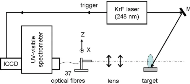
Ablation of oxide ceramic samples is performed using a KrF excimer laser (GSI Lumonics, model M888) that was operated at a wavelength of 248 nm at a repetition rate of 10 Hz. The laser generated pulses of 25 ns duration and a maximum energy of 850 mJ. After focusing with a UV fused silica lens of 320 mm focal length to a spot of about 3.3 mm2diameter, a fluence ranging from 1 to 2 J cm-2was incident on the sample’s surface. The samples were placed in a vacuum chamber of a residual pressure of about 1×10⁻⁶Pa. During the experiments, the chamber was filled with oxygen at a pressure that was varied from 5 to 30 Pa. The samples were continuously translated in order to avoid deep drilling. Spectral acquisition were done via two lenses (see figure 1) forming a 1:3 image of plasma onto an aligned and ordered bundle of 37 UV-visible optical fibres fixed on an XZ motorized stage. The bundle is set up on the entrance slit of an imaging spectrometer (Acton, model SP750i, 750 mm focal length). Spectra were recorded with two diffraction gratings of 2400 lines/mm or 1200 lines/mm, with a spectral resolution at full width at half maximum (FWHM) of 25 pm and 47 pm respectively at 498 nm, with an entrance slit of 30 µm. As diameter of each optical fibre is 200 µm and taking into account the magnification, the average plasma scanning resolution is 660 µm. An intensified charge-coupled device (ICCD) camera (Princeton Instruments, model PIMAX2, 1024×1024 pixels of 12.8 µm pixel size) is mounted on the output of the spectrometer and operates in time-gated mode. The camera is synchronised using the laser trigger-output signal. For delays with respect to the laser pulse up to 500 ns, the emission spectrum was recorded with a gate width of 10 ns to follow fast plasma propagation with a high temporal resolution. Plasma propagation was imaged with the previous camera equipped with UV-visible lens (Pentax, model B7838-UV).
3. Simulation model
The plasma generated by the laser ablation of the target material presents strong density and temperature gradients, in particular during its early expansion stage. In addition, according to the large plasma density, self-absorption plays a significant role and so-called self-reversed resonance lines characterize the plasma emission. A good approximation to describe this behaviour is to consider a plasma divided in two uniform zones: a core of high temperature and density, and a surrounding peripheral zone at lower temperature and density. In that case, the spectral radiance obtained by integrating the radiation transport equation is given by [5]:
1 1 1 2 2 2 2 2 2 ( , ) ( , ) 1 2 1 1 ( , ) 2 2 ( , , ) ( , ) (1 ) ( , ) (1 ) T L T L T L B T T U T e e U T e α λ α λ α λ λ λ λ − − − = − + − (1)
where the subscripts “1” and “2” indicate the values corresponding to the core and the periphery of the plasma respectively, T is the plasma temperature and L the dimension of the plasma zone in the observation direction. The blackbody spectral radiance is given by Planck’s law:
2 5 2 1 ( , ) ehc kT 1 hc U λ T λ λ = − (2)
and the absorption coefficient is determined by:
2
0 0
( , )T r f n Plu l ( , ) 1 exp hc
kT
α λ =π λ λ λ − −λ (3)
Here, r0 classical electron radius, h Planck’s constant, c the vacuum light velocity, flu the absorption oscillator strength and n the lower level population density of the transition, andl P(λ λ0, ) the normalized Voigt profile centred on λ0.
In equation (1), the first term corresponds to the radiation from the core region, which may be re-absorbed by the peripheral region. The second term is relative to photons emitted from the peripheral zone.
Three successive stages can be distinguished to describe the dynamics of the laser-produced plasma: - For short delay times (a few nanoseconds), density and temperature gradients are very strong: the plasma core is very dense and hot with a large optical thickness leading to a blackbody-like emission spectrum. This core is surrounded by a colder and mainly absorbing peripheral thin region.
- After the plume expansion during a time of a few tens of nanoseconds, the optical thickness of the plasma diminishes, and the emission spectrum is well described by equation (1) that takes into account the spatial gradients of plasma temperature and density.
- For a longer time (over several hundred of ns), the density and temperature gradients are reduced and the plasma can be approximated by a unique uniform zone:
(
)
(
( , ))
( , ) , 1 T L
B λ T =U λ T −e−α λ (4)
Figure 2 presents three simulated spectra of CCTO plume corresponding to the three typical behaviours detailed above:
- (a): absorption profile shapes over a global blackbody-like spectrum appearance, simulated by two uniform zones.
- (b): a non-uniform plasma simulated by two uniform zones. - (c): a uniform plasma
Parameters used, to build those spectra, are listed in table 1. We can note that the spectral shape is strongly dependant on plasma parameters, which makes easier estimation of plasma characteristics.
315 316 317 318 319 320 1x10¹³ 3x10¹³ C a I TiII T i II T i II T i II C a II T i II C a I TiII T i II C a II C a II T i II T i II T i I T i II T i II T i I Cu I T i II T i II
(c)
Wavelength (nm)
0 4x10¹⁴ 0 2x10¹⁵ 4x10¹⁵(a)
S
p
e
c
tr
a
l
ra
d
ia
n
c
e
(W
m
3s
r
-1)
(b)
Figure 2. Plasma parameter adjustments for three typical behaviours of CCTO PLD plasma.
Table 1. Plasma parameters from simulated spectra of figure 2.
Spectrum T1(K) T2(K) Ne1(cm-3) Ne2(cm-3) Thickness (mm) (a) 18000 12000 5x10¹⁸ 1x10¹⁷ L1 = L2 = 1 (b) 12000 8000 2x10¹⁷ 5x10¹⁶ L1 = L2 = 1
(c) 8000 - 2x10¹⁵ - L = 2
4. Experimental results
4.1. Space and time behaviour of CCTO panache
Fast imaging was used to characterize the expansion dynamics of the plume. Figure 3 presents images recorded with a fluence of 1.1 J cm-2 at different times after laser impact with an exposure time of 50 ns. The initial speed was estimated at about 1.2×10⁴m s-1, value in good agreement with other works led in comparable experimental conditions [13,14]. No speed difference was observed either in terms of mass or between atoms and ions of considered element. These behaviours can be attributed to the low atomic mass difference between titanium and calcium and to the low charge of space generated by our plasmas at low fluence, respectively.
Figure 3. CCTO plasma expansion under 30 Pa of O2, with a fluence of 1.1 J cm-2 and an oxygen pressure of 30 Pa. Acquisition time gate∆t = 50 ns.
For a pertinent plasma characterization it is necessary to choose a narrow spectral range including atomic and ionic species. Mainly produced in colder zones, atomic species are relevant indicators of peripheral zone, whereas ionic species qualify hotter zone as it can be in core plume region.
For our experimental conditions, spectra show neutral and singly charged species. Molecular spectra of TiO were detected, but without sufficient intensity for a spectroscopic study. The spectral window 393-398 nm contain Ti I lines and Ca II lines, and was retained as spectral range for analysis. In addition, observed Ca II lines are especially interesting for their large Stark widths, useful for electronic density estimations from both regions. Atomic data for lines present in the studied spectral range are listed in table 2.
Table 2. Wavelength λ0, transition probability Aul, lower and upper level transition energy Eland Eu, total electronic angular momentum of the lower and upper level Jland Ju, lower and upper level statistical weight gl and gu, Stark width w at Ne=1017cm-3, Stark shift d, for spectral lines emitted from the CCTO plasma in the spectral range between 393 and 398 nm.
λ0 (nm) Aul (×106s-1) El (cm-1) Eu (cm-1) Config. Lower level Config. Upper level Term Lower level Term Upper level Jl Ju gl gu w [15] (nm) d [15] (nm) Ca II 393.366 147 0 25 414.400 3d24s2 3d2(3P)4s4p(3P0) a3F y5D0 1/2 3/2 2 4 0.019 -0.005 Ti I 393.424 0.45 386.874 25 797.600 3p64s 3p64p 2S 2P0 4 3 9 7 - -Ti I 394.778 9.6 170.132 25 493.722 3d24s2 3d2(1D)4s4p(3P0) a3F z3P0 3 2 7 5 - -Ti I 394.867 48.5 0 25 317.813 3d24s2 3d3(4F)4p a3F y3D0 2 1 5 3 - -Ti I 395.634 30 170.132 25 438.898 3d24s2 3d2(1D)4s4p(3P0) a3F y3D0 3 2 7 5 - -Ti I 395.821 40.5 386.874 25 643.695 3d24s2 3d2(3P)4s4p(3P0) a3F y3D0 4 3 9 7 - -Ti I 396.285 4.13 0 25 227.217 3d24s2 3d2(3F)4s4p(1P0) a3F y3F0 2 3 5 7 - -Ti I 396.427 3.09 170.132 25 388.334 3d24s2 3d2(3F)4s4p(1P0) a3F y3F0 3 4 7 9 - -Ca II 396.847 140 0 25 191.510 3p64s 3p64p 2S 2P0 1/2 1/2 2 2 0.016 -0.004
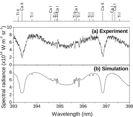
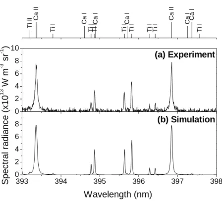
Two experimental spectra were recorded, one at early time close to the sample’s surface (100 ns, 0.7 mm), and an other at mean time with higher z-position (390 ns, 4 mm), and their associated simulated spectra were presented on figure 4 and figure 5 respectively, with there associated simulation parameters on table 3 and table 4 respectively. Plasma thicknesses were estimated according to panache imaging measurements. At short delay time (figure 4(a)), plasma has a behaviour close to a hot blackbody surrounded by a colder peripheral zone, it was well simulated by considering two uniform zones (figure 4(b)). Mainly from a specific study of Ca II line profiles it was quite easy to estimate core parameters (L1, Ne1, T1) and peripheral parameters (L2, Ne2, T2) by an adjustment on wings of outer profile and hollow width respectively. For longer times (figure 5(a)), no inverted lines were observed and spectra were dominated mainly by emission and self-absorption phenomena, thus simulation was done by a single zone analysis (figure 5(b)).
T i II Ca II T i I Ca I T i I T i I Ca I T i I Ca I T i I T i I T i I C a II C a I C a I T i I 0 2 4 6 8 10 393 394 395 396 397 398 0 2 4 6 8
Wavelength (nm)
(b) Simulation
S
p
e
c
tr
a
l
ra
d
ia
n
c
e
(x
1
0
1 4W
m
-3s
r
-1)
(a) Experiment
Figure 4. Experimental spectrum (a) and computed spectral radiance using a double zone (b) at z-position = 0.7
mm, t = 100 ns and∆t = 10 ns, under 30 Pa O2background pressure with a fluence of 2 J cm-2. Spectral resolution of FWHM = 20 pm.
Table 3. Plasma temperature T, electron density Ne, thickness of the core and the peripheral plasma zones used for simulation parameters of figure 4(b), and resulting total pressure Ptand partial pressures Pp. Zone T (K) Ne(cm-3) Thickness (mm) Pt(Pa) Pp(Pa) Ca I Ca II Cu I Cu II Ti I Ti II O I O II Core 13100 1.4×10¹⁸ 1 732288 2659 32916 32916 77046 14216 131485 434062 6005 Periph. 9400 1.4×10¹⁷ 0.45 61466 187 2868 4789 4438 1402 10888 36857 26
T i II Ca II T i I Ca I T i I T i I Ca I T i I Ca I T i I T i I T i I C a II C a I C a I T i I 0 2 4 6 8 10 393 394 395 396 397 398 0 2 4 6 8
Wavelength (nm)
(b) Simulation
S
p
e
c
tr
a
l
ra
d
ia
n
c
e
(x
1
0
1 3W
m
-3s
r
-1)
(a) Experiment
Figure 5. Experimental spectrum (a) and computed spectral radiance using a single zone (b) at z-position = 4
mm, t = 390 ns and∆t = 10 ns, under 30 Pa O2background pressure with a fluence of 2 J cm-2. Spectral
resolution of FWHM = 20 pm.
Table 4. Plasma temperature T, electron density Ne, thickness used for simulation parameters of figure 5(b), and
resulting total pressure Ptand partial pressures Pp.
T (K) Ne(cm-3) Thickness (mm) Pt(Pa) Pp(Pa) Ca I Ca II Cu I Cu II Ti I Ti II O I O II 7200 8.0×10¹⁵ 3.7 2798 5 134 266 153 56 504 1680 0.1
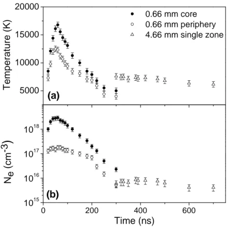
Spectra were recorded at different times and for two typical z-positions: one close to the laser impact (z1= 0.66 mm) and another near the substrate (z2= 4.66 mm). The same spectral analysis than above
was realized, and results were presented on figure 6(a) and (b). For the whole duration of the plasma at z1-position, the panache has a behaviour well simulated by a plasma composed by two uniform zones.
Electronic temperatures of both zones have the same time profile, with a maximum down-shift of about 4000 K for the periphery. The electronic density distribution presents the same behaviour with a maximum down-shift of about one decade for the periphery.
On figure 6, the time decrease of core temperature and density is about 10000 K and two decades respectively. This decrease from maximum values at 100 ns and ending at 300 ns corresponds to strong 1D expansion of the panache during the early times of plasma propagation.
At z2-position, 3D panache expansion had occurred, and it can be considered as uniform, and
simulation can be performed by a single zone. As it can be seen on table 4, temperature and density decrease slowly and maintain an important ionization rate in a large volume.
5000 10000 15000 20000
(b)
T
e
m
p
e
ra
tu
re
(K
)
0.66 mm core 0.66 mm periphery 4.66 mm single zone(a)
0 200 400 600 1015 1016 1017 1018N
e
(
c
m
-3
)
Time (ns)
Figure 6. Time dependences of plasma temperature (a) and electronic density (b), for two z-positions: for a
two-zones plasma z1= 0.66 mm and a one-zone plasma z2= 4.66 mm.∆t = 10 ns for t < 500 ns, and∆t = 100 ns for t > 500 ns. Under 30 Pa O2background pressure with a fluence of 2 J cm-2.
Temperatures and electronic densities estimated from this model are in good agreement with values from the literature obtained with other simulation approaches applied to similar experimental conditions [5,9,16-18]
.
4.2. Trace element detection
Pollution of targets may have different origins, either during their preparation, or during the polishing phase. Another source of plasma pollution may results from presence of old layers deposited on ablation chamber surfaces.
With this diagnostic we have validated the good stoechiometry of our targets. In addition some atomic emissions corresponding to pollutant species were also observed. For instance it was possible to quantify calcium and sodium elements from Ca II lines in BSTO targets and Na I lines in CCTO targets. Those elements directly came from the target and are introduced in the bulk, without control, during synthesis process, and none from inner chamber pollution. Indeed, they are detected even for long time ablated target and, at any time and in the whole plume.
In order to improve the pollutant concentration estimation, it was necessary to chose emission lines with significant emission probability coefficients. In that case it is possible to observe them even if they are in trace amounts. Considered transitions were grouped in table 5. Moreover high z-positions and long times are preferred so as to consider only one uniform plasma zone and therefore minimize the number of adjustable parameters. Firstly, we have only considered elements of a non-polluted target for the adjustment of synthetic spectrum on experimental one; secondly the concentration of pollutant species was adjusted to fit correctly these emissions. Simulations of spectra with those lines are fast and show a good accuracy in element concentrations. Two examples are shown on Figure 7
and figure 8 for calcium in BSTO and sodium in CCTO targets respectively. For these samples, we have found relative concentrations of about 28 ppm in mass and 0.26% in mass for calcium and sodium respectively.
Table 5. Atomic data [19] of Ca II and Na I lines.
λ0(nm) Aul(s-1) El(cm-1) Eu(cm-1) Config. Lower Config. Upper Term Lower Term Upper Jl Ju gl gu Ca II 393.366 1.47x10⁸ 0 - 25 414.40 3p64s - 3p64p 2S - 2P° 1/2 - 3/2 2 - 4 Ca II 396.847 1.4x10⁸ 0 - 25 191.51 3p64s - 3p64p 2S - 2P° 1/2 - 1/2 2 - 2 Na I 588.995 6.16x10⁷ 0 - 16 973.368 2p63s - 2p63p 2S - 2P° 1/2 - 3/2 2 - 4 Na I 589.592 6.14x10⁷ 0 - 16 956.172 2p63s - 2p63p 2S - 2P° 1/2 - 1/2 2 - 2 In our plasma conditions, depending essentially on Teand Ne, we can reach quantification thresholds of 10 ppm in mass and 50 ppm in mass for calcium and sodium respectively. In a general way, to increase the signal to noise ratio, the z-position will be adjusted: at high z-position for atomic lines and at moderate z-position for ionic lines.
0 2x10¹² 4x10¹² 393 394 395 396 397 398 0 2x10¹² 4x10¹² T i II C a II B a I B a I S r I T i I T i I T i I T i I T i I C a II S r I T i I
S
p
e
c
tr
a
l
ra
d
ia
n
c
e
(W
m
-3s
r
-1)
(a) ExperimentWavelength (nm)
(b) SimulationFigure 7. (a) experimental and (b) simulated spectra with Ca II trace in plasma from ablated BSTO target. Under
20 Pa O2background pressure with a fluence of 2 J cm-2, t = 400 ns, and∆t = 100 ns, z-position = 5.4 mm with a
spectral resolution of FWHM = 20 pm.
Table 6. Plasma parameters of figure 7(b) simulation spectrum, under uniform plasma.
T (K) 7000 Ne(cm-3) 9x10¹⁴ Thickness (mm) 16 Ba (mass %) 38.59 Sr (mass %) 16.45 Ti (mass %) 22.45 O (mass %) 22.5 Ca (mass ppm) 28
0 1x10¹¹ 2x10¹¹ 3x10¹¹ 4x10¹¹ 585 586 587 588 589 590 591 592 593 0 1x10¹¹ 2x10¹¹ 3x10¹¹ C a I T i I T i I T i I T i I N a I N a I T i I T i I T i I T i I T i I
S
p
e
c
tr
a
l
ra
d
ia
n
c
e
(W
m
-3s
r
-1)
(a) ExperimentWavelength (nm)
(b) SimulationFigure 8. (a) experimental and (b) simulated spectra with Na I trace in plasma from ablated CCTO target. Under
20 Pa O2background pressure with a fluence of 2 J cm-2, long time integration: t = 0,∆t = 1 µs, z-position = 8.3 mm with a spectral resolution of FWHM = 40 pm.
Table 7. Plasma parameters of figure 8(b) simulation spectrum, under uniform plasma.
T (K) 5800 Ne(cm -3 ) 2x10¹⁴ Thickness (mm) 20 Ca (mass %) 6.5 Cu (mass %) 31 Ti (mass %) 30.9 O (mass %) 31.3 Na (mass %) 0.26 5. Conclusion
We have performed diagnostics of a plasma produced by pulsed laser ablation of CCTO and BSTO oxides in low pressure oxygen atmospheres by comparing the emission spectra to the spectral radiance computed for a plasma in local thermal equilibrium. To take into account the spatial gradients of temperature and density, the plasma was divided into two uniform zones representing the plasma core and the peripheral zone, respectively. The analyses allowed us to distinguish between three characteristic stages of plume expansion after ablation of either CCTO or BSTO samples. For first times after the laser impact (t < 300 ns), we observe a 1D expansion of the plume with strong gradients of density and temperature, which is well simulated by a model based on two plasma zones. For longer times the expansion is isotropic (3D), which is well simulated by a model considering only one uniform zone.
In addition, this model authorizes a quick identification and estimation of pollutant element densities present as trace inside targets with a good accuracy. While it is necessary to take into account the transition probability of the line of the element observed as pollutant, it is possible to quantify a few ppm of impurities. Here with a transition probability around 1×10⁸ s-1 for Ca II and around 6×10⁷ s-1 for Na I it was possible to quantify a least a few tens ppm
References
[1] H. Bartels, Z. Phys. 125, 597-603 (1948).
[2] R. D. Cowan and G. H. Dieke, Rev. Mod. Phys. 20, 418-455 (1948).
[3] I. S. Fishman, G. G. Il'in, and M. K. Salakhov, Spectrochimica Acta Part B: Atomic Spectroscopy 50, 947-959 (1995).
[4] T. Fujimoto, Plasma Spectroscopy (Oxford University Press, Oxford, 2004).
[5] J. Hermann, C. Boulmer-Leborgne, and D. Hong, J. Appl. Phys. 83, 691-696 (1998).
[6] H. Zwiker, in Plasma Diagnostics, edited by W. Lochte-Holtgreven (John Willey and Sons, New York, 1968), p. 214-249.
[7] D. Karabourniotis, C. Karras, M. Drakakis, and J. J. Damelincourt, J. Appl. Phys. 53, 7259-7264 (1982).
[8] I. B. Gornushkin, N. Omenetto, B. W. Smith, and J. D. Winefordner, Applied Spectroscopy 58, 1023-1031 (2004).
[9] M. Ribiere, D. Karabourniotis, and B. G. Cheron, J. Appl. Phys. 105, 083309-7 (2009). [10] T. Sakka, T. Nakajima, and Y. H. Ogata, J. Appl. Phys. 92, 2296-2303 (2002).
[11] I. B. Gornushkin, C. L. Stevenson, B. W. Smith, N. Omenetto, and J. D. Winefordner, Spectrochimica Acta Part B: Atomic Spectroscopy 56, 1769-1785 (2001).
[12] J. Hermann and C. Dutouquet, J. Appl. Phys. 91, 10188-10193 (2002).
[13] J. Gonzalo, C. N. Afonso, and I. Madariaga, J. Appl. Phys. 81, 951-955 (1997).
[14] A. Klini, A. Manousaki, D. Anglos, and C. Fotakis, J. Appl. Phys. 98, 123301-8 (2005). [15] M. S. Dimitrijevic and S. Sahal-Bréchot, J. Quant. Spectrosc. Radiat. Transfer 49, 157-164
(1993).
[16] J. A. Aguilera and C. Aragón, Spectrochimica Acta part B 59, 1861-1876 (2004).
[17] F. J. Gordillo-Vazquez, A. Perea, J. A. Chaos, J. Gonzalo, and C. N. Afonso, Appl. Phys. Lett. 78, 7-9 (2001).
[18] S. S. Harilal, B. O'shay, and M. S. Tillack, J. Appl. Phys. 98 (2005).
[19] Y. Ralchenko, A. E. Kramida, J. Reader, and N. A. Team, (National Institute of Standards and Technology, Gaithersburg, MD, 2008).
Spectrum T1(K) T2(K) Ne1(cm-3) Ne2(cm-3) Thickness (mm) (a) 18000 12000 5x10¹⁸ 1x10¹⁷ L1 = L2 = 1 (b) 12000 8000 2x10¹⁷ 5x10¹⁶ L1 = L2 = 1
λ0 (nm) Aul (×106s-1) El (cm-1) Eu (cm-1) Config. Lower level Config. Upper level Term Lower level Term Upper level Jl Ju gl gu w [15] (nm) d [15] (nm) Ca II 393.366 147 0 25 414.400 3d24s2 3d2(3P)4s4p(3P0) a3F y5D0 1/2 3/2 2 4 0.019 -0.005 Ti I 393.424 0.45 386.874 25 797.600 3p64s 3p64p 2S 2P0 4 3 9 7 - -Ti I 394.778 9.6 170.132 25 493.722 3d24s2 3d2(1D)4s4p(3P0) a3F z3P0 3 2 7 5 - -Ti I 394.867 48.5 0 25 317.813 3d24s2 3d3(4F)4p a3F y3D0 2 1 5 3 - -Ti I 395.634 30 170.132 25 438.898 3d24s2 3d2(1D)4s4p(3P0) a3F y3D0 3 2 7 5 - -Ti I 395.821 40.5 386.874 25 643.695 3d24s2 3d2(3P)4s4p(3P0) a3F y3D0 4 3 9 7 - -Ti I 396.285 4.13 0 25 227.217 3d24s2 3d2(3F)4s4p(1P0) a3F y3F0 2 3 5 7 - -Ti I 396.427 3.09 170.132 25 388.334 3d24s2 3d2(3F)4s4p(1P0) a3F y3F0 3 4 7 9 - -Ca II 396.847 140 0 25 191.510 3p64s 3p64p 2S 2P0 1/2 1/2 2 2 0.016 -0.004
Zone T (K) Ne(cm-3) Thickness (mm) Pt(Pa) Pp(Pa) Ca I Ca II Cu I Cu II Ti I Ti II O I O II Core 13100 1.4×10¹⁸ 1 732288 2659 32916 32916 77046 14216 131485 434062 6005 Periph. 9400 1.4×10¹⁷ 0.45 61466 187 2868 4789 4438 1402 10888 36857 26
T (K) Ne(cm-3) Thickness (mm) Pt(Pa) Pp(Pa) Ca I Ca II Cu I Cu II Ti I Ti II O I O II 7200 8.0×10¹⁵ 3.7 2798 5 134 266 153 56 504 1680 0.1
λ0(nm) Aul(s-1) El(cm-1) Eu(cm-1) Config. Lower Config. Upper Term Lower Term Upper Jl Ju gl gu Ca II 393.366 1.47x10⁸ 0 - 25 414.40 3p64s - 3p64p 2S - 2P° 1/2 - 3/2 2 - 4 Ca II 396.847 1.4x10⁸ 0 - 25 191.51 3p64s - 3p64p 2S - 2P° 1/2 - 1/2 2 - 2 Na I 588.995 6.16x10⁷ 0 - 16 973.368 2p63s - 2p63p 2S - 2P° 1/2 - 3/2 2 - 4 Na I 589.592 6.14x10⁷ 0 - 16 956.172 2p63s - 2p63p 2S - 2P° 1/2 - 1/2 2 - 2
T (K) 7000 Ne(cm-3) 9x10¹⁴ Thickness (mm) 16 Ba (mass %) 38.59 Sr (mass %) 16.45 Ti (mass %) 22.45 O (mass %) 22.5 Ca (mass ppm) 28
T (K) 5800 Ne(cm-3) 2x10¹⁴ Thickness (mm) 20 Ca (mass %) 6.5 Cu (mass %) 31 Ti (mass %) 30.9 O (mass %) 31.3 Na (mass %) 0.26