Dynamic Channel Assignment in IEEE 802.11g
Mohammed Boulmalf Tarik Aouam Hamid Harroud
School of Science & Engineering School of Business Administration School of Science & Engineering Al Akhawayn University in Ifrane Al Akhawayn University in Ifrane Al Akhawayn University in Ifrane
Ifrane, Morocco Ifrane, Morocco Ifrane, Morocco
[email protected] [email protected] [email protected]
Abstract—In this paper, we propose a dynamic channel-assignment algorithm which minimizes the total interferences between Access Points (APs) of a Wireless Local Area Network (WLAN), while maintaining the Signal to Interferences Ratio (SIR) bigger than a certain threshold for all users. The algorithm initializes the channel assignment at the APs, and calculates the SIR for each user using Integer Linear Programming “ILP” for an open area and for an area with obstacles (walls). The proposed algorithm shows results with significant enhancement of the SIR over WLANs, and therefore an improvement of the throughput. The algorithm can be applied to any WLAN, irrespective of the user distribution and user load.
Keywords-component; WLANs; ILP; SIR;
I. INTRODUCTION
Mobile communication facilities have become commonplace in many aspects of everyday life. Wireless networks utilize radio waves and/or microwaves to maintain communication channels between computers. Wireless technology keeps improving and the cost of wireless products keeps decreasing. Popular wireless local area networking products conform to the IEEE 802.11 ‘Wi-Fi’ standards [1]. All wireless communication is based upon the application of a radio operating on an assigned frequency. Advantages of wireless include mobility and elimination of unsightly cables. The main disadvantage of wireless technologies resides in high potential for radio interference due to weather, other wireless devices, or obstructions like walls. The transmission characteristics of a radio wave and its attenuation in a particular environment depend upon its operating frequency, the distance between the transmitter and the receivers and various obstructing obstacles. The frequency assignment and interferences have been extensively investigated by researchers [2, 3, 4]. The authors in [2] noted that in general APs and channel assignment are always installed sequentially. Thus, they proposed a model that addresses both APs and channels as being the same. They proved that, by combining AP placement and channel, results are
better. The model presented in [3] is a dynamic channel assignment ILP that minimizes channel interference between neighboring APs with taking an AP as a reference. The authors in [4] investigated a weighted variant of the coloring graph algorithm to improve the utilization of the spectrum in IEEE802.11. They emphasized that a least congested channel assignment is not efficient with the continued growth of WLAN. However, the more a channel is congested, the more the throughput decreases.
In this research, we extend the work presented in [5] by proposing a mathematical model to assign channels to APs based on minimizing the total interferences between APs, while maintaining SIR bigger then a certain threshold ȕ. The algorithm takes into account the presence of different types of obstacles (i.e. walls). Minimizing the total interferences between APs by assigning them adequate frequencies will lead to a better throughput over the Network. Indeed, as shown in our previous work [6], the SIR is directly proportional to the network throughput.
The rest of this paper is organized as follow: The channel interferences are discussed in Section 2. In section 3, we define our mathematical model. In section 4, we analyze and explain the results obtained from three different scenarios. We conclude the paper in Section 5.
II. CHANNEL INTERFERENCE IN IEEE 802.11 A. The IEEE 802.11g Standard
The IEEE 802.11g is the latest wireless standard to be ratified by IEEE for WLANs. IEEE 802.11g is an extension to IEEE 802.11b which is the basis of the majority of WLANs existing today. IEEE 802.11g broadens IEEE 802.11b's data rates to 54 Mbps within the 2.4 GHz band using OFDM (Orthogonal Frequency Division Multiplexing) technology. To design and/or deploy a WLAN, an accurate deployment procedure is required to ensure sufficient coverage and network functionality (capacity,
interference, etc.). While wireless networking gear is often classified according to its standards-based signaling rate, such as 54 Mbps for IEEE 802.11g, the actual data throughput, or data being transmitted, is often just a fraction of the signaling rate’s theoretical maximum. Research conducted in [7] showed that the user throughput performance changes radically when access points or clients are located near an interfering transmitter or when frequency planning is not carefully conducted. Data throughput can also be limited due to a number of important environmental and product-specific factors including: (1) Distance between WLAN devices: APs and network interface cards (NICs), (2) Transmission power levels, (3) Effect of waveguide, e.g. in hallways, (4) Building and home materials, (5) Radio frequency interference, (6) Signal propagation, and (7) Antenna type and location. Therefore, even though the new 802.11g available products are capable of 54 Mbps signaling rate, the practical or “actual” data throughput is more likely to be much less than that (in the range of 10 – 12 Mbps). By experimental results, we showed in a previous work [8] that the co-channel interference clearly degrades drastically the TCP throughput (from 9Mbps to 2 Mbps) and UDP throughput from 9.7 Mbps to 8.6 Mbps. TCP suffering more than UDP due to the delays incurred by the retransmission and error detection. The throughput in UDP mode also decreases, but smoothly with co-channel interferences because there are no error detection and no retransmission
B. Channel overlapping in IEEE 802.11g
There are 14 channels in IEEE 802.11g. As depicted in Figure 1, channels 1, 6, and 11 are non-overlapping, but channel 1 which takes a bandwidth from 2.412 GHz to 2.435 GHz, overlaps with channels from 2 to 5. Each channel requires 30 MHz of bandwidth. This bandwidth is therefore shared with other access points operating in those overlapping channels.
Figure 1. Channels for IEEE 802.11g [9]
The frequency center of two frequencies of two adjacent channels is only separated by 5 MHz. The coefficient of overlapping is given by the following formula: (0,1 ) c f f Max − j− k (1)
Where fjis the channel assigned to APjfk is the channel affected to APk and c is the non overlapping portion of
two adjacent channels. It is approximately equal to 5. III. THE PROPOSED MODEL
A new channel assignment algorithm has been proposed. The channels are assigned to APs in such a way to minimize the interferences between APs, to maximize the SIRs for users, and guarantee SIRs always superior to a certain threshold ȕ. The obstacles (walls) are introduced in the formulation as an attenuation of the received power. Each type of obstacles has its proper attenuation taken from the work presented in [10]. The users are distributed uniformly and are connected to the AP from which they receive the maximum power.
A. Problem formulations
The propagation model used in this section is the following [11]: γ ) ( Pr 0 d d PK = (1)
Where Pr is the received power, P is the transmitted power, d is the propagation model path length, d0 is a
reference distance for antenna far-field, usually taken so that the normalization constant K equals 1. The path loss exponent Ȗ is usually between 2 and 6 for most indoor and outdoor environments and Į is the degree of conflict given by the following formula:
{
0,1,2,3,4,5}
) 1 , 0 max( 5 − − → ∈ = α α c f fj k (2) ° ¯ ° ® s frequencie g f APs k j users i : , : , : Decision variables: ¯ ® = otherwise f assigned is APj if Yjf 0 1 ° ¯ ° ® = otherwise conflict of ree a have AP and AP if W k j k j 0 deg 1 , , α αObjective function:
¦ ¦
»» ¼ º « « ¬ ª ≠ − − − j k j jk jk k d W P α α α , ) 5 ( 2 ) ( min (3) Subject to: ° ¯ ° ® ∀ °¿ ° ¾ ½ °¯ ° ® + » ¼ º « ¬ ª ≥ ¦ ≠ − − − − APj to assigned is i that such j i W d P d P i k j jk ik k ij j ) , ( . 2 (5 ) 2 β η α α (4)¦
= f jf forevery j Y 1 (5) ) 1 , 0 max( 5 , , , 1 c g f that such k g j f W Y Yjf kg jk − − = ∀ + ≤ + α α (6) binary W Y k j W jk jf jk : , , 1 α α α ∀ =¦
(7)Equation (1) is the objective function which minimizes the total interferences while considering the degree of conflict between channels (represented by Į) and the distance dij between the user i and the assigned APj. In
equation (4), Pj represents the power transmitted by APj
to user i. Equation (5) specifies that only one frequency is assigned to each AP. The constraint represented by equation (6) indicates that if a frequency f is assigned to APj and a frequency g is assigned to APk, then WjkĮ
is forced to be 1 for Į,otherwise WjkĮwill have 0 by
optimality.
IV. NUMERICAL ANALYSIS
A. Scenario 1
Figure 2 shows the distribution of 8 APs with a service area of 100 m x 70 m and 80 users uniformly distributed.
Figure 2. Scenario 1 with 8 APs
The transmitted power at each AP was set to 20 dBm (100 mW). The threshold ȕ is set to 10 dB. The simulation results for this scenario are depicted in Table 1:
TABLE I. RESULTS FOR SCENARIO 1
Access Point coordinates (x, y)
x and y are in meter Channel
AP1 (0, 0) 6 AP2 (100, 0) 6 AP3 (70, 0) 1 AP4 (100, 70) 1 AP5 (20, 30) 11 AP 6 (40, 50) 6 AP7 (65, 15) 1 AP8 (80, 70) 11
There is no overlapping between all the channels and the average SIR per user was found equal to 28.8 dB. The solution is optimal.
B. Scenario 2
Figure 3 depicts the position of 9 APs distributed in different location with their respective channels.
Figure 3. Scenario 2 with 9 APs
Table 2 shows an excellent distribution of channels without overlaps. The simulated average SIR per user is 39 dB. The total number of users was set to 90 users.
TABLE II. RESULTS FOR SCENARIO 2
Access Point coordinates (x,y)
x and y are in meter Channel
AP1 (0, 0) 6 AP2 (10, 10) 1 AP3 (20, 0) 11 AP4 (30, 10) 6 AP5 (40, 0) 1 AP 6 (50, 10) 11 AP7 (60, 0) 6 AP8 (70, 10) 1 AP9(80, 0) 11
C. Scenario 3
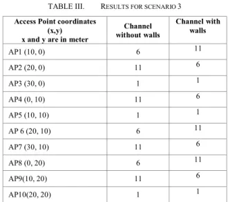
In this scenario we compare the performance of a configuration with 10 APs without walls and the same configuration with walls (obstacles). Table 3 shows the results of the channel assignment performed by our algorithm. Both with and without walls, the algorithm gives excellent results. All channels are none overlapping and there are no interferences between adjacent APs. The SIR was found equal to 47.5 dB for the configuration without walls and equal to 49 dB with walls which is normal because we have less interference in this configuration. The position of the vertical wall is x=15 and the horizontal wall is y=15.
TABLE III. RESULTS FOR SCENARIO 3
Access Point coordinates (x,y) x and y are in meter
Channel without walls Channel with walls AP1 (10, 0) 6 11 AP2 (20, 0) 11 6 AP3 (30, 0) 1 1 AP4 (0, 10) 11 6 AP5 (10, 10) 1 1 AP 6 (20, 10) 6 11 AP7 (30, 10) 11 6 AP8 (0, 20) 6 11 AP9(10, 20) 11 6 AP10(20, 20) 1 1 D. Scenario 4
The objective of this scenario is to compare the performance of two congested networks with and without walls. 100 users were distributed by the algorithm uniformly per APs. Table 4 shows the position of each AP and its corresponding channel. The average SIR per user was found equal to 42 dB without obstacles and 43.5 dB with obstacles.
TABLE IV. RESULTS FOR SCENARIO 4
Access Point coordinates (x,y) x and y are in meter
Channel
without Walls Channel with walls AP1 (0, 0) 6 1 AP2 (10, 10) 1 6 AP3 (20, 0) 11 11 AP4 (30, 10) 6 1 AP5 (40, 0) 1 11 AP 6 (50, 10) 6 6 AP7 (0, 20) 11 11
Access Point coordinates (x,y) x and y are in meter
Channel
without Walls Channel with walls AP8 (40,20) 11 11 AP9(10, 30) 6 1 AP10(30, 30) 1 6 AP11(0, 40) 1 6 AP12(20, 40) 11 11 AP13(40, 40) 6 1
The vertical wall was placed at x=25 m and the horizontal wall at y=15 m, which means there are 4 quadrants. Quadrant 1 contains AP1, AP2 and AP3. Quadrant 2 contains AP4, AP5 and AP6. Quadrant 3 contains AP7, AP9, AP11, and AP12. Finally quadrant 4 contains AP8, AP10, and AP13. AP7 and AP8 are assigned the same channels because they are far from each other, and they belong to two different quadrants, so the interference is minimal.
E. Scenario 5
The objective of this scenario is to determine the assignment of frequencies while having one AP with a pre-configured channel. We selected AP10 (30, 30) and we fixed its channel to 2. 100 users were distributed by the algorithm uniformly per APs. Table 5 shows the position of each AP and its corresponding channel. The algorithm provides the optimal solution by selecting the frequencies 2 and 7 only. There are non overlapping channels.
TABLE V. RESULTS FOR SCENARIO 5
Access Point coordinates (x,y) x and y are in meter
Channel without Walls AP1 (0, 0) 7 AP2 (10, 10) 2 AP3 (20, 0) 7 AP4 (30, 10) 2 AP5 (40, 0) 7 AP 6 (50, 10) 2 AP7 (0, 20) 7 AP8 (40,20) 7 AP9(10, 30) 2 AP10(30, 30) 2 AP11(0, 40) 7 AP12(20, 40) 7 AP13(40, 40) 7
V. CONCLUSION
A channel assignment algorithm has been proposed based on minimizing the total interferences between APs, while maintaining a good QoS. We achieve a good QoS by insuring that the Signal to Interferences Ratio (SIR) for each user is greater than an acceptable threshold. We formulated the problem using ILP (Integer Linear Programming) for an open area and an area with obstacles (walls). Users are distributed uniformly by the algorithm. The results obtained showed an optimal solution which means that the channels are distributed over APs with a minimum of interferences. The algorithm has shown to provide superior results to previous research work that did not take into account obstacles and SIRs for users. The algorithm is fast for medium networks (8 APs to 15 APs) where the solution time is about 2 to 5 minutes. For large networks the size of the problem grows exponentienly up to few hours. There is, therefore, a need for the decomposition method for solving large ILP problems. We are currently investigating the load balancing for users in terms of their throughput (not their assignment to the APs), and we will also investigate how we should assign users to APs while taking into account assigned channels to APs.
REFERENCES
[1] IEEE 802.11 Standards (1999) Wireless LAN Medium Access Control and Physical Layer Specification, Working Group, http://www.ieee.org/groups/802/11.
[2] Eisenblätter, A., Geerdes, H.-F. and Siomina, I., “Integrated Access Point Placement and Channel Assignment for Wireless LANs in an Indoor Office Environment,” 8th IEEE Intl. Symposium on a World of Wireless, Mobile and Multimedia Networks, June 2007.
[3] R. Akl and A. Arepally, “Dynamic Channel Assignment in IEEE 802.11 Networks,” Proceedings of IEEE Portable 2007: International Conference on Portable Information Devices, March 2007
[4] R. Rodrigues, G. Mateus, A. Loureiro, "Optimal Base Station Placement and Fixed Channel Assignment Applied to Wireless Local Area Network Projects," Seventh IEEE International Conference on Networks (ICON'99), 1999, pp.186.
[5] M. Haidar, R. Ghimire, M. Al-Rizzo, R. Akl, Y. Chan, “Channel Assignment in an IEEE 802.11 WLAN Based on Signal-to-interference Ratio”, IEEE CCECE – Canadian Conference on Electrical and Computer Engineering: Communications and Networking, May 2008.
[6] M. Boulmalf, H. El-Sayed, and A. Soufyane, “Measured Throughput and SNR of IEEE 802.11 g in a Small Enterprise Environment,” 61st Vehicular IEEE Vehicular Technology Conference, Vol. 2, pp. 1333-1337, Stochholm, Sweden, June 2005.
[7] B. E. Henty, "Throughput Measurements and Empirical Prediction Models for IEEE 802.11b Wireless LAN (WLAN) Installations", Master thesis, Virginia Polytechnic Institute and State University, August 9, 2001,Virginia,USA.
[8] M. Boulmalf, T. Rabie, K. Shuaib, A. Lakas, H. El-Sayed , “Performance evaluation study of an indoor IEEE 802.11g” International Journal of Value Chain Management 2008 - Vol. 2, No.1 pp. 109
[9] http://www.draytek.co.uk/support/kb_vigor_wlanchannels.ht ml.
[10] M. Boulmalf and A. Lakas, "Semi-empirical Method for Simulating Wireless Indoor Attenuation," The International Journal of Advanced Media and Communication "IJAMC", 2006
[11] D. Julian, M. Chiang, D. O’Neill and S. Boyd,"QoS and fairness Constrained Convex Optimization of Resource Allocation for Wireless Cellular and Ad Hoc Neworks," The IEEE INFOCOM, 2002.
![Figure 1. Channels for IEEE 802.11g [9]](https://thumb-eu.123doks.com/thumbv2/123doknet/13102916.386144/2.918.129.405.766.941/figure-channels-for-ieee-g.webp)