HAL Id: cea-01851800
https://hal-cea.archives-ouvertes.fr/cea-01851800
Submitted on 30 Jul 2018
HAL is a multi-disciplinary open access
archive for the deposit and dissemination of
sci-entific research documents, whether they are
pub-lished or not. The documents may come from
teaching and research institutions in France or
abroad, or from public or private research centers.
L’archive ouverte pluridisciplinaire HAL, est
destinée au dépôt et à la diffusion de documents
scientifiques de niveau recherche, publiés ou non,
émanant des établissements d’enseignement et de
recherche français ou étrangers, des laboratoires
publics ou privés.
Study of thermal ageing effects on Rh coating’s
mechanical performance upon CuCrZr substrate
through modeling and experimental methods
Z.X. Chen, Julien Hillairet, V. Turq, Y.T. Song, R. Laloo, K. Vulliez, J.M.
Bernard, Q.X. Yang, C. Hernandez, L. Ferreira, et al.
To cite this version:
Z.X. Chen, Julien Hillairet, V. Turq, Y.T. Song, R. Laloo, et al.. Study of thermal ageing effects
on Rh coating’s mechanical performance upon CuCrZr substrate through modeling and experimental
methods. Vacuum, Elsevier, 2018, 154, pp.227 - 234. �10.1016/j.vacuum.2018.05.018�. �cea-01851800�
Contents lists available atScienceDirect
Vacuum
journal homepage:www.elsevier.com/locate/vacuum
Study of thermal ageing e
ffects on Rh coating's mechanical performance
upon CuCrZr substrate through modeling and experimental methods
Z.X. Chen
a,b,∗, J. Hillairet
a, V. Turq
b, Y.T. Song
c, R. Laloo
b, K. Vulliez
d, J.M. Bernard
a, Q.X. Yang
c,
C. Hernandez
a, L. Ferreira
e, F. Fesquet
eaCEA, IRFM, F-13108, Saint-Paul-Lez-Durance, France
bInstitut Carnot CIRIMAT, UMR CNRS-UPS-INP 5085, Université Paul-Sabatier, 118 Route de Narbonne, 31062, Toulouse Cedex 9, France cInstitute of Plasma Physics, CAS, Hefei, Anhui, 230031, China
dLaboratoire d’étanchéité, DEN/DTEC/SDTC, CEA, 2 Rue James Watt, 26700, Pierrelatte, France eCERN, Geneva, Switzerland
A R T I C L E I N F O Keywords: Rh coating CuCrZr Thermal stress Cracking Hardness Adhesion A B S T R A C T
Rhodium (Rh) coating on CuCrZr substrate is a promising material option for optical, structural and electrical applications on nuclear fusion reactors. For these applications, Rh coated CuCrZr components subject to long time of thermal ageing due to pre-treatment or normal operation condition. In this paper, bothfinite element method (FEM) and experimental method were applied to investigate the effects of thermal ageing on mechanical performance of Rh coating after 250 °C, 500 h baking in vacuum. Based on FEM analysis, thermal stresses which concentrate at Rh coating interface is the main source of cracking, and such stresses can be minimized efficiently by introducing a 0.5μm Au interlayer into the coating layer structure. According to thermal ageing experiments, through-thickness cracking in the Rh coating due to thermal stress releasing and voids generated at the Rh bonding interface caused by Kirkendall effect were the main micro-structure changes in the coating system. The solid-solution hardening caused by significant Cu diffusion into Rh is the dominant factor that affected the Rh coating's hardness. The existing of large amount of cracks in the Rh coating and voids at the Rh coating interface deteriorated the adhesion performance of Rh on CuCrZr substrate by 30%.
1. Introduction
Metallic rhodium provides the unique combination of excellent physical and chemical properties especially in electrical conductivity, hardness, optical reflectance and wear resistance. Due to its good properties, Rh has wide industrial applications on electronics, electrical contacts, optic equipment and medical implants as well [1]. As a noble metal, it is costly to use Rh as bulk material to manufacture products, and instead, depositing it as a functionalfilm on suitably selected base materials is a common industrial approach. Rh coatings are typically deposited by electroplating, physical vapor deposition, or chemical vapor deposition techniques [2].
Rh deposition by magnetron sputtering was explored and studied for the application as a coating material candidate for the International Thermonuclear Experimental Reactor (ITER) first mirror diagnostic, which sustains repetitive thermal stress load [3–7]. In these studies, the attempt of applying Rh thin coating (200 nm) on stainless steel 304 L, molybdenum and Cu was performed and their failure mechanisms were investigated. According to the results, Rh on 304 L showed much better
coating attachment performance than on Cu. And from the micro-scratch tests, the critical load of Rh on Cu is only about 1/4 of the critical load of Rh on 304 L. Compared with stainless steel, Cu and Cu alloys have much better thermal and electrical properties which are appropriate to be used on electrical or thermal handling applications such as electrical contact. In addition, Rh coating can be plated as protective coating which prevents its substrates from wear. On the Large Hadron Collider (LHC) accelerator, Rh coatings on Cu and CuBe (C17410) were evaluated based on their electrical performance for sliding RF contact application [8–10]. On ITER tokamak, RF sliding contacts [11–13] are being developed on which Rh is expected to be electroplated on the CuCrZr substrate to improve its wear and corrosion resistance.
For fusion reactor applications, the Rh coatings being applied are working under high or ultrahigh vacuum [14,15], and long duration of high temperature baking around 250 °C (with a slow heating rate about 5 °C/h) is mandatory for outgassing [16,17]. Although Rh coatings' mechanical performance on different substrates were researched and introduced in other literature [3,5], the effects of 250 °C thermal ageing
https://doi.org/10.1016/j.vacuum.2018.05.018
Received 15 April 2018; Received in revised form 12 May 2018; Accepted 14 May 2018
∗Corresponding author. CEA, IRFM, F-13108, Saint-Paul-Lez-Durance, France.
E-mail address:zhaoxi.chen@cea.fr(Z.X. Chen).
0042-207X/ © 2018 Elsevier Ltd. All rights reserved.
on the Rh coatings' properties and adhesion performance were not detailed studied, which is very important to evaluate the Rh coatings' life time used on such machines as wear protective coatings. The pur-poses of this paper are to investigate the thermal ageing effects on the Rh electroplating upon CuCrZr substrate by using finite element method (FEM) as well as experimental method, and to understand the mechanisms of crack generation, hardness transition and adhesion strength variation caused by thermal ageing process.
2. Coating design and thermal stress modeling
The mechanical integrity of a coating material depends on the re-sidual stresses which come from four principal sources: growth stresses during coating formation, geometric constrains, service stresses and thermal stresses [18]. Thermal stresses are induced during the baking and cooling periods by the uniform temperature distribution of the structure and the thermal expansion mismatch between the coating and the substrate [19,20]. Considering the relative small thickness of the Rh coating to the massive CuCrZr substrate and the low temperature transition rates during heating and cooling processes, at every moment the temperature on the components can be regarded as steady-state, and there is no significant temperature gradient exists between Rh coating and its substrate. Thus, the difference of coefficient of thermal expansion (CTE) between materials is the major source of thermal stresses. Unlike functional Rh coatings used for optical applications, to be used as wear resisting coatings, larger thickness is required. The increase of the coating thickness can decrease the bonding strength and increase the residual stress [21]. Therefore, for thick Rh coatings, thermal stresses should be evaluated carefully.
Instead of depositing the coating materials directly on the sub-strates, applying interlayers can obviously reduce the residual stresses by reducing the mismatch of CTE between coating and its substrate [22]. In addition, for rigid coating and substrate, applying of a relative soft interlayer can relax thermal stresses through phenomena of ductile, creep and plasticity [23]. For the electroplating point of view, non-precious metals can be properly plated only after pre-plating of Ni or Au interlayer to avoid the substrate corrosion in the high acidity of Rh electrolyte [1], and the good adhesion of Rh on Au had been approved [24]. As shown inTable 1, Au is a suitable interlayer coating candidate to improve the thermal stresses in the Rh coating.
2.1. Analysis model and boundary conditions
Numerical simulation of the thermal stresses generated in the Rh coating during baking period (heating-up and cooling) and the effects of introducing Au interlayer were simulated by using ANSYS FEM code. The thickness of the Rh coating wasfixed as 3 μm and the interlayer of Au was modeled as 0.5μm. The case without interlayer can be simu-lated by changing the interlayer material from Au to CuCrZr. Although the thickness of the CuCrZr substrate was defined as 20 μm, the sub-strate is thick enough in comparison to the coating layers to reveal the true mechanical behaviors. Transversal cross-section of the coatings was modeled in a 2-D approach as shown inFig. 1. There are several assumptions in the finite element (FE) analysis model: the model is assumed to be perfect elastic bodies without plastic deformation oc-curring; the coating interfaces are perfect bonding with low thermal
contact resistance; the temperature on the whole model is uniform without temperature gradient existing and the whole model was stress free after electroplating at room temperature (i.e., 25 °C).
In order to improve analysis precision, mapped meshing was used to generate full quadrilateral-shaped elements andfine mesh was applied on the two thin coatings to avoid high stress concentration. The dis-placement of the model's left edges was constrained in X direction and free in Y direction and the node located at the bottom left corner was fixed without any movements permitted. Thermal loads were applied on the model by setting the reference temperature as 25 °C and body uniform temperature from 25 °C to 250 °C to mimic the heating-up period (the same stresses results as cooling period from 250 °C to 25 °C). 2.2. Von-Mises stress analysis result
Static structural analyses were performed and the maximum Von-Mises stresses on the model under different temperature loads as well as with or without Au interlayer were plotted inFig. 2 (a). The maximum thermal stress is almost linearly increased with the increase of the baking temperature. When baking temperature rises to its peak value of 250 °C, the maximum thermal stress in the Rh layer without Au inter-layer is about 333 MPa and this value can be reduced significantly by 44 MPa if a 0.5μm Au interlayer applied. FromFig.2(c) and (d), it can be seen that the peak stresses occurred at the corner and high tensile stress appears only in Rh layer near the bonding interface with Au or CuCrZr.Fig. 2 (b)shows the distribution of thermal stress through the thickness of the coating and substrate at the right edge. The stress distributions for the cases with and without Au interlayer are similar, and the tensile stress in the Rh coating increases with the depth increase and this stress turns to compressive stress in the Au and CuCrZr layers with a sudden value decrease. The yield stress of Rh was reported in Ref. [25], which showed that the yield stress of Rh at room temperature is 67 MPa. So, even though Au interlayer is applied, yield phenomenon of Rh layer especially at the coating interface would be inevitable. And large tensile stress in the Rh layer is prone to generate cracks. 2.3. Shear stress analysis result
The coating failure mechanism has a close relationship with the shear stress and the shear stress reveals the adhesion strength of the coating [26]. Spallation of the coating can occur if the shear stress at the bonding interface is higher than the bonding strength. The shear stress distribution of Rh coating at 250 °C along X-direction at different depth with and without Au interlayer was studied and the results are shown inFig. 3. As free surface, the shear stresses at the top surfaces are very low. Both for the Rh coatings with and without Au interlayer, when the depth getting deeper, the shear stress increases accordingly.
Table 1
Main material properties of Rh, CuCrZr and Au at room temperature. Property Material
Rh CuCrZr Au
CTE ( × 10−6/K) 8.2 16.7 14.2 Young's Modulus (GPa) 372 127.5 76.6 Poisson's Ratio 0.26 0.33 0.42
Fig. 1. FE modeling and boundary conditions.
Z.X. Chen et al. Vacuum 154 (2018) 227–234
There is a sharp increase of shear stress observed at the Rh bonding interface with CuCrZr, and the maximum shear stress reached to 141 MPa. The stress concentration at the edge area will be a source of cracks and delamination. If an Au interlayer is applied, a significant reduction of shear stress at the Rh bonding interface was observed by decreasing the maximum shear stress about 50 MPa. However, in other depths the effects of applying Au interlayer are not obvious.
2.4. Rh coating failure mechanism
As shown inFig. 4, after plating, there is no thermal stress existing, while during baking, due to the lower CTE of Rh compared with Au/ CuCrZr layers, Rh coating acts as constraint to other layers for thermal expansion and bending deformation occurs in the assembly. And as a result, tensile stress generated in the Rh coating. Based on the FE si-mulation, the maximum thermal stress occurs at the Rh bonding in-terface. When the thermal stress in the coating is higher than the coating's strength, cracking or fracture appears. Especially for the ma-terials which have low ductility in property such as Rh, their deposits are inherently brittle because they contain cracks that readily lead to fracture. The initial cracks in the Rh coating are unstable and they can be spread rapidly by accompanying of very little plastic deformation. The directions of crack generation are almost perpendicular to the di-rection of the applied tensile stress caused by the thermal stresses, which include the crack propagation tendencies to the top surface of the Rh coating and parallel to the coating surface. The fracture surfaces (along the thickness of the coating) of the cracks are relatively flat without obvious plastic deformation happened. With the cracks gen-eration and propagation, the thermal stresses in the coating assembly are released.
Based on the FEM simulation, the efficiency of applying Au inter-layer to decrease the thermal stress in the Rh coating was validated. The large tensile thermal stress induced in the Rh coating due to tempera-ture transition during baking would be a source of crack generation and propagation. However, for the Rh coating aiming to be applied on ac-celerator or nuclear fusion devices, beside the temperature rise or cooling period, long duration of baking at 250 °C is mandatory which can modify the Rh coating's crystal structure, mechanical properties and even chemical compositions. Such changes could alter the Rh coating's adhesion performance and influence its wear resistance. These
effects are hard to be predicted by other methods except for experi-mental characterizations. In order to have better understanding of the Rh coating's behavior under long duration of 250 °C baking, thermal ageing test towards coating samples of Rh on CuCrZr substrates was carried out.
3. Experimental methods 3.1. Materials and samples
Among all the Rh coating methods, electroplating is a proper technique for high quality Rh plating which has obvious advantages to achieve thick coatings on large size and complex geometry components. All the above advantages make electroplating to be a promising coating process for Rh coating application on large accelerator and fusion de-vices. In this study, electroplating was selected to prepare the samples. The substrates plates with sizes of 10 mm (length) × 8 mm (width) × 2 mm (thickness) and surface roughness (Sa) of 0.44μm were made of CuCrZr (C18150), whose chemical composition is shown in Table 2. The coating design was as discussed in the modeling section, which is 3μm thick Rh with a 0.5 μm thick Au interlayer.
3.2. Thermal ageing process
In order to mimic the baking process for high vacuum obtaining on accelerator and fusion devices, a group of coated samples went through thermal ageing at high temperature of 250 °C under 10−6Pa vacuum condition. These samples were heated from room temperature with the heating rate of 1.3 °C/min to 250 °C and then aged under 250 °C for 500 h, after that they were cooled down to room temperature by 0.16 °C/min.
3.3. Characterizations
The morphology of the samples was observed by scanning electron microscopy (SEM) coupled with energy-dispersive X-ray spectroscopy (EDS) using the JEOL JSM 6700 F electron microscope and the effects of high temperature thermal ageing and solid diffusion between different materials were studied.
Two views were selected to be observed: top surface observation to
Fig. 2. FE simulation results of Von-Mises stresses: (a). Results of maximum thermal stresses; (b). Thermal stress distribution through thickness at the right edge of the model; (c). Contour plot of thermal stress distribution under 250 °C without interlayer; (d). Contour plot of thermal stress distribution under 250 °C with Au interlayer.
check the coating quality as well as crack phenomenon; cross-sectional view to observe the crack depth and to evaluate the material intrusion between different layers due to diffusion. Image analyzing software Image J (US National Institute of Health) was applied to analysis the SEM images and to quantify the crack generation and propagation. The crystal structure including crystal phase, crystallite size, and lattice constants of different coatings was characterized by using an X-ray diffractometer (XRD, BRUKER D4 ENDEAVOR, Germany) with Ni filter
Cu Kα radiation (λ = 1.54184 Å, 40 kV, 40 mA). The X-ray diffraction data was collected from 10° to 100° in 2θ with a 0.0157° step scan. The micro-Vickers hardness of the coatings was measured by using a Vickers micro-hardometer (Model: HM-210, Mitutoyo, Japan), with test force from 10 gf to 1000 gf. At least six measurements were performed per sample to make statistical analysis. The coating's adhesion properties were evaluated by using a CSEM®commercial micro-scratch tester. The scratch indenter was a diamond stylus that has a Rockwell C geometry with a 120° cone and a 200μm radius spherical tip. A progressive load from 1 N to 50 N with a loading rate of 49 N/min was applied and the indenter transverse speed was 4 mm/min with a scratch length of 4 mm.
4. Results and discussion 4.1. Micro-crack
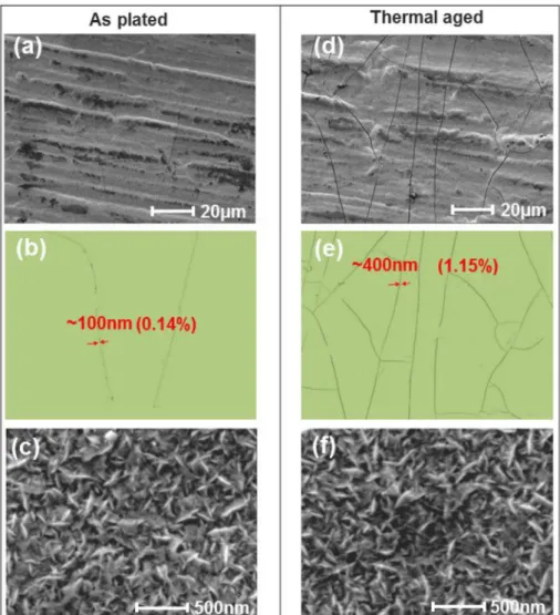
As shown inFig. 5, on the Rh coating's SEM view under magnifi-cation of × 1000, columnar ridges were observed on the surface of Rh coating and the coating is very dense without pores. Very few narrow cracks were observed, which were mainly induced by the chemically generated internal stresses which usually arise during the coating's fabrication process and highly correlated with the processing conditions [27–29]. Actually, one of the most serious disadvantages of electro-plating is the presence of high internal stresses that can lead to cracking in the coating [30]. In order to quantify the cracks, two parameters were used which include the crack spacing and crack area proportion. The crack spacing is defined as the parallel distance between crack edges to the coating substrate. The cracking susceptibility was eval-uated by the proportion of cracks area per surface area of coating which can be processed and calculated through Image J software. After thermal ageing, the number of cracks on the Rh coating increased sig-nificantly and the crack spacing enlarged. The area proportion of cracks increased from 0.14% to 1.15% with crack spacing increasing from 100 nm to 400 nm. Moreover, the cracks have obvious parallel dis-tribution characteristic. The explanation of crack generation and pro-pagation during thermal ageing treatment is the tensile thermal stresses' relaxation which is introduced in section2.4.
Under magnification of × 50000, the dense acicular grains, with averaged size of 200 nm in length and 50 nm in width were observed. After 250 °C, 500 h thermal ageing, the acicular morphology of the Rh coating was not changed and the average size of the acicular particles was similar with the initial coating. Thefine-grained deposit structure of Rh increased the tendency of crack generation since the plastic de-formation that occurs primarily by dislocation motion can be sig-nificantly impeded by the plenty of grain boundaries.
Fig. 3. FE simulation of shear stresses at 250 °C: (a). Shear stresses in the Rh coating along X direction without Au interlayer; (b). Shear stresses in the Rh coating along X direction with Au interlayer.
Fig. 4. Failure mechanism of the Rh coating during baking. Table 2
Chemical composition of CuCrZr (C18150).
Cu Cr Zr
Base 0.7 wt.% 0.04 wt.%
Z.X. Chen et al. Vacuum 154 (2018) 227–234
4.2. Metal diffusion
Diffusion is the movement of atoms through crystallite lattice which happens in any state of material above absolute zero, and baking can accelerate this process. By using diffusion phenomenon, tight material bonding can be realized under solid state [31,32]. However, at the binary solid interface, if the diffusion rates of the two materials are different, the number of vacancies will increase in the side where the faster diffusion atoms come from, and when the quantity of such va-cancies exceed its equilibrium concentration, pores will be formed due to the accumulation of the vacancies, which is referred as Kirkendall effect [33]. Such pores are very harmful for coating's adhesion strength. As Rh coatings are electrical functional coatings which will bear friction load, voids shall be avoided. During long time high temperature baking in vacuum, the diffusion phenomenon and its effect should not be ne-glected which may change the mechanical and electrical properties of the coatings or change the coatings' lifetime by impacting their adhe-sion that can induce more serious wear phenomena. In order to in-vestigate and evaluate the intermetallic diffusion behaviors, EDS line analyses along the coatings' thickness direction were performed to ob-tain the target elements' compositional profiles.
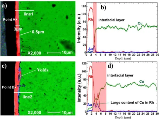
The EDS mapping of the Rh coating on CuCrZr substrate as plated is shown inFig. 6 (a). On this sample, the Rh layer and CuCrZr substrate had a clear coating interface without any pores observed, and about 0.5μm of Au interlayer was applied to improve electroplating perfor-mance of Rh on CuCrZr. The thickness of the Rh layer was about 3μm.
Fig. 6 (b) is the elements' depth profiles along line 1, good bonding interfaces can be proved by the abrupt changes of curves at the coating interfaces. AsFig. 6 (c)shows, after thermal ageing, serious diffusion happened at the Rh and CuCrZr interface and voids generated. The diffusion was both happened between Au/Cu and Rh/Cu. Because of the inhomogeneity of diffusion, Au interlayer disappeared in some areas and gathered in other regions. Due to the large amount of Cu that diffused into Rh layer and the voids' generation, at some positions the thickness of the Rh layer increased from 3μm to about 4 μm. The voids generated at the coating interface due to diffusion can degrade the at-tachment performance between Rh coating and Cu substrate. Conse-quently, the wear resistance of the Rh coating will be deteriorated. Based on the profiles of the coatings (Fig. 6 (d)), the thickness increase of the Rh layer and Au layer was observed, and serious diffusion of Cu into Rh was proved. The Cu atoms that diffused into Rh layer were also increased the solid solubility of Au in the Rh layer.
In order to quantify the Cu diffusion into Rh, EDS point analyses were performed and the diffusion phenomenon was studied through analyzing the chemical compositions of the Rh coatings. As Fig. 7 shows, before thermal ageing, the compositions in the Rh coating are: Cu-2.67 wt. %, Rh-97.33 wt. %. However, after thermal ageing, the Cu content increased significantly to 12.89 wt. %.
4.3. Crystal structure
Crystallite sizes of the coatings and phase transition are closely
Fig. 5. Surface morphology of the Rh coating on CuCrZr substrate: (a, d). SEM images of original coating and thermal aged coating ( × 1000); (b, e). Cracks on the original coating and thermal aged coating processed by Image J; (c, f). SEM images of original coating and thermal aged coating ( × 50,000).
related with the coatings' mechanical properties like hardness which would affect their wear performance. This information can be studied from the XRD patterns by observing the peaks positions as well as their full-width at half-maximum (FWHM). The crystallite size of the coating can be calculated by using Scherrer equation [34].
The crystallite size of the Rh coating before thermal aging is about 7.5 nm, with lattice constant of 0.3787 nm. Cu (Cu alloy) peaks were observed in the pattern due to the X-ray penetration to the base ma-terial of the Rh coating (Fig. 8). Compared with initial sample, after
thermal aging, the phenomenon of the Rh pattern peaks shifting to high θ direction weakened, which was caused by the diffusion of Au layer into the Rh layer (after thermal ageing, the content of Cu in Rh in-creased significantly which raised the solid solubility of Au in Rh). The melting point of Rh is 1966 °C, so 500 h thermal aging at 250 °C would not influence the crystallite size of the Rh coating too much. The crystallite size grows to 11.3 nm during thermal aging with lattice constant about 0.3802 nm. No Au peaks found from the XRD pattern which means that the thin Au layer had been diffused into Cu base and no Au or Au-based alloy existed.
4.4. Hardness
The hardness of a material is one of the most important mechanical properties that can be used to evaluate the material's abrasive wear resistance [35]. Generally, the abrasive wear resistance of materials is
Fig. 6. Mapping and depth profile of the Rh coating on CuCrZr substrate: (a). EDS mapping of original sample section; (b). Elements profiles along line1; (c). EDS mapping of thermal aged sample section; (d). Elements profiles along line2.
Fig. 7. EDS point analyses of Rh coatings inFig. 6 (a). EDS spectrum of point A; (b). EDS spectrum of point B.
Fig. 8. XRD patterns of Rh coatings on CuCrZr substrates (original and thermal aged).
Z.X. Chen et al. Vacuum 154 (2018) 227–234
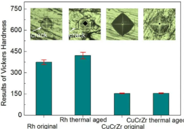
linearly proportional to their hardness. The reason that Rh is widely selected as the wear protective coatings is due to its extremely high hardness characteristic. In section 4.2 and section 4.3 the thermal ageing effects to the Rh coating were investigated through the char-acterizations of material diffusion and crystal structure modification. Large content of Cu diffused into Rh layer was observed and the crys-tallite size increase of Rh was validated. There are two factors that affected the hardness of the Rh coating after thermal ageing which include crystallite coarsening that could decrease the Rh coating's hardness and the solid-solution hardening effect due to Rh-Cu inter-diffusion that could increase the Rh coating's hardness.
In order to evaluate the thermal ageing effect on the Rh coating's hardness, microhardness measurements were carried out and the results (HV0.02) are summarized inFig. 9. The hardness of the Rh coating after thermal ageing is 421.8 ± 22.3 which is obviously higher than the hardness (375.5 ± 16.4) of the original Rh coating. Cracks were ob-served around the impressions both on the original and thermal aged Rh coatings, which were mainly caused by the large gap of hardness between Rh and CuCrZr. The hardness of CuCrZr substrates before and after thermal ageing was measured, and their hardness was around 154 without change. Therefore, based on these results, the hardness in-crease after thermal ageing indicates that the solid-solution hardening effect of Cu diffused into Rh crystal lattice was the dominant factor to
affect the hardness of the Rh coating. 4.5. Adhesion performance
Adhesion performance of coating reveals its wear resistance. And in order to evaluate Rh coatings' adhesion performance, scratch tests were performed and the results are shown inFig. 10. The critical loads of Rh coatings were determined by microscopic observation of scratch tracks and assisted by the variation of acoustic emission as well as coefficient of friction (CoF) signals. The failure of Rh coating on CuCrZr substrate during scratch tests presents a typical mechanical behavior of a hard and brittle coatingfilm deposited on soft substrate, whose main failure phenomenon is coating cracking through the whole thickness.
For the original Rh coating on CuCrZr, with the increase of the test load, angular cracking occurred and then tensile cracking was observed. At around 13 N, obvious transitions on the signals of acoustic emission and CoF happened. And based on SEM observation, the dense tensile cracks turned to massive Rh delamination at that time. So, the critical load of original coating on CuCrZr substrate was characterized as 13 N. However, for the samples that baked at 250 °C for 500 h, there was no obvious transition points on the acoustic emission and CoF curves. Through SEM microscopic observations, on the scratch track, there are no regular cracks generated. Mesh cracking generated at the beginning of the scratch test and Rh peeling was observed at about 9 N. The de-generation of the Rh coating's adhesion performance is caused by two reasons: the cracks generated during thermal ageing and the large quantity of holes exiting at coating interface due to Kirkendall effect. The exiting of holes and original cracks impairs the supporting of the base material (CuCrZr) to the Rh coating, therefore, cracks generated faster without any direction of orientation and peeling happened ear-lier.
5. Conclusion
In this work, thermal ageing effects (250 °C, 500 h) on Rh which is used as wear protection coating upon CuCrZr substrate is evaluated through FEM and experimental methods. The mechanism of crack generation, hardness transition, bonding interface variation and coating adhesion strength degradation were investigated. The conclusions of the present work are summarized as follows:
Fig. 9. Measurement of Vickers hardness of Rh coating and CuCrZr substrate.
Fig. 10. Scratch tests results of Rh coating on CuCrZr substrates: (a, d). Acoustic emission and CoF signals of original and thermal aged samples; (b, e). Optical mi-croscope images of scratch tracks of original and thermal aged samples; (c, f). SEM mi-crographs of cracks on the scratch tracks of original and thermal aged samples.
(1) Through FE analysis, large thermal stresses generated due to the mismatch of CTE between Rh and CuCrZr at the Rh coating inter-face is the source of crack initiation and propagation. A 0.5μm thick Au interlayer was applied as it can decrease the Von-Mises and shear stresses in Rh coating layer by 44 MPa and 50 MPa re-spectively.
(2) Due to thermal stresses releasing and low ductility of Rh, through-thickness and parallel dominated cracking occurred in the Rh coating, but no delamination happened.
(3) After thermal ageing, serious metal diffusion occurred at Rh/Au/Cu boning interfaces where micro-scale of pores generated (Kirkendall effect). Even though the crystallite size of Rh increased from 7.5 nm to 11.3 nm, the hardness of Rh coating increased due to the in-tegrating of Cu into Rh lattice that induced solid-solution hardening effect.
(4) After thermal ageing, the adhesion performance of Rh coating de-graded by 1/3, which was mainly caused by the Kirkendall voids generated during diffusion. For the Rh coating used on sliding electrical contact under high temperature, applying more effective diffusion barrier is meaningful to prolong the lifetime of Rh coating. Acknowledgments
This work was supported by ITER Organization [grant number: SSA-50 CONV-AIF-2015-4-8]. The views and opinions expressed herein do not necessarily reflect those of the ITER Organization.
References
[1] A.S. Kozlov, T. Palanisamy, D. Narasimhan, Electroless Rhodium Plating, (2002) Google Patents.
[2] A. Etspüler, H. Suhr, Deposition of thin rhodiumfilms by plasma-enhanced che-mical vapor deposition, Appl. Phys. Mater. Sci. Process 48 (1989) 373–375. [3] L. Marot, G. Covarel, M.H. Tuilier, R. Steiner, P. Oelhafen, Adhesion of rhodium
films on metallic substrates, Thin Solid Films 516 (2008) 7604–7608. [4] L. Marot, G. De Temmerman, V. Thommen, D. Mathys, P. Oelhafen,
Characterization of magnetron sputtered rhodiumfilms for reflective coatings, Surf. Coating. Technol. 202 (2008) 2837–2843.
[5] L. Marot, G. De Temmerman, P. Oelhafen, G. Covarel, A. Litnovsky, Rhodium coated mirrors deposited by magnetron sputtering for fusion applications, Rev. Sci. Instrum. 78 (2007) 103507.
[6] A. Litnovsky, P. Wienhold, V. Philipps, G. Sergienko, O. Schmitz, A. Kirschner, et al., Diagnostic mirrors for ITER: a material choice and the impact of erosion and deposition on their performance, J. Nucl. Mater. 363-365 (2007) 1395–1402. [7] B. Eren, L. Marot, A. Litnovsky, M. Matveeva, R. Steiner, V. Emberger, et al.,
Reflective metallic coatings for first mirrors on ITER, Fusion Eng. Des. 86 (2011) 2593–2596.
[8] S. Calatroni, F. Caspers, K. Couturier, N. Hilleret, J. Knaster, P. Lépeule, et al., Design aspects of the RF contacts for the LHC beam vacuum interconnects, Particle Accelerator Conference, 2001. PAC 2001. Proceedings of the 2001, IEEE, 2001, pp. 2168–2170.
[9] R. D, Modeling of the RF-shield Sliding Contact Fingers for the LHC Cryogenic Beam Vacuum Interconnects Using Implicit and Explicit Finite Element Formulations, (2008).
[10] K. Artoos, T. Renaglia, M. Guinchard, Sliding force measurements on the LHC RF
contact Plug, Modules at 15 K and in UHV, 2008.
[11] A. Argouarch, R. Bamber, B. Beaumont, J. Bernard, J. Delaplanche, F. Durodié, et al., RF contact development for the ITER ICRH antenna, AIP Conference Proceedings, 2014, p. 374.
[12] A. Argouarch, R. Bamber, J. Bernard, J. Delaplanche, F. Durodié, S. Larroque, et al., Steady state RF facility for testing ITER ICRH RF contact component, Fusion Eng. Des. 88 (2013) 1002–1006.
[13] J. Hillairet, A. Argouarch, R. Bamber, B. Beaumont, M. Bernard, J.-M. Delaplanche, et al., R&D activities on RF contacts for the ITER ion cyclotron resonance heating launcher, Fusion Eng. Des. 96 (2015) 477–481.
[14] C. Day, D. Murdoch, The ITER vacuum systems, J. Phys. Conf. (2008) 012013IOP Publishing.
[15] J. Jimenez, LHC: the world's largest vacuum systems being operated at CERN, Vacuum 84 (2009) 2–7.
[16] A. Rossi, N. Hilleret, Residual Gas Density Estimations in the LHC Experimental Interaction Regions, (2003).
[17] J. Brooks, J. Allain, R. Doerner, A. Hassanein, R. Nygren, T. Rognlien, et al., Plasma–surface interaction issues of an all-metal ITER, Nucl. Fusion 49 (2009) 035007.
[18] V. Teixeira, Mechanical integrity in PVD coatings due to the presence of residual stresses, Thin Solid Films 392 (2001) 276–281.
[19] K.W. Schlichting, N. Padture, E. Jordan, M. Gell, Failure modes in plasma-sprayed thermal barrier coatings, Mater. Sci. Eng. 342 (2003) 120–130.
[20] D.R. Economy, M.J. Cordill, E.A. Payzant, M.S. Kennedy, Residual stress within nanoscale metallic multilayer systems during thermal cycling, Mater. Sci. Eng. 648 (2015) 289–298.
[21] M. Toparli, F. Sen, O. Culha, E. Celik, Thermal stress analysis of HVOF sprayed WC–Co/NiAl multilayer coatings on stainless steel substrate using finite element methods, J. Mater. Process. Technol. 190 (2007) 26–32.
[22] K. Khor, Y. Gu, Effects of residual stress on the performance of plasma sprayed functionally graded ZrO 2/NiCoCrAlY coatings, Mater. Sci. Eng. 277 (2000) 64–76. [23] S. Widjaja, A.M. Limarga, T.H. Yip, Modeling of residual stresses in a
plasma-sprayed zirconia/alumina functionally graded-thermal barrier coating, Thin Solid Films 434 (2003) 216–227.
[24] Z. Jahed, S. Jin, M.J. Burek, T.Y. Tsui, Fabrication and buckling behavior of poly-crystalline palladium, cobalt, and rhodium nanostructures, Mater. Sci. Eng. 542 (2012) 40–48.
[25] O. Alshehri, Mechanical Behaviour of Nanocrystalline Rhodium Nanopillars under Compression, University of Waterloo, 2012.
[26] J. Haider, M. Rahman, B. Corcoran, M. Hashmi, Simulation of thermal stress in magnetron sputtered thin coating byfinite element analysis, J. Mater. Process. Technol. 168 (2005) 36–41.
[27] H. Samadi, T. Coyle, Design of alternative multilayer thick thermal barrier coatings, Adv. Ceram. Coatings Interfaces Ceram. Eng. Sci. Proc. 27 (2009) 29.
[28] S. Zhou, X. Zeng, Q. Hu, Y. Huang, Analysis of crack behavior for Ni-based WC composite coatings by laser cladding and crack-free realization, Appl. Surf. Sci. 255 (2008) 1646–1653.
[29] P.G. Slade, Electrical Contacts: Principles and Applications, CRC Press, 2013. [30] M. Braunovic, N.K. Myshkin, V.V. Konchits, Electrical Contacts: Fundamentals,
Applications and Technology, CRC press, 2006.
[31] S. Kundu, M. Ghosh, A. Laik, K. Bhanumurthy, G. Kale, S. Chatterjee, Diffusion bonding of commercially pure titanium to 304 stainless steel using copper inter-layer, Mater. Sci. Eng. 407 (2005) 154–160.
[32] R. Jiangwei, L. Yajiang, F. Tao, Microstructure characteristics in the interface zone of Ti/Al diffusion bonding, Mater. Lett. 56 (2002) 647–652.
[33] Y. He, Y. Jiang, N. Xu, J. Zou, B. Huang, C.T. Liu, et al., Fabrication of Ti–Al micro/ nanometer-sized porous alloys through the Kirkendall effect, Adv. Mater. (Weinheim, Ger.) 19 (2007) 2102–2106.
[34] A. Monshi, M.R. Foroughi, M.R. Monshi, Modified Scherrer equation to estimate more accurately nano-crystallite size using XRD, World J. Nano Sci. Eng. 2 (2012) 154.
[35] D. Jeong, U. Erb, K. Aust, G. Palumbo, The relationship between hardness and abrasive wear resistance of electrodeposited nanocrystalline Ni–P coatings, Scripta Mater. 48 (2003) 1067–1072.
Z.X. Chen et al. Vacuum 154 (2018) 227–234