HAL Id: pastel-00002459
https://pastel.archives-ouvertes.fr/pastel-00002459
Submitted on 25 Jun 2007HAL is a multi-disciplinary open access
archive for the deposit and dissemination of sci-entific research documents, whether they are pub-lished or not. The documents may come from teaching and research institutions in France or abroad, or from public or private research centers.
L’archive ouverte pluridisciplinaire HAL, est destinée au dépôt et à la diffusion de documents scientifiques de niveau recherche, publiés ou non, émanant des établissements d’enseignement et de recherche français ou étrangers, des laboratoires publics ou privés.
Generation et telecontro
Campuzano Gabriel
To cite this version:
Campuzano Gabriel. Generation et telecontro. domain_other. Télécom ParisTech, 2003. English. �pastel-00002459�
Thèse
présentée pour obtenir le grade de docteur de l’École Nationale
Supérieure des Télécommunications
Spécialité: Électronique et Communications
Gabriel Campuzano
Génération et télécontrôle de signaux
radiofréquences par synchronisations optiques
multiples de lasers à semi-conducteurs
(Remote Generation and Control of Radiofrequency Signals Using
Multiple Optical Synchronizations of Semiconductor Lasers)
Soutenu le 17 Mars 2003 devant le jury composé de
Guy Michel Stephan
Président
Klaus Petermann
Rapporteurs
Michel Têtu
Didier Decoster
Examinateurs
Bruno Thedrez
Philippe Gallion
Directeur de thèse
Ecole Doctorale d’Informatique, Télécommunications et Electronique de Paris
Acknowledgments
I would like to express my most sincere gratitude to my supervisor, Philippe Gallion, whose expertise, guidance, and patience, inspired me through all my research project. I greatly admired his passion for the field and his clever ability to spread knowledge about it.
I would like to specially thank Guy Stephan for giving me the honor of presiding the Jury. I really appreciated the reports made by Klaus Petermann and Michel Têtu on my thesis for it provided me with great insight and tons of reflection material. My examiners, Didier Decoster and Bruno Thedrez have my deepest gratitude.
The serious and quality-rich scientific environment I found at school in conjunction with some fun now and then a few blocks away from the lab greatly enriched my learning experience; and to that matter, I owe very special thanks to the permanents, Yves, Duan, Didier, Claude, Guy, Cédric, and Gabet. Evidently, I am also grateful for the assistance they provided at all levels of the research project. The kind assistance and support received from Alan, at the mechanics shop, and from Danielle and Marie Baquero at administration greatly simplified my life. I thank them deeply.
During long hours at and after school I had the privilege of getting acquainted with excellent characters I believe I will never forget. Their a major contribution to numerous happy days; thanks to my fellow friends Carlos, Cristophe, Beatriz, Laurent, Stephan, Robson, Haroun, Elena, Ousama, Olivier, Sabine, Arash... and the list continues, Sebastian, Guillaume, Antoine, Mohammed, Elizabeth, Virginie, Joseph, Isabelle, and Fernando.
This work was made possible thanks to the financial aide I received from CONACyT (Consejo Nacional de Ciencia y Tecnología) and SFERE (Société Française d’Exportation des Ressources Éducatives); and also to the non-occasional donations I received from my father.
Résumé
Ce travail se trouve simultanément dans la frontière du domaine des communications optiques et micro-ondes et dans le domaine de l’optoélectronique. Les réseaux d’accès futurs, notamment, les réseaux LMDS (Local Multipoint Distribution System), MVDS (Multipoint Video Distribution System), and MBS (Mobile Broadband System) se développeront dans la zone millimétrique du spectre électromagnétique. Par conséquent, il y aura besoin d’une génération et transport des signaux millimétriques sur des portées peu compatibles avec l’atténuation, le facteur de bruit et la dynamique des circuits et lignes classiques. La radio sur fibre ou réseaux hybrides sont aujourd’hui la solution la plus attractive car plusieurs avantages ont été démontrés : les stations de bases à faible coût, la faible atténuation de la fibre, les porteuses RF à haute fréquence, plus d’utilisateurs par surface, le grand facteur de réutilisation de fréquences et la puissance RF réduite. Étant donnée l’indéniable importance acquise par le marché des télécommunications récemment, il faut mener une étude minutieuse des ressources techniques disponibles afin d’augmenter la capacité de liaisons de la boucle locale.
Les nombreux avantages de la génération de signaux radiofréquences, basée sur la transmission et le battement de signaux optiques de fréquences différentes et de phases fortement corrélées, présente une solution apparentement effective et élégante. L’écart en fréquence entre les deux signaux correspond à la fréquence RF désirée, et leur battement au niveau de la photodiode produit un signal RF très pur, avec un rapport signal sur bruit important. Une technique, il n’y a pas longtemps proposé pour la génération de deux signaux optiques de fréquences différentes avec une forte corrélation de phase, est la synchronisation optique de deux lasers esclaves sur différentes bandes latérales de modulation d’un même laser maître. Cette technique permet à la fois le télécontrôle des caractéristiques du signal RF généré à la station de base, une large plage d’accordabilité en fréquence (~100GHz) grâce aux caractéristiques de modulation (AM/FM) du laser
entre les phases des lasers esclaves. De plus, ce faible bruit de phase, permet l’utilisation des formats de modulation spectralement efficaces pour le transport d’information. Par ailleurs, la puissance optique est concentrée seulement sur deux porteuses optiques, ce qui entraîne une technique de très bon rendement pour la génération RF ainsi qu’un transport fibré moins sensible a la dégradation due à la dispersion chromatique. Pour le transport multicanaux, il ne faut qu’intégrer plus de lasers esclaves synchronisés sur différentes bandes latérales de modulation du laser maître dans la station de contrôle. Tout cela incite une étude expérimentale et théorique pour la compréhension des mécanismes physiques associés à la synchronisation optique des lasers à semi-conducteur et leur effet sur les propriétés spectrales de porteuse RF ainsi générée.
Tout d’abord, dans le premier chapitre, une analyse de performance de la liaison, comprenant les divers paramètres de la conception, comme le transmetteur optique de double fréquence, la distance de transmission, la dispersion chromatique de la fibre, les retards différentiels et la fréquence RF désirée, est faite. L’influence de ces paramètres sur le signal sur bruit, le bruit de phase, le taux d’erreur binaire et la distance maximale de transmission est aussi discuté. En particulière, la puissance de sortie du photodétecteur est calculée étant donnée la possible relaxation de contraintes d’amplification au niveau de la station de base et par conséquent la possible réduction de coût du système. La génération RF autour des 60 GHz et le transport d’information en format de modulation QPSK sans erreur sont possibles sur une distance de 15 km pourvu que la dispersion chromatique soit compensée par un retard différentiel entre les deux lasers esclaves.
Ensuite, dans le deuxième chapitre, une étude théorique sur le processus d’injection et synchronisation optique des lasers à semi-conducteur à réaction distribuée est présentée. Un modèle basé sur les équations d’ondes couplées est développé afin de décrire précisément l’injection optique dans les lasers DFB. Plusieurs structures sont discutées pour comprendre les capacités du modèle. Une analyse de stabilité révèle la détermination de la bande de synchronisation et sa dépendance vis-à-vis des caractéristiques intrinsèques de la structure et du réseau de Bragg. Dans ce dessein, la réflectivité équivalente de la face du laser dû à l’injection est calculée puis son association à la différentiation de l’équation des valeurs propres a permis la détermination de variations
statiques de la fréquence et du gain. C’est-à-dire, on a déduit une expression pour la bande d’accrochage qui met en évidence les caractéristiques du réseau de Bargg du laser. Remarquons que la bande d’accrochage croît d’une façon non linéaire alors que la constante de couplage du réseau de Bragg diminue. Les résultats soulignent, de plus, les différences entre les lasers à cavité Fabry-Pérot et les lasers à réaction distribuée.
Plusieurs simulations de grand signal ont été faites à l’aide de la méthode numérique de différences finies. Les variations de la fréquence et du gain du laser injecté sont inclues dans les équations d’onde couplées dépendant du temps. Une analyse de stabilité montre comment le temps d’amortissement associé aux fréquences de relaxation dépende des caractéristiques du réseau de Bragg. Ceci impose un limité à la valeur maximale du taux d’injection pour un écart fréquentiel donné pour que la synchronisation soit maintenue. Cette valeur maximale diminue alors que la constante de couplage du réseau croît. Les résultats numériques sont ensuite présentés pour différents régimes d’injection et comparés avec des résultats expérimentaux. Une très bonne concordance a été trouvée. Afin de illustrer l’applicabilité du modèle au sujet de la thèse, la génération RF basée sur le transmetteur comprenant deux lasers esclaves est simulée et présentée.
Dans le cadre expérimental, dans le chapitre 3, une étude de caractérisation des lasers DFB à été mené. En particulier, les caractéristiques statiques, de modulation et du bruit, ont été déterminées par les moyens classiques de mesure. La procédure de stabilisation de l’injection optique et les résultats concernant la bande d’accrochage ont été documentés. Par ailleurs, une nouvelle mesure des variations réelles et imaginaires de l’indice du laser dû à l’injection optique externe a été proposée et réalisée. La technique consiste en l’utilisation de la réflectométrie à faible cohérence sensible à la phase et les résultats permettent, de plus, la détermination du facteur d’élargissement de raie du laser où un très bon accord a été trouvé avec des autres mesures indirectes.
Finalement, dans le quatrième chapitre, la génération optique de signaux RF basé sur les synchronisations multiples des lasers à semi-conducteur a été expérimentalement étudiée. L’optimisation du spectre d’un laser maître modulé, et des spectres des différents
l’obtention, par battement hétérodyne, de signaux radiofréquences de très hautes qualités spectrales. Le contrôle du taux d’injection, du signe de son désaccord fréquentiel et le choix des bandes latérales permettent une optimisation des signaux RF ainsi générés. Plus particulièrement, on a trouvé que la modulation du laser maître devait donner comme résultat un spectre de bandes latérales le plus large et le plus plat possible afin de permettre une large plage d’accordabilité des signaux générés, par la sélection possible de nombreux harmoniques. Ceci est simplement obtenu par l’utilisation d’une forte profondeur de modulation du courant du laser maître. Quant aux lasers esclaves, la dépendance de largeur de bande d’accrochage en fonction du taux d’injection a été clairement établie. Un compromis doit être trouvé entre un taux d’injection élevé, élargissant la bande d’accrochage et améliorant la stabilité, dans les limites de la zone d’accrochage, et la dégradation du spectre résultant de l’injection des bandes latérales adjacentes. Ces dernières constituent en effet autant de sollicitations pour le laser esclave et le recouvrement de leurs différentes bandes de synchronisation dégrade le spectre émis. Les spectres des lasers esclaves s’améliorent considérablement par un faible taux d’injection (~ -40dB), ce qui augmente le taux de réjection des bandes latérales de modulation résiduelles. L’optimisation des spectres des lasers maître et esclaves sur les critères précédemment mentionnés et la sélection des bandes latérales les plus favorables permettent l’obtention une porteuse RF avec un taux de réjection des fréquences non désirées de 23 dB, un rapport « porteuse sur bruit » de 45 dB et une largeur spectrale inférieure au Hz. Les expériences menées ont permis d’obtenir de fréquences de porteuse allant jusqu’à 20 GHz, limité uniquement par la largeur de bande de l’analyseur de spectre RF.
Les contributions principales de ce travail peuvent être résumé en quatre points :
1. Une analyse de faisabilité sur les performances d’une liaison optique générant de radiofréquences au niveau de la photodiode. Cette étude est basée sur le calcul du bruit de phase de la porteuse RF générée. La faisabilité de transmissions avec un taux d’erreur binaire (BER< 10!9), à une porteuse de 60 GHz modulée en QPSK 155 Mbps sur de distances ~15 km, a été établie, pourvu que la dispersion chromatique de la fibre soit compensée par un retard différentiel entre les deux lasers esclaves.
2. Une méthode basée sur la théorie des ondes couplées pour décrire les variations de la fréquence et du gain dues à l’injection optique dans les lasers à réaction distribuée. Comme résultat, la dépendance de la bande d’accrochage sur les caractéristiques du réseau de Bragg de la cavité à été déterminée.
3. Une méthode de mesure des variations de la fréquence et du gain dues à l’injection optique dans les lasers à réaction distribuée basée sur la réflectométrie optique à faible cohérence et sensible à la phase. Les résultats ont été directement utilisés pour l’estimation du facteur d’élargissement d’Henry.
4. Une procédure expérimentale pour optimiser les caractéristiques spectrales des signaux RF optiquement générées en termes de la densité de puissance spectrale des lasers maître et esclave et des conditions d’injection. Des porteuses RF montant jusqu’aux 20 GHz ont été générées gardant un bruit de phase inférieure au hertz, un signal sur bruit de 45dB et un taux de rejection de fréquences résiduelles > 23 dB.
Remote Generation and Control of Radiofrequency Signals Using Multiple Optical Synchronizations of Semiconductor Lasers
Abstract
Basically, the topic of this work lies at frontier of the optoelectronic and microwave communications fields; a combination of fields frequently called microwave photonics. Future access networks like LMDS (Local Multipoint Distribution System), MVDS (Multipoint Video Distribution System), and MBS (Mobile Broadband System) will work in the 25-70 GHz range. Consequently, they will need the generation and transport of millimeter signals over distances that are not compatible with the attenuation, noise factor, and dynamic range of classical microwave circuits and transmission lines. Hybrid networks (radio over fiber) are today the most attractive solution since several advantages can be acknowledged: low-cost base stations, low fiber attenuation, high frequency RF carriers, more users per surface, high reuse frequency factor and reduced RF power. Given the undeniable importance the telecommunications market has been acquiring in the past two decades, a thorough examination of available resources to satisfy the increasing bandwidth demand is in place. The numerous advantages of the sideband injection locking technique for optical generation and control of microwaves suggest further scrutiny of the physical mechanisms involved in this technique. Obviously, complete comprehension of the device physical behavior is not sufficient as an objective. A full performance assessment in terms of practical design issues was added.
The sideband injection locking technique consists in optical heterodyning the signals of two slave lasers frequency-separated by the desired microwave frequency. The resulting RF phase noise caused by the spontaneous emission of photons in each slave laser cavity is cancelled by injection locking to the modulation sidebands of a master laser. The master laser is sub-harmonically modulated so that only low-cost and commercially available microwave components and laser-diodes are required in the control station. Although its
implementation is somewhat complex, the technique offers a variety of advantages. A great flexibility regarding the microwave frequency is offered since it is given by the frequency spacing of the two lasers. Frequencies from some megahertz up to the terahertz-region are possible. Due to the low phase noise, RF carriers with sub-hertz linewidths can be obtained and bandwidth efficient broadband modulation formats can be applied. The data modulation is simply carried out directly via the laser injection current. In contrast to other optical microwave generation techniques, a further advantage of this method is that the optical power is concentrated only in two optical waves. Thus, it represents a very efficient microwave generation technique, which is also suitable for long distances without degradation due to fiber dispersion. For multi-channel operation, further slave lasers with different optical frequencies are added in the optical transmitter. Furthermore, the injection-locked lasers represent a multifunctional element: they act as an optical narrow-band filter, as an amplifier and as a phase modulator with a modulation speed determined by the maximum system bit rate.
First of all, a feasibility analysis characterizing link performance in terms of design parameters, such as the dual-frequency optical transmitter, transmission distance, fiber dispersion, differential delays, and carrier frequency is carried out. The influence of these parameters on signal to noise ratio, phase noise, bit error rate, and the longest possible transmission distance are discussed as well. In particular, close attention is given to the output power of the photodetector, which plays an important role on cost reduction and link gain. The different candidate photodetectors are briefly discussed highlighting the advantages and drawbacks of each. It was found that errorless transmissions are possible in the 60GHz range using a 155 Mbps QPSK format over 15 km of fiber distance as long as the dispersion delay is compensated by a differential delay between both slave lasers.
The study of injection locking of distributed feedback semiconductor lasers applied to fiber radio access systems is also presented. A semiconductor laser model is developed to accurately describe optical injection in distributed feedback semiconductor lasers. In view of its potentiality in numerous applications it is important to fully describe. Different structures are discussed so as to understand the capabilities of the model. A stability
intrinsic characteristics is established. To do so, the gain and frequency variations due to optical injection are calculated using the coupled-wave equations as a starting point. Including a modified facet reflectivity in the analysis, it was possible to deduce a locking bandwidth appropriate for DFB lasers. The results highlight the difference between the synchronization process occurring in DFB lasers and Fabry-Perot lasers. The latter are well described using the modified Adler rate equation governing the phase of an injected oscillator. It was found that the locking bandwidth non-linearly increases as the coupling strength of the laser grating decreases. The frequency and gain variations due to external injection are included in the time-travelling coupled-wave equations for DFB lasers. A stability analysis shows how the static/dynamic limit defined by the damping time associated to the relaxation oscillations depends on the grating characteristics. The modified coupled-wave equations are then solved numerically by implementing an appropriate central finite-differences scheme. Applications of the model are finally studied. The simulation results are afterwards presented for different injection regimes and compared to experimental ones. To further illustrate the proposed model, both simulation and experimental results on microwave generation by sideband injection locking of two DFB lasers are presented.
An experimental study of the distributed semiconductor lasers used through the thesis is presented. First, the static, noise and modulation characteristics are described through different classical measurement schemes. The experimental results concerning injection locking of DFB semiconductor lasers and the stabilization procedure are given. An optical low-coherence reflectometer (OLCR) is proposed to measure optically induced index and gain changes. As a result, a direct non-invasive technique for the determination of the linewidth enhancement factor was successfully developed for the first time and the measured factor agrees with stop-band indirect measurements.
Optically generated microwaves using the sideband injection locking technique are finally experimentally investigated. After presenting the experimental procedure, conditions on the modulation properties of the master laser are established. It was found that a large modulation depth is necessary for achieving a flat spectral comb, which in turn is necessary for simultaneously maximizing the RF carrier to noise ratio and relaxing
filtering conditions at the receiver. Then, sideband injection locking is compared to fundamental peak locking with the objective to find stability conditions. Optical generation of microwaves is experimentally demonstrated and RF properties are discussed. Limited only by the spectrum analyzer bandwidth and resolution, up to 20 GHz microwave carriers were generated exhibiting a sub-hertz phase-noise linewidth, with a carrier to noise ratio ~45 dB and a residual rejection rate ~23 dB.
Table of Contets
LIST OF FIGURES...1
CHAPTER 0: INTRODUCTION...1
0.1 INTERACTIVE BROADBAND APPLICACTIONS...2
0.2 JUSTIFYING FIBER RADIO SYSTEMS...3
0.3 EXPLORATION OF POSSIBLE TECHNIQUES...5
0.3.1 Direct Modulation of Semiconductor Lasers ...6
0.3.2 Modulation Sideband Technique ...6
0.3.3 Dual Mode Laser ...7
0.3.4 External Modulation Technique ...7
0.3.5 Mode-Locked Lasers...8
0.3.6 Sideband Injection Locking Technique ...8
0.4 THESIS OVERVIEW...9
0.5 REFERENCES... 11
CHAPTER 1: GENERALITIES OF THE HETERODYNE DETECTION SCHEME... 15
1.1 HETERODYNE DETECTION SCHEME... 16
1.1.1 Differential Delay Influence on Phase Noise... 18
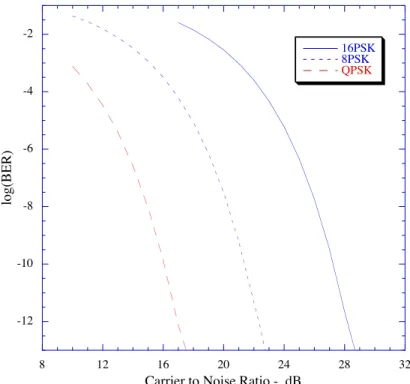
1.1.2 Bit Error Rate Analysis ... 23
1.1.3 RF Output Power ... 28
1.2 PHOTODETECTORS... 31
1.2.1 Recent Photodiode Technology... 32
1.2.2 Three-port Detectors ... 33
1.2.3 Optical Control of MMIC Devices... 33
Summary ... 34
1.3CONCLUSION... 35
1.4 REFERENCES... 36
CHAPTER 2: INJECTION LOCKED DFB LASERS ... 39
2.1 COUPLED-WAVE THEORY OF DFB SEMICONDUCTOR LASERS... 40
2.2 OPTICALLY INDUCED FREQUENCY AND GAIN CHANGES... 42
2.3 INJECTION LOCKING DYNAMIC MODELING... 46
2.3.1 Stability... 47
2.3.2 Numerical Model Implementation ... 49
2.3.3 Injection Regimes... 50
2.3.4 Chirp Reduction and Optical PSK Modulation ... 53
2.3.5 Microwave Generation... 54
2.4 CONCLUSION... 56
CHAPTER 3: EXPERIMENTAL STUDY I, LASER CHARACTERISTICS AND INJECTION LOCKING
PROPERTIES ... 59
3.1 DESCRIPTION OF DFB SEMICONDUCTOR LASERS USED... 60
3.1.1 Laser Chip Assembly ... 60
3.1.2 Static Characteristics ... 61
3.1.3 Modulation Properties... 64
3.1.4 Laser Linewidth ... 66
3.2 INJECTION LOCKING CHARACTERISTICS... 68
3.2.1 Schema and Control Parameters ... 68
3.2.2 Locking Bandwidth ... 69
3.2.3 Injection Regimes... 72
3.3 OPTICALLY INDUCED INDEX CHANGES... 73
3.3.1 OLCR Technique... 74
3.3.2 Reflection Coefficient of a DFB Laser ... 75
3.3.3 Free-Running Lasers at 0 mA Bias... 77
3.3.4 Free-Running Lasers Above Threshold... 78
3.3.5 Injection-Locked Lasers ... 79
3.4 CONCLUSION... 81
3.5 REFERENCES... 82
CHAPTER 4: EXPERIMENTAL STUDY II, MICROWAVE GENERATION ... 84
4.1 EXPERIMENTAL PROCEDURE... 85
4.2MODULATION CONDITIONS FOR THE MASTER LASER... 86
4.2.1 Master Laser Modulation... 86
4.2.2 Free-Running Beating ... 87
4.3 SIDEBAND INJECTION LOCKING CHARACTERISTICS... 88
4.3.1 Locking Bandwidth Overlapping ... 89
4.3.2 Injection Rate Influence... 90
4.3.3 Frequency Detuning Influence... 92
4.3.4 Injection Locking Stability ... 93
4.4 EXPERIMENTAL DEMONSTRATION OF MICROWAVE GENERATION... 95
4.4.1 Optimal Sideband Injection Locking ... 95
4.4.2 Spectral Analysis of RF Frequencies... 97
4.4.3 Influence of the Injection Rate on RF Spectrum ... 99
4.4.4 Transmission Over 30 km of a Single-Mode Fiber... 100
4.4.5 RF Characteristics... 102
4.5 CONCLUSION... 104
List of Figures
Figure 0.1: Different service requirements in terms of session time vs. bandwidth...3
Figure 0.2: A fiber radio system where remote generation and control are carried out at the control station...4
Figure 1.1: Fiber optic transmission of two signals showing the possible photocurrent power spectrums. ...16
Figure 1.2: Delay induced penalty on the carrier to noise ratio...19
Figure 1.3: Phase noise spectrum in function of the frequency...20
Figure 1.4: Phase error in function of the total differential delay...21
Figure 1.5: Total differential delay in function of the transmission distance and carrier frequency product...22
Figure 1.6: Path imbalance needed for fiber dispersion compensation...22
Figure 1.7: Bit error rate in function of the path imbalance for a 15 km transmission distance. ...26
Figure 1.8: Bit error rate in function of the carrier to noise ratio for different modulation formats. ...26
Figure 1.9: Dispersion compensation tolerance at BER of 10-9...27
Figure 1.10: Bit error rate in function of the transmission distance for a carrier to noise ratio of 16 dB and without dispersion compensation. ...27
Figure 1.11: Heterodyning at the photodiode ...28
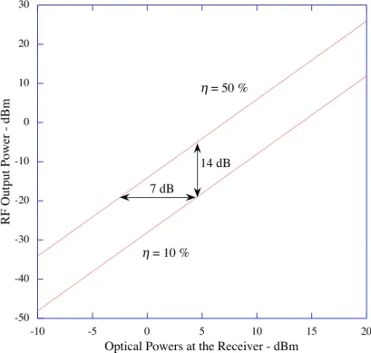
Figure 1.12: RF output power in function of the received optical power of each carrier. ...29
Figure 1.13: RF output power in function of RF input power for several transmission distances. ...30
Figure 1.14: Link gain for two different detector quantum efficiencies (dotted line id for direct detection)...31
Figure 2.1: DFB semiconductor laser structure. ...42
Figure 2.2: Coefficient Cl for the DFB laser structure. ...45
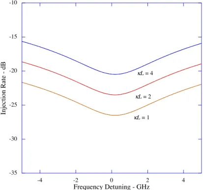
Figure 2.3: Static locking bandwidth for different coupling coefficients. ...46
Figure 2.4: Dynamic limit of the stable locking range for different coupling coeficients. ...48
Figure 2.5: Stable locking bandwidth depicting the different injection regimes...51
Figure 2.7: Operation at the edge of the static locking bandwidth. ...53
Figure 2.8: Nonlinear mixing between the master laser frequency and the slave laser free-reunning frequency...53
Figure 2.9: Self-pulsating regime...53
Figure 2.10: Chaotic behavior provoked by a high injection rate...53
Figure 2.11: Free-running spectrum of the modulated DFB laser. ...54
Figure 2.12: Injection-locked spectrum of the modulated DFB laser. ...54
Figure 2.13: Free-running spectrum of the beat signal between the slave lasers. ...55
Figure 2.14: Power spectrum of the slave lasers synchronized to different IM-FM sidebands. ...55
Figure 2.15: Power spectrum of the beat signal between the injection-locked slave lasers...55
Figure 3.1: DFB Laser structure ...60
Figure 3.2: Mechanical assembly...61
Figure 3.3: Power-current characteristics of the laser diode an its optical spectrum above threshold...62
Figure 3.4: Wavelength dependence on biasing current ...63
Figure 3.5: Wavelength dependence on temperature ...64
Figure 3.6. Modulated master laser optical spectrum with no drive current amplification...66
Figure 3.7. Modulated master laser optical spectrum with drive current 35 dB amplification. ...66
Figure 3.8: Self-homodyne technique for measuring the laser linewidth...67
Figure 3.9: Self-homodyne spectrum. ...67
Figure 3.10: Setup for injection locking experiments. ...69
Figure 3.11: Non-synchronized slave laser spectrum. ...70
Figure 3.12: Theoretical fit (continuous line) and measured data (dots) of the locking bandwidth...71
Figure 3.13: Stable locking (i). ...73
Figure 3.14: Unlocked slave laser spectrum (ii). ...73
Figure 3.15: Relaxation oscillations sidebands (iii)...73
Figure 3.16: Chaotic behavior (iii)...73
Figure 3.17: Experimental setup for the OLCR measurments...75
Figure 3.18: Structure used to calculate the reflectivity coefficient as seen from the fiber/air interface...75
Figure 3.20: Theoretical OLCR data...77
Figure 3.21: Phase of the OLCR data...78
Figure 3.22: Theoretical phase of the OLCR data. ...78
Figure 3.23: OLCR data above threshold...79
Figure 3.24: Calculated reflectrogram above threshold. ...79
Figure 3.25: Complex index changes due to optical injection...80
Figure 4.1: Experimental setup used to optically generate microwaves. ...85
Figure 4.2: Optical spectrum of the modulated master laser. ...86
Figure 4.3: Parasitic modulation of the slave lasers...87
Figure 4.4: RF spectrum without microwave absorbers...88
Figure 4.5: RF spectrum with microwave absorbers...88
Figure 4.6: Locking bandwidth overlapping...90
Figure 4.7: Slave laser spectrum evolution as the injection rate varies. ...91
Figure 4.8: Optical spectrum of the locked slave laser at the injection rate limits for stable locking...92
Figure 4.9: Slave laser spectrum near the positive and negative detuning edge of the locking bandwidth...93
Figure 4.10: Sidebands peak power in function of the modulation depth with the overtone number as parameter...96
Figure 4.11: Beatnote power spectrum of the detected current. ...96
Figure 4.12: Master laser spectrum modulated at 4 GHz. ...97
Figure 4.13: RF Spectrum of free-running beating at 20 GHz. ...97
Figure 4.14: RF spectrum of the beating signal for different injection rates...99
Figure 4.15: Modulated master laser at 3 GHz...100
Figure 4.16: RF spectrum ...100
Figure 4.17: Slave lasers optical spectrum ...101
Figure 4.18: Resulting RF spectrum ...101
Figure 4.19: Slave lasers optical spectrum ...101
Figure 4.20: Resulting RF spectrum ...101
- 1 -
Chapter 0:
INTRODUCTION
In recent years an increasing number of countries have been deregulating their telecommunication markets. Strong competition in these markets force network operators to modernize their infrastructure with special emphasis in satisfying the increasing bandwidth demand of private and small business subscribers. Traditionally, telephone networks were operated by telephone companies. New entrants in the market are cable television operators. The economics surrounding the telecommunication market bring both types of operators in to adopting a short-term approach for modernization of their existing networks. As a result, many of the improvements developed up to now are not compatible with each other. Moreover, they are not able to support high bit rate applications that need a large bandwidth and which are clearly foreseen in the near future.
This calls for innovative solutions and any network proposal should yield a roadmap that identifies the path for introducing new technologies, establishing simultaneously a short and a long-term goal. The short-term goal is to facilitate convergence by designing a universal architecture that allows (i) transparent interconnection of access networks and in-house networks, (ii) incorporating current technologies, and (iii) upgrading towards new technologies and infrastructures. The key interface in this architecture, connecting private and public networks, is referred to as the Residential Gateway (RG). The long-term aim is to reach far beyond the current state-of-technology by progressing to an architecture that will permit integration of advanced optical and wireless technologies, thus building the broadband Residential Area Highway.
Evidently, high quality services will continue to develop. The need for more bandwidth will thus continue to increase and the future home environment will be best served by the implementation of a network that offers high bandwidth and that is flexible in use. It is believed that options such as high bit-rate wireless links inside a small area interconnected to an optical fiber network have the best perspective. These types of systems are referred to as fiber radio systems and as it will be seen, the main idea behind them is to provide interactive broadband applications for the individual user.
0.1 Interactive Broadband Applicactions
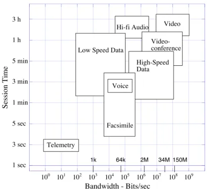
Nowadays a lot of data is transferred in commercial networks for publishing reasons or for videoconferences. In the future, sending of CDs, documents by mail, etc. could also be replaced by data transfer on the information highway. In general, there are four classes of applications in the broadband area: moving images, data communication, mail and messaging, and on-demand services [1]. Moving images include applications as picture telephony, video conferencing, and video surveillance, which by the way, has become increasingly important in the last decade due to security reasons worldwide [2]. Data communication applications are, among others, LAN connections, CAD/CAM connections, and file and image transfer. As for mail and messaging, common transfers will be video-mails, large documents, and exchange of TV programs. Finally, desired on demand services might be teleeducation, data base access, movies on demand, radio and TV streaming, and digital newspaper. All these applications differ form each other in bandwidth, session time and burstiness as outlined in Figure 0.1.
A general view from the final-user perspective could be described as transmission and detection of broadband signals (including voice, data, and/or video) by anyone, anywhere, and at anytime. Current efforts to provide these services are the design of broadband fiber radio access systems, particularly systems like the Local Multipoint Distribution System (LMDS), the Multipoint Video Distribution System (MVDS), and the Mobile Broadband
- 3 -
Hi-fi Audio Video
Session Time 100 101 102 103 104 105 106 107 108 109 1 sec 3 sec 5 sec 1 min 3 min 5 min 1 h 3 h Telemetry
Low Speed Data
Voice Facsimile High-Speed Data Video-conference Bandwidth - Bits/sec 1k 64k 2M 34M 150M
Figure 0.1: Different service requirements in terms of session time vs. bandwidth.
0.2 Justifying Fiber Radio Systems
The microwave frequency band at 25-70 GHz is being considered for fiber radio systems in order to avoid spectral congestion at lower frequencies. These systems may employ hybrid optical/microwave systems since this combination of optics and microwave techniques offers a variety of advantages [4]. First of all, the low fiber attenuation for feeding the base stations is exploited given that transmission of higher radio frequency (RF) carriers by microwave classical means is limited by the attenuation, the noise factor, and microwave circuit dynamics. Concerning the radio link, addition of RF atmospheric attenuation to free space attenuation allows better cell orthogonality and reduces multi-user interference inside a given cell. The use of high RF carriers result then, in a network having a reduced cell-size with more subscribers per area [5]. Moreover, a high frequency-reuse factor is obtainable together with a reduced RF power yielding negligible electromagnetic interference (EMI).
All this leads to a picocellular system having numerous low-cost base stations without microwave oscillators and modulators, and with superior RF properties.
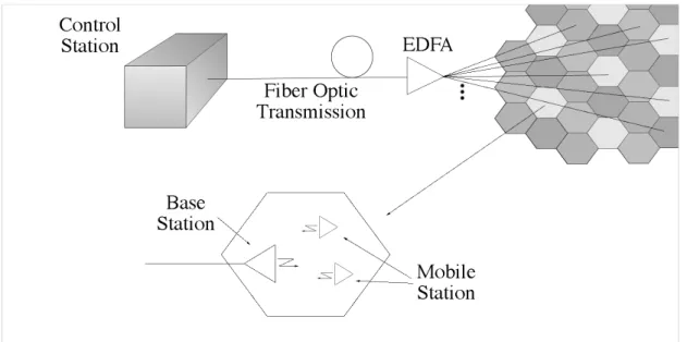
Fiber radio systems, shown in Figure 0.2, comprise microwave components for the radio link between the mobile station (MS) and the base station (BS), and optical components for the optical link between the BS and the control station (CS). These optical components are in charge of the broadband low-loss connection, the generation, and control of the RF signals. Especially in 60 GHz picocellular systems, the costs of the numerous BS’s should be kept as low as possible. Therefore, the generation and control of the microwave signals should be carried out in a centralized manner in the CS, thus obviating the need for microwave oscillators and modulators in the BS’s. In this concept, further functions such as frequency selection and stabilization, signal processing, and network management are performed remotely in the CS. Despite the possibly rough environment of the base station, RF carriers with superior characteristics can be optically generated.
- 5 -
0.3 Exploration of possible techniques
Once having clear that the best solution to fulfill the increasing bandwidth demand is a hybrid optical/microwave network, it is necessary to explore available technologies and identify key problems. In a picocellular system, independently of the services provided, large bandwidth signals will be delivered to numerous base stations. For example, an intelligent vehicle highway system, which will prevent the problem of road accidents and traffic congestion, will require distribution of 60 GHz signals to more than a 1000 remote antenna units (e.g. at traffic lights) that are dispersed over an area with radius just above 10 km [6]. Available standard optical technologies do not permit distribution of signals in this band in a cost-effective way. Innovative solutions have to be proposed keeping in mind that the 1550 nm optical band is mandatory in order to take advantage of erbium-doped fiber amplifiers (EDFA).
The simplest method one can think of is direct modulation of laser diodes, but this is limited by laser bandwidth, chirp and fiber dispersion [7]. Different heterodyne methods have been investigated for the optical generation of microwave signals. In principle, the optical waves can be emitted either from two separate lasers [8], [9] or from a single laser by use of special arrangements. Techniques comprising a single laser include the modulation-sideband-technique [10], dual mode laser [11], externally modulated lasers [12], and mode-locked lasers [13]. It should be noted that most of these techniques require fiber dispersion compensation [14].
There are many other techniques enabling optical generation of microwaves, but are mainly variations of those previously mentioned. For example, instead of using the mode-locked laser technique, self-sustained pulsation lasers could be used to frequency modulate a subcarrier able to reach 100 GHz [15]. Another technique utilizes a phase-locked loop to force a heterodyne signal to track the phase of a reference signal [16]. Still another optical microwave source called an optoelectronic oscillator is based on Brillouin scattering in optical fibers [17]. Following, a brief description of the principal techniques for optical generation of microwaves will be given, outlining their major advantages and drawbacks.
0.3.1 Direct Modulation of Semiconductor Lasers
Direct laser diode modulation, because of its simplicity and wide bandwidth capability, is the most attractive method for generation of a microwave signal at a remote photodetector. For short links the maximum microwave frequency, the link gain, and signal to noise ratio (S / N ) are limited by the laser diode characteristics. Basically, the modulation bandwidth is limited by the relaxation oscillation frequency [18]. Above this frequency, the modulation response falls as 1/ fm2, where fm is the modulation frequency. Although exceeded in
experimental devices [19], the typical modulation bandwidth of a high-speed 1550 nm laser diode is ~20 GHz and represents the practical upper frequency limit. The maximum link gain is limited to -15 dB by the laser slope efficiency and by the reponsivity of the photodetector. The performance depends on the laser intrinsic noise (RIN), which has a resonance at a frequency just below the 3 dB modulation bandwidth. The typical S / N is 50 dB at 18 GHz for 0 dBm drive power and a 1 MHz detection bandwidth [7]. An undesirable feature of direct modulation is the presence of harmonics due to the nonlinearities in the dynamics of laser power vs. current response. In the frequency range of 5 to 15 GHz, the second harmonic to fundamental microwave power ratio is typically -10 dB but can be as little as -5 dB for reasonable (30%) modulation depth and laser bias (Ith). Another disadvantage is the non-flat frequency response, which either has to be compensated for or, in certain applications such as frequency response measurements of optoelectronic components, must be calibrated out. Furthermore, the microwave signal is carried as a lower and an upper sideband on the optical carrier. Due to fiber chromatic dispersion and the large frequency offset between the sidebands and the optical carrier, the phase of each of the spectral components of the transmitted optical signal experiences a differential change. After detection, this results in a power reduction of the recovered microwave signal and thereby a reduction of its carrier to noise ratio C / N .
0.3.2 Modulation Sideband Technique
- 7 -
is its simplicity and low cost. It can support a single very high data-rate channel. A conventional semiconductor laser is externally modulated with a high bandwidth Mach-Zehnder optical modulator. As a result of optical double sideband suppressed carrier modulation, two optical carriers are generated with a frequency difference equal to twice the drive frequency of the modulator. This corresponds to the desired frequency of the microwave carrier. The data modulation is directly applied to the modulator drive signal using a modulation scheme like frequency shift keying (FSK) [10]. This results in an optical output spectrum with two carriers that are frequency shift keyed. The optical signals are transported by a fiber network to the BS where coherent mixing of the carriers generates the electrical microwave signal bearing the FSK data signal.
0.3.3 Dual Mode Laser
Dual-mode multi-section long-cavity distributed feedback (DFB) semiconductor lasers have been developed to generate microwave frequencies up to the 60 GHz range [11]. Two optical modes produced at the output of the device have a frequency separation equal to the desired microwave carrier. The beat signal is produced at a wideband photodetector. To reduce beat phase noise, phase locking of the beat signal is obtained by applying a drive signal to one of the laser sections at a subharmonic of the desired signal. This is a straightforward way of obtaining pure microwaves using a single semiconductor laser chip. Nevertheless, data transmission is not evident. Direct intensity modulation of the laser diode will provoke a simultaneous optical modulation on both modes and a square-law photodetector would eliminate the data PM and FM modulation.
0.3.4 External Modulation Technique
From the viewpoint of cost effectiveness, the external modulation scheme is seemingly a very good solution because of simple configuration [20]. This technique requires a specially designed electroabsorption (EA) modulator with high-efficiency around the desired microwave carrier. This means that a microwave band modulator is required but a wide
bandwidth is not necessary. To overcome chromatic fiber dispersion such as the signal modulation fading phenomenon due to an optical double sideband (DSB) modulation format [21], an optical single sideband (SSB) filtering technique [22] can be adopted. A balanced optical modulation scheme and either a fiber Bragg grating or a Fabry–Perot etalon filter are used to produce the optical SSB signal. The use of optical SSB filter makes possible long standard SMF transmissions (>50 km). Another way to overcome dispersion problems is the use of chirped fiber gratings that for a given distance and carrier frequency a given dispersion compensation must be specified. Although high frequencies can be obtained using this technique (>630 GHz), several drawbacks are accompanied: polarization dependent, nonlinear response, limited modulation depth, additional optical loss, cost, bias drift, frequency chirping and limited power.
0.3.5 Mode-Locked Lasers
In this system, two modes are filtered out from the output of a mode-locked laser and heterodyned at a photodetector. The frequency of the generated microwave corresponds to the longitudinal mode spacing. Active mode locking reduces phase noise and provides a mean to control the generated frequency [13]. Fiber dispersion immunity and full modulation depth are inherent to this technique. The mode-locked laser does not need a mm-wave oscillator but only a low-frequency microwave source. Nevertheless, complex laser structures remain a major drawback.
0.3.6 Sideband Injection Locking Technique
This technique consists in optical heterodyning the signals of two lasers frequency-separated by the desired microwave frequency. The phase noise caused by the spontaneous emission of photons in the laser cavity is cancelled by sideband injection locking with a master laser [8]. The master laser is sub-harmonically modulated so that only low-cost and commercially available microwave components and laser-diodes are required in the CS.
- 9 -
advantages. A great flexibility regarding the microwave frequency is offered since it is given by the frequency spacing of the two lasers. Frequencies from some megahertz up to the terahertz-region are possible. Due to the low phase noise, RF carriers with sub-hertz linewidths can be obtained [5] and bandwidth efficient broadband modulation formats can be applied. The data modulation is simply carried out directly via the laser injection current. In contrast to other optical microwave generation techniques, a further advantage of this method is that the optical power is concentrated only in two optical waves. Thus, it represents a very efficient microwave generation technique, which is also suitable for long distances without degradation due to fiber dispersion. For multi-channel operation, further slave lasers with different optical frequencies are added in optical transmitter. The injection-locked lasers represent a multifunctional element: they act as an optical narrow-band filter, as an amplifier and as a phase modulator with a modulation speed determined by the maximum system bit rate.
0.4 Thesis Overview
Given the undeniable importance the telecommunications market has been acquiring in the past two decades, a thorough examination of available resources to satisfy the increasing bandwidth demand is in place. The numerous advantages of the sideband injection locking technique for optical generation and control of microwaves suggest further scrutiny of the physical mechanisms involved in this technique. Obviously, complete comprehension of the device physical behavior is not sufficient as an objective. A full performance assessment in terms of practical design issues has to be added.
Basically, the topic of this work lies at frontier of the optical and microwave communications fields; a combination of fields frequently called microwave photonics. With the hope to move forward this field, the study of injection locking of distributed feedback semiconductor lasers applied to fiber radio access systems is presented. To accomplish this, an original injection-locked laser model backed up by novel measurement experiments was developed to optically generate and control microwaves.
In the first chapter an introduction to optical heterodyne techniques for microwave generation is given. The choice for heterodyne detection scheme for use in fiber radio access systems was justified earlier. Further insight on this choice is given by a feasibility analysis characterizing link performance in terms of design parameters, such as the dual-frequency optical transmitter, transmission distance, fiber dispersion, differential delays, and carrier frequency. The influence of these parameters on signal to noise ratio, phase noise, bit error rate, and the longest possible transmission distance will be discussed as well. In particular, close attention is given to the output power of the photodetector, which plays an important role on cost reduction and link gain. Finally, the different candidate photodetectors are briefly discussed highlighting the advantages and drawbacks of each.
In chapter two, a semiconductor laser model is developed to accurately describe optical injection in distributed feedback semiconductor lasers. In view of its potentiality in numerous applications it is important to fully describe. Different structures are discussed so as to understand the capabilities of the model. A stability analysis reveals a precise determination of the locking range and the dependency on intrinsic characteristics is established. Large-signal dynamical simulations are carried out using the finite difference method. Applications of the model are finally studied.
In chapter three, an experimental study of the distributed semiconductor lasers used through the thesis is presented. First, the static, noise and modulation characteristics are described through different measurement schemes. Next, the experimental results concerning injection locking of DFB semiconductor lasers and the stabilization procedure are given. An optical low-coherence reflectometer (OLCR) is finally used to measure optically induced index changes.
In chapter four, optically generated microwaves using the sideband injection locking technique is experimentally investigated. After presenting the experimental procedure, conditions on the modulation properties of the master laser are established. Then, sideband injection locking is compared to fundamental peak locking with the objective to find stability conditions. Finally, optical generation of microwaves is experimentally demonstrated and RF properties are discussed.
- 11 -
0.5 References
[1] O. Golda, “Interactive broadband applications, the role of IN,” Intelligent Network Workshop, IN '96., IEEE , 1996.
[2] L. Marchesotti, L. Marcenaro, C. Regazzoni, “A video surveillance architecture for alarm generation and video sequences retrieval Image,” International Conference on Processing. 2002. Proceedings. 2002 , Volume: 1 , 2002 Page(s): 892 –895
[3] D. Budimir, B. Milovanovic, V. Stankovic, “Broadband wireless systems and components-an overview,” Telecommunications in Modern Satellite, Cable and Broadcasting Services, 1999. 4th International Conference on , Volume: 1 , 1999 Page(s): 54 -61 vol.1
[4] R.-P. Braun, G. Grosskopf, D. Rohde, and F. Schmidt, “Low-phase-noise millimeter-wave generation at 64 GHz and data transmission using optical sideband injection locking,” IEEE Photon. Technol. Lett., vol. 10, pp. 728–730, 1998.
[5] R.-P. Braun, “Fibre radio systems, applications and devices,” 24th European Conference on Optical Communication, 1998., Vol. 2 , 1998, pp. 87 -119.
[6] H. Schumuck, R. Heidemann et R. Hofstetter, “Distribution of 60 Ghz signals to more than 1000 base stations”, Elec. Lett., vol 30, pp. 59-60, 1994.
[7] L. Goldberg, R.D. Esman, K.J. Williams, “Optical techniques for microwave generation, transmission and control,” in IEEE MTT-S Int. Microwave Symp. Dig., Microwave Symposium Digest, 1990., IEEE MTTS International , 1990 Page(s): 229 -232 vol.1
[8] L. Goldberg, H. F. Taylor, J. F. Weller, and D. M. Bloom, “Microwave signal generation with injection locked laser diodes,” Electron. Lett., vol.19, pp. 491–493, 1983.
[9] R.-P. Braun, G. Grosskopf, D. Rohde, and F. Schmidt, “Fiber optic millimeter-wave
generation and bandwidth efficient data transmission for 18–20 and 60 GHz-band communications,” in Proc. Int. Top. Meet. Microwave Photonics, MWP’97, Duisburg, Germany, Sept. 1997, pp. 235–238, paper FR2-5.
[10] H. Schmuck and R. Heidemann, “Hybrid fiber-radio field experiment at 60 GHz,” in Tech. Dig. 22th Eur. Conf. Optical Communication, (ECOC’96), Oslo, Norway, Sept. 1996, vol. 4, pp. 59–62, paper ThC. 1.2.
[11] D. Wake, C.R. Lima et P.A. Davies, “Optical Generation of Millimeter-Wave Signals for Fiber-Radio Systems Using a Dual-Mode DFB Semiconductor Laser”, IEEE Trans. Microwave Theory Tech., vol 43, pp. 2270-2276, sept. 1995.
[12] T. Kuri, K. Kitayama, A. Stohr, Y. Ogawa, “Fiber-optic millimeter-wave downlink system using 60 GHz-band external modulation”, Journal of Lightwave Technology, Vol. 17, May 1999 pp. 799 -806
[13] C. H. v. Helmolt, U. Krüger, K. Krüger, and G. Grosskopf, “A mobile broadband communication system, based on mode locked lasers,” IEEE Trans. Microwave Theory Tech., vol. 45, pp. 1424–1430, Aug. 1997.
[14] A. J. Seeds, “Microwave Photonics,” IEEE Trans. Microwave Theory Tech., Vol?. 50, march 2002, pp. 877-887.
[15] X. Wang, G. Li, C. S. Ih, “Microwave/Millimeter-Wave Frequency Subcarrier Lightwave Modulations Based on Self-Sustained Pulsation of Laser Diode”, IEEE J. Light. Technol., vol 11, pp. 309-315, 1993.
[16] Z.F. Fan et M. Dagenais, “Optical Generation of a Megahertz-Linewidth Microwave Signal Using Semiconductor Lasers and a Discriminator-Aided Phase-Locked Loop”, IEEE Trans. Microwave Theory Tech., vol 45, pp. 1296-1300, août 1997.
- 13 -
[17] X.S. Yao, “High-quality microwave signal generation by use of Brillouin scattering in
optical fibers”, Optics Lett., vol 22, pp. 1329-1331, sept. 1997.
[18] G. P. Agrawal and N. K. Dutta, Semiconductor Lasers, 2nd ed. New York: Van Nostrand Reinhold, 1993.
[19] Weisser, S., Larkins, E.C.; Czotscher, K., Benz, W., Daleiden, J., Esquivias, I., Fleissner, J., Ralston, J.D., Romero, B., Sah, R.E., Schonfelder, A., Rosenzweig, J., “Damping-limited modulation bandwidths up to 40 GHz in undoped short-cavity In/sub 0.35/Ga/sub 0.65/As-GaAs multiple-quantum-well lasers”, pp. 608 –610.
[20] K. Kitayama, “Architectural considerations of radio-on-fiber millimeter-wave wireless access systems,” in Proc. 1998 URSI Int. Symp. Signals, Systems, and Electron. (ISSSE’98), Pisa, Italy, Invited Paper, Sept. 1998, pp. 378–383.
[21] K. Kitayama, “Optical DSB signal based mm-wave fiber-radio system using external modulation technique: ultimate performance,” International Topical Meeting on Microwave Photonics, 1999 pp. 53 -56
[22] J. Park, W. V. Sorin, and K. Y. Lau, “Elimination of the fiber chromatic dispersion penalty on 1550 nm millimeter-wave optical transmission,” Electron. Lett., vol. 33, no. 6, pp. 512–513, Mar. 1997.
Chapter 1:
GENERALITIES OF
THE HETERODYNE
DETECTION SCHEME
The microwave photonics field is developing to accomplish RF tasks with optical techniques in a more efficient way, with less cost and with increased capacity. Several transmission experiments incorporating optical/microwave hybrid techniques have been reported ([1] and references within). Nevertheless, numerous questions remain unanswered, particularly on how device characteristics specifically affect link performance and on what techniques favor different applications in fiber radio access systems. The objective of this chapter is then to clarify what the capabilities of a heterodyne detection link are in function of the device parameters and the desired RF tasks. Every system component is equally important so recent photodetector technology will be discussed as well.
1.1 Heterodyne Detection Scheme
Fiber radio access systems using a remote heterodyne detection scheme are based on the simultaneous transmission of two or more optical signals having a strong phase correlation. The optical signals are offset by the desired microwave frequency. This can be achieved for instance, by using any of the heterodyne techniques described in the introduction. It is assumed that the lasers are located at the control station. Otherwise, having a laser at the control station and a laser acting as a local oscillator at the base station would impose frequency control and polarization matching at the receiver, thus elevating the cost of the base station.
Figure 1.1: Fiber optic transmission of two signals showing the possible photocurrent power spectrums.
In Figure 1.1 the general heterodyne detection scheme is shown. Before transmission of both carriers through an optical fiber, each carrier often propagates through separate paths in the dual-frequency optical transmitter. As a result, the path imbalance, !Lpath = L2 " L1,
causes a delay between both signals given by
!path =
L2"n(#2)$ L1" n(#1)
c , Eq. 1.1
where n is the refractive index of the unbalanced path and c the speed of light in vacuum. It should be noticed that this delay could be either positive or negative. Due to chromatic fiber
17
dispersion, each carrier propagates at different speeds and, after a transmission distance L, another delay is added, which is expressed as
!disp = D" L"#2
c " fmw, Eq. 1.2
D is the fiber dispersion taken as 17 ps/km! nm for standard single-mode fibers, ! the mean optical wavelength, and fmw= f2 ! f1 the microwave carrier frequency. The master laser,
from which the two signals are derived in the dual-frequency optical transmitter, is assumed to have a Lorentzian-line power spectrum with a full-width at half-maximum (FWHM)
!"m = Rsp(1+#H) /(4$P0) [2], where Rsp is the rate of spontaneous emission coupled to the
lasing mode [3], !H is the linewidth enhancement factor [4], and P0 is the average output
power per facet. Under these assumptions, the single-sided photocurrent spectrum is calculated following Gallion et al. [5], by taking the Fourier transform of the generated current autocorrelation function to yield:
Si( f )=!2 i 2exp("2#$%
m&0)'( f ) + !
2 i 2 $%m/#
$%m
2 + f2
( 1 " exp("2#$%
{
m&0) cos(2#f&[
0)+ $%m&0sinc(2#f&0)]
}
Eq. 1.3
where f represents the offset from the microwave carrier, !0 =!path +!disp the total delay
between the optical signals [6], ! the relative weight between the amplitudes of each field, and i = (!" e / h#0) E
$
(t)E(t ) is the photocurrent mean value; !, e, h, and !0, representing
respectively, the detector quantum efficiency, the electron charge, the Planck constant, and the optical frequency. The sign of the path imbalance delay depends on whether it works in the same or opposite direction as the dispersion-induced delay. The laser field is modeled as a quasi-monochromatic field stabilized in amplitude E(t )= E0exp j
[
!0t+"(t)]
. The totaldetected field is then taken as the superposition of this field and an image of itself delayed and frequency shifted, ET(t) = E(t) +!E(t +"0)exp( j2#fmwt).
From Figure 1.1, three cases can be distinguished according to the total delay induced through the transmission paths. Case i refers to a large delay with respect to the laser
coherence time (!0 >1/ "#m), and the resulting photocurrent power spectrum is a Lorentzian shaped curve designated by the second term in Eq 1.3. Its full width at half maximum is equal to twice the master laser linewidth. This is due to complete decorrelation of both signals. For intermediate values of the total delay, 0<!0 <1/ "#m (case ii), the output spectrum results in a delta Dirac function superimposed to a sinc function whose spectral zeros are separated by 1/!0. Finally in case iii, when the total delay is zero, both complex amplitudes are perfectly phase correlated so a delta dirac function results.
1.1.1 Differential Delay Influence on Phase Noise
The influence of the differential delay on the carrier to noise ratio C / N and on the phase noise determines the link performance. It is seen from the first term in Eq. 1.3, that an increase in a differential delay results in a decrease of the C / N . Simultaneously, this is accompanied by an increase of the phase noise (second term). For several values of the laser linewidth, the penalty induced on the C / N is represented in Figure 1.2. It can be concluded that for a conventional DFB semiconductor laser, having a linewidth !" ~ 10 MHz, only a small penalty is induced for long differential delays (~ 104
ps). In other words, for a long transmission distance, the chromatic fiber dispersion induces only a small penalty on the
19 0 0,5 1 1,5 2 2,5 3 1 101 102 103 104 1 MHz 10 MHZ 100 MHz
Delay Induced C/N Penalty - dB
Differential Delay - ps Master laser linewidth
Figure 1.2: Delay induced penalty on the carrier to noise ratio.
To study the influence of the differential delay on phase noise, it is best to consider the phase fluctuation spectrum of the generated RF carrier rather than its corresponding power spectrum. Assuming a Lorentzian-line power spectrum for the master laser, the phase fluctuation spectrum is expressed as [7]
S!( f )= 2"#m
$f2
[
1% cos 2$f&(
0)
]
Eq. 1.4This spectrum is shown in Figure 1.3, as a function of the frequency with the total differential delay as a parameter. For an infinite differential delay, the 1/ f2 shape resulting from the
Lorentzian spectrum is clearly identified. For intermediate values of the differential delay, the sinc shape is observed with spectral zeros distanced by 1/!0. And for a small differential delay, the spectrum is fairly constant at small frequency values due to the large separation between spectral zeros. In this case, the filtering performed in the microwave receiver would remove a significant amount of the delay induced phase noise.
10-18 10-17 10-16 10-15 10-14 10-13 10-12 10-11 10-10 10-9 0 2 4 6 8 10 Infinity 1000 ps 100 ps 10 ps
Phase Noise Spectrum - rad
2 /Hz
Frequency - GHz
Figure 1.3: Phase noise spectrum in function of the frequency.
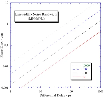
To calculate the exact amount of delay induced rms phase noise !", the receiver noise
bandwidth Bn should then be taken into account giving
(!")2 = S"( f )df 0 Bn
#
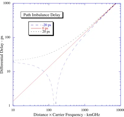
$ 2%&'mBn(0 2 Eq. 1.5This result is only valid for Bn << 1/!0 where the phase fluctuation spectrum is approximated as constant. The rms phase error is represented in Figure 1.4 as a function of the differential delay with the product of the laser linewidth and noise bandwidth as a parameter. It is seen that the phase error increases with an increasing differential delay or with an increasing laser linewidth times noise bandwidth product. In practical systems, for example the INTELSAT earth station [8] where QPSK modulation is used, the maximum allowable rms phase error is 2.2°. The differential delay is shown in Figure 1.5 as a function of the distance times carrier frequency product with the path imbalance delay as a parameter. A wavelength of 1550 nm and a dispersion of 17 ps/km/nm were used. It is observed that the delay increases with transmission distance and carrier frequency. A positive path imbalance delay results in a delay floor equal to its value. The total differential delay can be cancelled for a given distance
21
dispersion delay for a fixed value of the carrier frequency times transmission distance product. The total differential delay is then cancelled leading to a null phase noise. Figure 1.6 shows the path imbalance in function of the transmission distance with the carrier frequency as a parameter. It is seen that a path imbalance of a few centimeters (< 25 cm) suffices to compensate the dispersion induced delay for long transmission distances (~100 km). Even as the microwave carrier frequency increases up to 60 GHz, the compensation distance required remains less than 25 cm.
0,001 0,01 0,1 1 10 1 10 100 1000 10000 1000 100 10
Phase Error - deg
Differential Delay - ps Linewidth ! Noise Bandwidth
(MHzMHz)
1 10 100 1000 10 100 1000 10000 -20 ps 0 ps 20 ps Differential Delay - ps
Distance ! Carrier Frequency - kmGHz Path Imbalance Delay
Figure 1.5: Total differential delay in function of the transmission distance and carrier frequency product.
0 5 10 15 20 25 0 20 40 60 80 100 Path Imbalance - cm Transmission distance - km 20 GHz 30 GHz 40 GHz 60 GHz 50 GHz
Figure 1.6: Path imbalance needed for fiber dispersion compensation.
Even though phase noise can be eliminated under certain conditions, the phase diffusion is a random process so its probability density should be taken unto account in order to quantify its influence on link performance in function of the design parameters. Furthermore it will be seen how sensitive the phase noise effect is to fiber dispersion.