---- 4
3D Printing Dissolvable Support Material for
Time-Dependent Mechanisms
ARCHIVES
OF-by
by
JUN
1
3 2019
Martin Nisser
LIBRARIES
Submitted to the Department of Electrical Engineering and Computer Science
in partial fulfillment of the requirements for the degree of
Master of Science in Computer Science
at the
MASSACHUSETTS INSTITUTE OF TECHNOLOGY
June 2019
Massachusetts Institute of Technology 2019. All rights reserved.
Signature redacted
A uthor ...
...
Department of Electrical Engineering and Computer Science
Signature redacted
May 10, 2019
C ertified by ...
...
Stefanie Mueller
Assistant Professor of Electrical Engineering and Computer Science
Signature
redacted
Thesis Supervisor
A ccepted by ...
...
Leslie A. Kolodziejski
Professor of Electrical Engineering and Computer Science
Chair, Department Committee on Graduate Students
77 Massachusetts Avenue
Cambridge, MA 02139
http://Iibraries.mit.edu/ask
DISCLAIMER NOTICE
Due to the condition of the original material, there are unavoidable
flaws in this reproduction. We have made every effort possible to
provide you with the best copy available.
Thank you.
The images contained in this document are of the
best quality available.
3D Printing Dissolvable Support Material for
Time-Dependent Mechanisms
by
Martin Nisser
Submitted to the Department of Electrical Engineering and Computer Science
On May 10, 2019, in partial fulfillment of the
requirements for the degree of Master of Science in Computer Science
Abstract
In this thesis, a novel approach to the use of dissolvable material is proposed: rather than 3D printing support structures strictly for supporting overhangs, we explore use cases derived from its ability to be dissolved when placed in a solvent, such as water. This enables a range of new use cases, such as quickly dissolving and replacing parts of a prototype during design iteration, printing temporary assembly labels directly onto objects that leave no visual artifacts once dissolved, and creating time-dependent mecha-nisms, such as fading in parts of an image in a shadow art piece or releasing scents from a 3D printed structure sequentially overnight. We use commercially available support material, rendering the approach usable on consumer 3D printers without any further modifications.
To facilitate the design of objects that leverage dissolvable support, a custom 3D editor plugin is built that includes a simulation showing how support material dissolves over time. In our evaluation, our simulation predicted geometries that are statistically similar to the physically dissolved samples within 10% error across all samples.
Thesis Supervisor: Stefanie Mueller
Table of Contents
Introduction... -...-- --- ---- ---...--- - - - 7
Related work...-- - - -- - - - - --...--- 9
Repurposing Fabrication Devices & M aterials ... 9
Optim izing Support Structures ... 10
M odeling Tim e-D ependent Structures ... 10
Project overview ...--.. ...--- --- ----...12
Discrete vs. Continuous Dissolving... 12
Design Tool including Support M aterial Simulation ... 13
Application Use Cases...---... 14
#1: Design Iteration ... .... ---... 14
#2 Breakage Support: D issolvable Packaging (Discrete)... 16
#3 A ssem bly: Tem porary Labels (Discrete)... 18
#4 Overnight Scent Release (Continuous)... 21
#5 Anim ating Shadow Art (Continuous)... ... 23
Sim ulation of D issolving support m aterial ...-... 26
Factors influencing dissolution... 26
Dissolution Sim ulation using kinetic M onte Carlo... 27
Step #1: Voxelizing the M odel... .... 27
Step #2: D issolution Probability... 29
Step #3: Drawing a Random Sam ple... 30
Step #4: Rendering ... 30
Characterizing sim ulation param eters ... 32
Collecting Test D ata ... 32
Im age processing and feature vector extraction ... 33
Im plem entation ... ... --...----... 35
Design Iteration ...-... 35
Breakage Support ... ---.. . -... 38
A ssem bly Instructions ... 39
Tim e-dependent M echanism s: Scent Release and Shadow Art ... 42
D iscussion ... ... 46
Conclusion ... .. --...---... 49
List of Figures
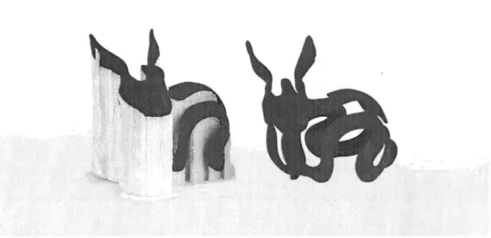
Figure 1 Objects with overhangs can be (Left) 3D printed with support material which can later be
dissolved to produce (Right) the final prototype _ 7
Figure 2. (a) Splitting the model, (b) testing, (c) dissolving the top part before fabricating the next
version. 14
Figure 3 Printing soluble PVA (white) on top of PLA (red) 16
Figure 4 3D printing the phone stand 17
Figure 5. (a) Stress map, (b) generated support material, (c) transportation of the phone stand, and (d)
using the phone stand after dissolving the support material. 18
Figure 6 (Left) 3D printed components of a lamp assembly, (Right) accompanying assembly instructions
19
Figure 7 Manual assembly supported by (Left) labels and (Right) attachments printed from PVA _ 20 Figure 8. (a) Small support structures can be used as connectors, to hold parts in place for (b) later
assembly. (c) Mounting the assembled lamp onto the wall. 21
Figure 9 3D printed, dye-filled capsules in (Above) Simulation and (Below) a physical experiment__ 22 Figure 10 Experimental results after (Top left) 90 minutes, (Bottom left) 120 minutes, (Top right) 160
minutes and (Bottom right) 200 minutes 22
Figure 11. This nightstand box releases relaxing scents in a pre-defined sequence: the red scent first, then blue, and finally green. (a) Simulation, and (b) actual release. 23 Figure 12 Experimental results of the shadow art piece. (Top left) The initial image (Bottom left)
Dissolution of the PVA veneer transitions the sun to a cloud (Top right) Rain drops form and finally
(Bottom right) an umbrella appears in the figure's hand. 24
Figure 13 Here we time the dissolving support to first convert (a) the sun into (b) a cloud, then show the
raindrops, and (c) finally display an umbrella. 24
Figure 14 Factors influencing dissolution 26
Figure 15 Voxelizing the sphere shown on the left produces the geometry to the right 28 Figure 16 Reducing the thickness of the geometry from that of a shelled version of the voxelized model
(Left) to that of a strict thickness of 1 voxel (Right) 29
Figure 17. The more faces of a voxel are exposed to the solvent, the higher the probability that it
dissolves. 30
Figure 18 Rendering of an object showing the section of support material in its (Left) voxelized form
and (Right) following a Laplacian smoothing 31
Figure 19. Dissolution of characterization samples over time. 32
Figure 20. Simulation screenshots. 33
Figure 21. Graph showing the feature vector errors against dissolution time 34
Figure 22 User Interface with model to be partitioned 36
Figure 23 Exporting a partitioned model for printing 37
Figure 24 User interface for breakage support 38
Figure 25 The user interface for the Assembly application permits users to assign temporary attachments
and matching labels to components in an assembly 40
Figure 26 Assembled lamp holder 41
Figure 27 Rendering of lamp holder components after label and connector assignment 42 Figure 28 PVA capsules are filled with scented oils and colored dyes midway through printing 43
Figure 29 Image projection using Shadow art 44
Figure 30 Composite laminate consisting of layers of PVA (white) and PLA (red) material layers, where the dissolution of the former will enable its role as a shadow art piece 45
INTRODUCTION
Since the development of the earliest additive manufacturing techniques in the 1980s, 3D printers have risen rapidly to the forefront of the list of desired and available fabrication machines. Fused Deposition Modeling (FDM) printers in particular have become widespread in both personal and commercial spaces for their ability to deliver cost- and time- efficient prototypes of high quality. These printers operate by feeding thermoplastic through a heated, computer-controlled nozzle that extrudes the material and depos-its it one layer at a time, with each layer cooling to harden before the deposition of subsequent layers.
Figure 1 Objects with overhangs can be (Left) 3D printed with support material which can later be dissolved to produce (Right) the final prototype
Early on in the development of 3D printing, researchers realized that building objects in a bottom-up, layer-by-layer manner was inherently constrained by the fact that particular geometries would have no material underneath them to hold them up (Figure 1). To solve this issue, researchers developed support structures to keep overhangs upright [1, 9]. Early 3D printers that only had a single extruder used one
was not a suitable method for removing support material that had been deposited inside small holes and other unreachable crevasses, as users were not able to reach in to remove it.
More recently, dissolvable material was developed for use in 3D printing. Dissolvable support material [9] solved the aforementioned problems: by undergoing dissolution when placed in an associated solvent such as water, it allows smooth surfaces to be left behind and leaves no visual marks. Since water can better make its way into small crevasses in an object, dissolvable structures can more easily be removed. In addition, solvents like tap water are readily available and cheap- if not free, and once saturated with the dissolved material it can be discarded down regular drains as non-hazardous waste. Due to these benefits, dissolvable support material such as Polyvinyl Alcohol (PVA) are now a widely used alternative to mate-rials that are required to be physically broken off the object.
Since printing support structures requires extra time and material, the use of support has traditionally been perceived as an inconvenient necessity whose purpose is solely to extend the range of printable geometries to those with overhangs. In this thesis, a different approach is taken. Rather than using support material to print support structures, we make use of its transient nature, i.e. the fact that it can be dissolved when placed in a solvent, such as water, to enable a range of new use cases. Specifically, we use the dissolution phenomenon to encode time-dependent mechanisms into otherwise static 3D prints in order to help users with a broad array of tasks, including quickly dissolving and replacing parts of a prototype during design iteration, printing temporary assembly labels directly onto objects that leave no marks when dissolved, and creating time-dependent mechanisms, such as fading in parts of an image in a shadow art piece or releasing scents from a 3D printed structure sequentially overnight. An important aside is that since we use regular support material (PVA) to this end, the materials and techniques developed in this thesis are available for use by any users with access to consumer-grade FDM 3D printers without any further mod-ifications.
The contributions of this thesis include: (1) an exploration of alternative use cases of 3D printable support material in two categories: those that require controlled dissolving behavior for timing and sequencing of events and those that do not need precise control and instead only require the support material to dissolve eventually; (2) a design interface in the form of a 3D editor plugin that facilitates designing with dissolv-able support material; (3) a kinetic Monte Carlo simulation integrated into the design interface that visu-alizes how the support material dissolves over time; and (4) a step-by-step procedure illustrating how to characterize the simulation parameters for different objects.
RELATED WORK
This work is related to research in a variety of disciplines including human-computer interaction and ro-botics, including research aimed at repurposing fabrication tools, optimizing support material, and mod-eling of time-dependent geometries.
Repurposing Fabrication Devices & Materials
Several research projects have investigated how to extend the capabilities of 3D printers by augmenting their traditional workflows. WirePrint [11], for instance, helps users to quickly iterate through prototype designs by extruding material directly into 3D space rather than depositing material layer-by-layer, giving it the ability to fabricate low fidelity protypes with a factor 10 speed-up compared to traditional prints;
3D printed hair [8] repurposes the stringing behavior of plastic extrusion in order to produce hair, fibers
and bristles; and Embedded textiles [18] opens up novel design spaces by embedding fabric layers into a print during 3D printing, for example by printing parallel deposits of material onto a textile in order to limit its flexure along the axis parallel to the deposited segments. Finally, Encore [3] allows users to print on top of or around existing objects in order to extend and augment their functionality, bypassing the need to print a fully functional device from scratch. Of import is that the methods in these publications do not modify the 3D printers used during fabrication, but rather change how they are operated. Building on this benefit shared among the above projects, this thesis aims to leverage existing materials and readily avail-able, low-cost 3D printers to achieve the fabrication and deployment of 3D printed mechanisms such that no specialized material or infrastructure is required on behalf of potential users.
Similar explorations exist for other fabrication processes. For stereolithography-a process in which an object is built layer by layer by selectively illuminating portions of a material that causes chemical mon-omers to link together to form polymers-Cillia [16] generates a stack of bitmaps from CAD models and projects these directly onto a resin in order to enable high-resolution prints; and FusePrint [32] allows users to insert existing objects directly into a resin, letting them produce molds that can be perfectly inter-faced with the existing objects in order to augment their functionality without the need for high-end mod-eling tools or hardware. There also exist a number of projects that have re-purposed lasercutters in order to extend their use cases beyond their traditional space of fabricating 2D veneers. For example,
LaserOri-LaserStacker [24] also delivers rapidly fabricated 3D objects without the need for a manual assembly step by using a defocused laser to weld multiple sheets of acrylic together. Other innovative fabrication tech-niques include Foldem [17], which uses selective ablation of layers in multi-material sheets in a lasercutter in order to fabricate objects with a desired assortment of rigid, flexible and bendable properties. In addi-tion, BlowFab [29] pipelines lasercutting and blow molding procedures in order to produce rapidly fabri-cated 2.5D surfaces by first creating adhesive and inflatable sections on a multimaterial sheet using a lasercutter, before softening these and injecting air into the sheets to produce the final prototypes. How-ever, not all these works support users with a dedicated user interface that lets them readily fabricate devices and structures designed themselves; as part of this work, we plan to integrate the various tools and functionalities we develop into a cohesive user interface with which users can easily fabricate their own custom applications.
Optimizing Support Structures
A number of research projects have developed methods to print support structures in a way that minimizes the overall amount of support material required. For instance, Branching Support [21] and Clever Support
[25] introduce optimization frameworks that minimize the length of support material required, resulting
in tree-like geometries that support overhangs and drastically reduce the amount of printing time and support material required. Bridging Support [4] uses the stringing behavior of plastic extrusion printers in order to build support structures that resemble horizontal bridges. Finally, Perceptual Support [31] lays out support structures in a manner that minimizes visual artifacts. Support structures have also been used for a variety of innovative use cases. For instance, a rampart structure made of support has been shown to work well [6] for preventing smearing of oozed-out material. Closest to our work is Printable Hydraulics [10], which makes use of the liquid support material in inkjet 3D printing as a means of fabricating hy-draulic actuators for robots with pre-filled fluidic channels. Our use of support material positions this work differently to the above projects in that we plan to use support material for purposes entirely different from supporting overhangs, and instead leverage its dissolvability itself for the development of a variety of novel use cases.
Modeling Time-Dependent Structures
In the course of this thesis we also provide a simulation tool that illustrates how support material dissolves over time. In that regard, our work is also related to modeling tools for time-dependent geometries.
Transformative Appetite [26], for instance, simulates the swelling and bending of edible 2D films that fold
into 3D shapes during cooking. The transformation is triggered by water absorption, and a simulation of the process is developed using Finite Element Analysis (FEA). Similarly, BioLogic [30] develops a sim-ulator to model the inner stress and moment equilibriums within biofilms through evolutionary computing techniques in order to preview how these structures curve in the presence of humidity. Other predictive models for the purpose of time-dependent devices have been developed for controlling bending angles in pneumatically actuated devices such as Pouchmotors [13]. In that work, gas tight badders are fabricated by welding and cutting sections of double-layered polyethylene sheet to form McKibben-type pneumatic artificial muscles that can be affixed to otherwise static devices in order to actuate them, and a geometric model is formulated to map the pouches' linear contractions to a hinge folding angle. Predictive models were also developed for the purpose of controlling folding angles in cm-scale self-folding robots by mod-eling the thermal activation of shape memory polymers [14]. In this work, shape memory polymers were embedded in hinges and joule-heated in order to contract, thereby pulling two sides of a hinge together and forcing the surrounding structure to bend; to this end, a thermodynamic model of heat diffusion in the polymer was developed and used with a control algorithm to accurately control the folding angle of the resulting 3D structures. In this thesis, we propose the use of both different classes of modeling techniques and materials in order to enable a novel way of changing an object's shape that differs from both folding and swelling; specifically, we plan to use a probabilistic class of techniques known as Monte Carlo algo-rithms to model the dissolution of commercially available polyvinyl alcohol in order to predict how the shape of a 3D printed object will evolve during a continuous dissolution process.
In the next section, we introduce the scope of this project by making distinctions between two distinct classes of applications we develop, and illustrate how our user interface serves its role as a design tool that permits users to rapidly and easily apply our methods to their own designs.
PROJECT OVERVIEW
The main idea behind this project-known as Sequential Support-is to make use of its ability to be dissolved when placed in a solvent, such as water, to enable a range of new application scenarios.
Discrete vs. Continuous Dissolving
We classify our application scenarios into two categories: (1) discrete and (2) continuous dissolution. In
discrete dissolution, the timing and sequencing of the order in which support material dissolves has no
bearing; it is only of importance that the support material dissolves eventually. For instance, in our first application in which we wish to be able to iterate over multiple different versions of a design, we use dissolvable support material only for that section of an object that requires iteration rather than reprinting the entire object from scratch. After dissolving the section of the prototype part that required a change, we can print the updated section directly on top of the existing object. In this case, it is not necessary to monitor or predict the evolution of the dissolution process itself; rather, we only care that the dissolvable section can be removed entirely in a reasonable space of time. In subsequent applications, we introduce the ideas of using support material to reinforce objects during transport, and later show how dissolvable material can be used to print temporary labels onto components to help users during assembly.
In the case of continuous dissolution, the timing and sequencing of how the support material dissolves does matter. For instance, we can use dissolvable capsules filled with scented oils to release these scents on a night stand overnight in a particular sequence and at pre-defined times. While the discrete applications demonstrate the space of use cases for discrete applications of support material-that is, applications in which we rely only on the fact that the material can be deposited and removed-different benefits arise from the continuous cases in which we leverage the fact that the material changes its shape continuously in time during dissolution. As 3D printed objects have traditionally been static structures, we would like to address this limitation by using the dissolution of PVA to encode mechanisms directly into a print from a monolithic material. Further, we enable this using existing printers and commercial-off-the-shelf support material in order to democratize the process to lay users. By developing a theoretical model of the disso-lution process, we obtain a method by which to design these mechanisms such that we can predict and control the elements of the prints that are subject to time dependency. We develop two applications in order to demonstrate the fidelity of the simulation with regard to its predictive abilities in different ways:
first, in its ability to time and stagger sequential discrete events as a result of continuous dissolution, and second, in its ability to predict a continuous shape change of the material itself.
Design Tool including Support Material Simulation
In order to support both discrete and continuous application areas, we also introduce a design tool that was developed and that is implemented as a Grasshopper plugin to the 3D editor Rhino3D. Users begin by creating a 3D model, then assign either a regular thermoplastic material such as polylactide (PLA) or dissolvable PVA to the different object parts. Once users have assigned the material, the design tool ena-bles a variety of options depending on the application use case selected. For example, for models being inspected as a continuous dissolution example, a slider indicating the total time of simulated dissolution provides the user with a preview of how the support material will dissolve over time. The user can change the object geometry to explore different dissolving outcomes and then choose the design which produces the desired dissolved geometry to export for 3D printing. A more detailed illustration of the design tool and its various features is described in the next section using a variety of different use cases.
APPLICATION USE CASES
In this section, we will describe and evaluate the five applications under representative use cases. We highlight the features and usability of the design tools, report on the fabrication and dissolution durations, and discuss the simulation accuracy.
#1: Design Iteration 44 #Ca
Iteration
Breakag
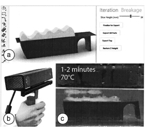
Umc Hoogt (mm)-1 3 ... ... MAW* tT~qFigure 2. (a) Splitting the model, (b) testing, (c) dissolving the top part before fabricating the next
version.
Early in the prototyping stage of designing a physical object, is often necessary to rapidly iterate through many different permutations of a design. However, this rarely entails a full re-design of the entire object or changing its general size, but rather entails updates or variations to certain aspects of the geometry, such as different or additional features-many times just of the aesthetic variety. While 3D printing has allowed users to rapidly fabricate relatively complex geometries in relatively short amounts of time, sig-nificant amounts of time can still be wasted on re-printing an entire object based on an updated design when only a small alteration has been made. Rather than reprinting the entire object during prototyping,
we here propose and develop a pipeline in which users may use dissolvable support material for the parts that require iteration. For example, the designers of an ergonomic handle to be affixed to a Kinect holder may be relatively certain regarding the overall dimensions and size of the holder, but may want to physi-cally construct and iterate on the particular shape of the ergonomic handle itself several times. This would allow them to go through large user studies and receive feedback from a number of potential customers, rather than try to predict what users would want from a theoretical standpoint.
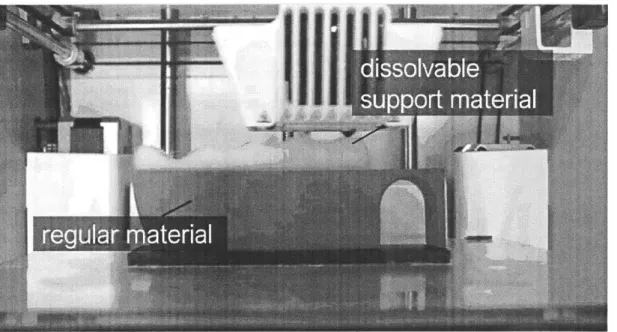
Figure 2 illustrates this discrete application scenario in which a Microsoft Kinect handle has been 3D printed to provide a user with a steadier grip while using the device for 3D scanning. In this scenario, we have not yet ascertained the exact curvature spacing for the ergonomic grip of the holder and thus decide to print this section in dissolvable support material (white in figure) while printing the remaining part-including the rigid attachment that interfaces with the Kinect-in PLA (red in figure).
We use our user interface to split the model into two parts (bottom: red PLA, top: white dissolvable PVA) using the 'slicing height' slider. After printing and testing, we decide to iterate on the design in an attempt to generate a geometry that sports a more comfortable grip. We thus place the entire object into hot water (70'C), which rapidly begins to dissolve and loosen the PVA section of the print and allows it to be removed manually within 1-2 minutes. We return to the 3D editor, modify the 3D model, and export the updated model for 3d printing. To re-print the updated upper portion of the grip, we place the previously printed bottom part back onto the build plate using a custom mount and double-sided tape, and print the new part directly on top of the PLA base (Figure 3).
Figure 3 Printing soluble PVA (white) on top of PLA (red)
Printing the new part took only lh 41 min compared to 5h 16 min to print the object from scratch, yielding a reduction in printing time of 68%. Furthermore, it required 16g material in contrast to 54g for a full re-print; a 71% reduction in material cost. Going through another round of user testing the handle, we con-clude that the design is good and decide to finalize it. We can then place the part once more in water to dissolve the top section of PVA and place the base back in the printer to reprint the handle fully in PLA to produce the final version of the design.
#2 Breakage Support: Dissolvable Packaging (Discrete)
While one long-term vision of the maker community is that one day everyone will own a 3D printer and be able to produce customized physical objects on demand, many people today still rely on and use the 3D printing infrastructure in FabLabs and makerspaces rather than purchasing the machines themselves. In these cases, when users must travel back home with their printed objects-or when 3D printed objects must be transported in general-the objects are generally not packaged or protected to the extent that purchased goods are, and intricately shaped objects can easily sustain damage as the materials used to print them are not particularly robust to breaking. While packaging these objects by hand to protect them would be one option, an automated alternative would be to outsource this task to the 3D printer by auto-matically generating support material around the object as reinforcement. This support material can then
buttress the object during transport and subsequently by dissolved before use, and can furthermore be targeted to only be applied within regions of the object particularly prone to breaking in order to limit printing time and material costs.
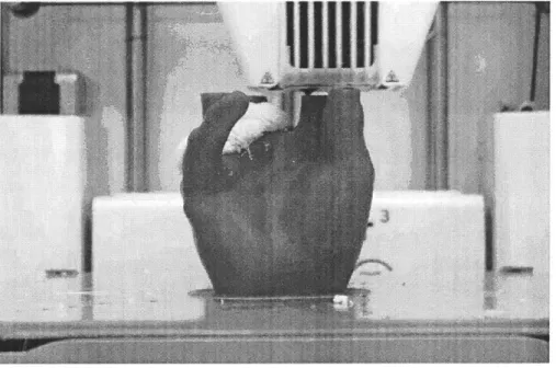
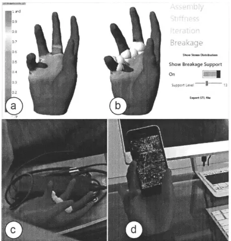
To demonstrate this, we 3D print the mobile phone stand in the shape of a hand shown in Figure 4 in a FabLab. Aware of the relatively fine structure of the fingers, we decide to use support material to reinforce them to prevent them from breaking while transporting them home. Figure 5 illustrates how this is done using our design tool.
Figure 4 3D printing the phone stand
After clicking the 'stress analysis' button in the user interface, Figure 5 (a) shows the resulting heat map of stress distributions, revealing the possibility of the phone stand fracturing in the regions connecting the fingers to the palm of the phone stand. By dragging the 'support level' slider, Figure 5 (b) shows how the regions identified by the stress analysis are targeted to be reinforced with additional dissolvable material. After printing, we place the reinforced phone stand in a bag for transportation (Figure 5 (c)) and on arriving at our destination, we can remove it from the bag to dissolve the support material in water, at which point the product is ready to be used (Figure 5 (d)).
Show Breakage Support
On
b~
Figure
5.
(a) Stress map, (b) generated support material, (c) transportation of the phone stand, and
(d) using the phone stand after dissolving the support material.
Adding the support material increased the total printing time by
just
19% (17h51 vs. 15h01) and required only 6g of support material to be added to the 107g PLA required to print the phone stand. Aftertrans-porting the object home, softening of the support material using hot water (70C) took only 4 minutes
after which we were able to wipe away the remaining material by hand, leaving the object ready to be used within 15 minutes.
#3 Assembly: Temporary Labels (Discrete)
When intending to print an object of a certain size whose dimensions exceed that of a printer's buildplate, it is necessary to split the geometry into components that can be printed separately and then assembled.
Equivalently, there are many objects that may be simpler to design or print by printing them in components even when its overall dimensions are not constrained by the printer volume, and many such objects can
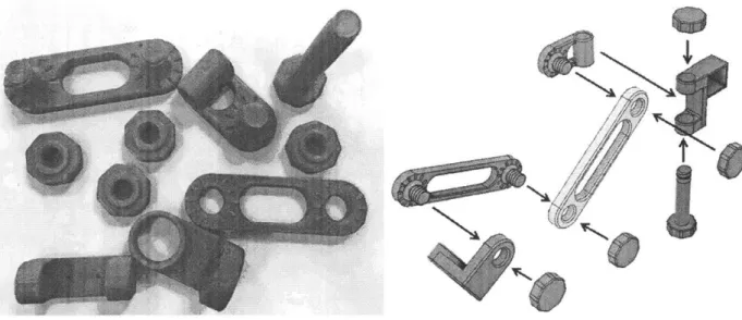
be found on online repositories such as Thingiverse and may or may not come with assembly instructions such as those shown in Figure 6.
Figure 6 (Left) 3D printed components of a lamp assembly, (Right) accompanying assembly instructions
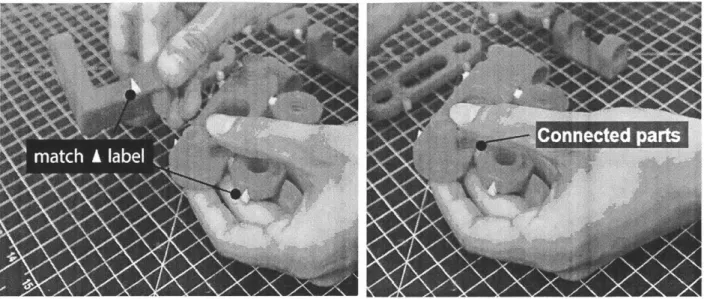
In situations like these, where instructions may be poor or lacking entirely, the assembly process can be a challenging task, particularly when components consist of many modular and identical components or when it is necessary to refer to a separate instruction sheet. Our solution to this is to automate the genera-tion of assembly instrucgenera-tions by auto-generating dissolvable labels on mating component parts, as well as auto-generating temporary attachments between components that should be mated together in order for such pairs to be more easily found. After printing, a user can identify paired components, snap off tempo-rary attachments, and mate these pairs using the labels printed directly onto the components themselves to identify paired components (Figure 7). Following assembly, the entire assembled object can be placed in a solvent in order to dissolve the labels and attachments, leaving the finished prototype void of any visual artifacts.
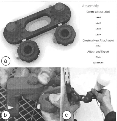
In this use case, we use support material to simplify assembly and demonstrate our workflow using a lamp that consists of 10 different parts. First, we use Sequential Support's user interface (Figure 8) and attach matching labels to the parts of the object that belong together using the 'label' buttons.
Figure 7 Manual assembly supported by (Left) labels and (Right) attachments printed from PVA
Next, we create connectors-small support structures that can be used to connect two parts together (Figure 8 (a)). These structures work as temporary adhesives that place parts that belong together close to each other (for example connecting a nut together with a particular threaded bolt). Users can then break them off during assembly and dissolve them in tandem with the labels (ca. 2-3 min in 70'C).
Create a New Label
Create a New Attachment
Attach and Export
Figure 8. (a) Small support structures can be used as connectors, to hold parts in place for (b) later
assembly. (c) Mounting the assembled lamp onto the wall.
#4 Overnight Scent Release (Continuous)
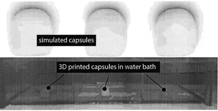
While 3D printed objects have traditionally been static structures, the dissolution of PVA combined with a simulation capable of predicting the evolution of this process allows us to time and stagger sequential discrete events using monolithic blocks of PVA. In this application, we use dissolvable support capsules to release scents overnight at pre-defined times. To this end, we 3D printed three domed cubes from PVA and filled them with scented oils by pausing the print half way through the fabrication process, filling the capsules, and continuing the print as described in Printed Optics [28]. We further added colored dyes to these oils in order to more clearly highlight the release of the oils for documentation. We then placed the
simulated capsules
3D printed capsules in water bath
Figure WQW\\' r , ys)a My a
Figure 9 3D printed, dye-filled capsules in (Above) Simulation and (Below) a physical experiment
Ct
Figure 10 Experimental results after (Top left) 90 minutes, (Bottom left) 120 minutes, (Top right) 160 minutes and (Bottom right) 200 minutes
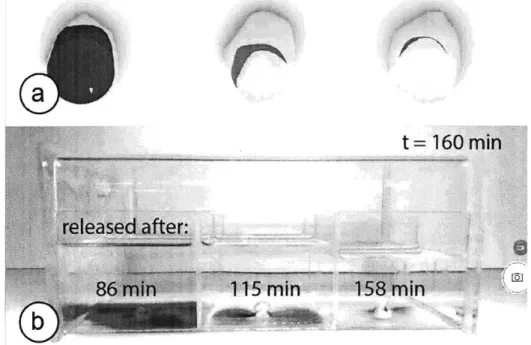
Figure 11. This nightstand box releases relaxing scents in a pre-defined sequence: the red scent
first, then blue, and finally green. (a) Simulation, and (b) actual release.
Since each sphere had a different wall thickness (2.5mm, 3mm, 4mm), the scents were released one after another after 86 min, 115 min, and 158 min respectively. Calculating this sequence using Sequential
Sup-port's simulation tool, we were able to predict associated dissolution times of 86 min, 135 min, and 163
min for the red, blue, and green capsules respectively (Figure 11).
#5 Animating Shadow Art (Continuous)
By leveraging the predictions that our simulation makes with regard to the timing and sequencing of dis-solution for the various parts of an object's geometry, we can also use dissolving support to create a sequence of shadow art images by predicting the continuous shape change of the material itself. Shadow art pieces are a form of art in which 2D shadows are cast onto surfaces by shining a point light source onto a 3D object. Figure 13 illustrates this using a sequence of images: Figure 13 (top left) shows how prior to the support material dissolving, the shadow art shows the initial image of a figure standing under a sunny
-1
Figure 12 Experimental results of the shadow art piece. (Top left) The initial image (Bottom left) Dissolu-tion of the PVA veneer transiDissolu-tions the sun to a cloud (Top right) Rain drops form and finally (Bottom
right) an umbrella appears in the figure's hand.
Figure 13 Here we time the dissolving support to first convert (a) the sun into (b) a cloud, then show the raindrops, and (c) finally display an umbrella.
Once the shadow art starts dissolving, Figure 13 (bottom left) shows the sun transitioning into a cloud, before Figure 13 (top right) shows the raindrops becoming visible, and finally Figure 13 (bottom right) illustrates an umbrella appearing above the figure. The setup that we used to create this sequence consisted of the 3D printed template object submersed in a water container and a light source mounted above it.
Running our simulation in tandem with the physical dissolution (Figure 12), the dissolution time predicted by the simulation was 428 min vs. 380 min taken for the actual dissolving time; the clouds, rain-drops, and umbrella were furthermore qualitatively judged to be dissolved at 1/2, 3/4T and at T, respectively, for both simulation and experiment where T is the total time for dissolution.
SIMULATION OF DISSOLVING SUPPORT MATERIAL
In this section, we provide background information on the various factors that influence how support material dissolves and then discuss how we implemented our physical simulation. Figure 14 provides an overview of the factors involved in dissolving support material, which we extracted from related research on dissolving crystals in solvents [2,5,15].
Factors influencing dissolution
water
temperature
surface area
0
sra
boundary
layer
10
saturation
-
0
o
stirring
of water
00
0
Figure 14 Factors influencing dissolution
The rate at which support material dissolves is directly correlated with the surface area of the support structure exposed to the solvent at a given time. For a given volume, the larger the surface area that is exposed to the solvent, the faster the structure dissolves. This is the reason why geometrically sparse structures dissolve faster than "denser" ones. A higher water temperature also results in a faster diffusion. For the simulation, we assume a constant water temperature of 450C. Moreover, when support material
dissolves, the resulting particles tend to remain in place close to the location at which they dissolved at the object's surface, forming a boundary layer to the rest of the solvent. The greater the PVA content and thickness of the boundary layer, the slower the remainder of the support material will dissolve. Stirring of the solvent helps to remove this boundary layer by circulating particles away from the dissolving object's
surface, resulting in faster dissolution. In our setup, we use a magnetic stirrer that stirs the water at a constant rate of 600 rpm and set this factor to be constant in our simulation. Finally, as an increasing amount of support material dissolves, the water becomes increasingly saturated with PVA which also further reduces the dissolution process by decreasing the concentration gradient between the solute and solvent. In our setup, we use a large water bath to house the experimental setup and assume the changes in saturation to be negligibly small; we therefore treat this factor to be constant as well.
Dissolution Simulation using kinetic Monte Carlo
In the next section, we describe the algorithm used in our support material simulation that enables the
continuous application scenarios. The algorithm is primarily implemented as a Python script within
Grass-hopper; its function is to accept a 3d geometry and render-over several timesteps-how that geometry evolves in time given a set of experimental parameters such as water temperature. To do this, we first discretize the model into voxels in order to find a discrete representation of the object. At every timestep, we then use a probabilistic technique known as a kinetic Monte Carlo algorithm to decide which voxels will be dissolved and therefore removed from the simulation. Since the dissolution process is a stochastic process and an object will not dissolve the exact same way twice, Monte Carlo allows us to produce dissolution profiles that are statistically accurate and that we can characterize and evaluate against physical experiments run in parallel to our simulation.
Step #1: Voxelizing the Model
Once a user assigns PVA to a part of a 3D model, we begin pre-processing of the part in preparation for the dissolution simulation. We begin by voxelizing the part as shown in Figure 15: we first compute the part's bounding box and then fill it with voxels of size N (we use a side length of 0.3mm; smaller values result in higher resolutions and more accurate simulations, at the trade-off of increased computational complexity that limits interactive exploration in the design interface). We then keep all voxels that inter-sect with the part's surface and discard the rest, leaving behind a shell of voxels.
Figure 15 Voxelizing the sphere shown on the left produces the geometry to the right
It is desirable to keep only the surface voxels as every voxel must be accounted for at every time step in the simulation, and so this results in significant computational improvements over tracking every voxel throughout the volume of the object. Moreover, it is only the surface voxels that are of import as these are the only ones that require rendering, as well as being the only voxels with a non-zero chance of being dissolved at any time step (as internal voxels are not in contact with the virtual solvent). However, the intersection test that determines contact with the object's surface is determined by evaluating whether the center of the a given voxel lies within one hypotenuse's Euclidean distance to the closest point on the original object's surface, and this can result in a thickness more than 1 voxel wide, thereby retaining voxels not directly at the surface (Figure 16).
Figure 16 Reducing the thickness of the geometry from that of a shelled version of the voxelized model (Left) to that of a strict thickness of 1 voxel (Right)
In a final step, our algorithm therefore evaluates the surface areas of the two disjoint surfaces of the voxel shell in the model and assigns the smaller of the two to be the internal surface and the other the external surface. Following this check, it can discard all voxels without a face included in the set of faces consti-tuting the external surface area in order to leave behind a shell of voxels just 1 voxel thick.
Step #2: Dissolution Probability
Each remaining voxel can be assigned one of two states: that of dissolving in the current time step or not dissolving. To determine the probability that a voxel will dissolve, we use the equation initially proposed by Gilmer et al. [5] and extended by Briese et al. [2]:
P= V kT
The probability that a voxel dissolves increases exponentially with the number of faces f exposed to the solvent; a voxel that is attached to neighboring voxels or interior material on only one side and thus has 5
face (Figure 17). This supports the intuitive notion that geometrically sparse structures dissolve faster than solid ones.
1 face
Pd = 0.000495 faces
2 faces
P= 0.97 Pd= 0.00324 faces-
3 faces
Pd= 0.1 5 P=0.021Figure 17. The more faces of a voxel are exposed to the solvent, the higher the probability that it dissolves.
In the formula, T is the temperature of the solvent in Kelvin (constant at 318K or 45'C), k is Boltzmann's constant (1.38064852 x 10⁻²³ m2kg/s2K), and v and p are constants parametrizing the material properties that influence the speed of dissolution. We determined v and p for our setup as described in section 'Char-acterizing simulation parameters' (v = 6.5, p = 1.9). The probability for a voxel to dissolve at any time
step is then just a function of the exposed number of faces and is fixed in time for our characterization: ft
= 0.00049, f2 = 0.0032, f3=0.021, f4=0.15, f5=0.97. Step #3: Drawing a Random Sample
We use the above probabilities as inputs to a kinetic Monte Carlo simulation as described in Briese et al. [2]. We begin by drawing a random number n from a uniform distribution on the interval [0,1]. This number is then compared to the probability that each voxel has to dissolve. If the random number is smaller than the dissolution probability of the voxel, the voxel is dissolved. If not, it stays remains in the simula-tion. Following removal of all dissolved voxels in the current time step, new surface voxels are generated in a manner that ensures that the voxel layer remains 1 voxel thick. We then repeat steps #2 and #3.
Step #4: Rendering
In a final step, we convert the voxel model into a continuous surface using a Laplacian smoothing algo-rithm from the Weaverbird [27] Grasshopper add-on to render a more visually compelling result (Figure 18).
Figure 18 Rendering of an object showing the section of support material in its (Left) voxelized form and (Right) following a Laplacian smoothing
CHARACTERIZING SIMULATION PARAMETERS
In this section, we describe how we determine parameters v and p for the dissolution formula by compar-ing provisional results from the simulation to those obtained experimentally.
Collecting Test Data
To determine v and yp, we printed three characterization samples in the shapes of a sphere, an elongated star, and a cube. We submerged them in water to undergo dissolution and captured images using a front view camera (Figure 19) every 8 minutes using a script written in Python. The dimensions of the samples were as follows: the cube featured a side length of 15 mm and the sphere featured a diameter of 15mm, while the 5-point star featured an outside diameter of 24mm and in internal diameter of 12mm, with an elongation of 20mm.
Figure 19. Dissolution of characterization samples over time.
We used a water tank with a capacity of 3 liters and a water temperature of 45'C. This was the highest temperature experimentally observed to be viable based on a trade-off between faster dissolution times and a tendency of the solvent to become cloudy at elevated temperatures, preventing us from being able to capture clear photographs of the samples throughout the course of the experiment.
As the PVA undergoes dissolution, the solvent nearest the material becomes increasingly saturated, form-ing a boundary layer at the objects' surfaces that slows the rate of dissolution. To counter this, we used a
mild current to stir the water using a 20mm magnetic stirrer at 600 rpm. This circulates the solvent around the water tank to help ensure the liquid is uniformly saturated.
In parallel to capturing photographs of the physical dissolution at intervals of 8 minutes, we ran an analo-gous experiment in simulation. Running the simulation with an initial set of estimated values for parame-ters v and p, the three characterization samples were imported as CAD models and virtually dissolved using the kinetic Monte Carlo algorithm while screenshots were taken at regular intervals from the same viewpoint as the physical setup (Figure 20).
Figure 20. Simulation screenshots.
Image processing and feature vector extraction
In order to characterize the simulation parameters, the photographs and screenshots from the experiment and simulation, respectively, must first be processed such that they can be compared. To this end, we used OpenCV, an open source computer vision toolbox, to extract and compare the shape contours. We first thresholded the images to create a binary representation of both photographs and screenshots that shows the sample objects in white, and the backgrounds in black. We then used the huMoments algorithm to extract feature vectors of all images that describe their contours in a translation-, rotation-, and scale-invariant manner.
0
0
.3
A(:D
["I
We then assess the difference between the contours of the physical and virtual geometries by computing the Euclidean distance between their feature vectors. This error is thus based on a comparison of a set of 2D images (a photograph and a simulation screenshot), which we use as a proxy for the difference between the full 3D shapes. The particular geometries dissolved for the purpose of this comparison were for this reason chosen for their symmetry properties, in an attempt to avert problems that may have arisen from attempting to document the dissolution of amorphous shapes in the unobserved third dimension.
Once this error is computed for all images across the full duration of the experiment, we chose another set of simulation parameters and re-ran our simulation, comparing the new errors to those obtained using the previous set of parameters. Parameters were chosen by always first changing p, and then choosing the corresponding v that ensured the probability of a voxel with 5 faces (f5) remained at 97%. We performed
four iterations of parameter tuning and the results for each set of p and v can be seen in Figure 21. We found that (9 = 1.9 and v= 6.5 lead to the lowest mean error between the feature vectors over all time steps
across the three different geometries. The mean score at each time step is obtained by averaging the error from two experiments simulations, with the error between different experiments differing by under 10%.
-8
C
1 -- Star. phi=2.3 - Star, phi=1.9 - - Star, phi=1.5 Star, phi=1.1
o
- Cube, phi=2.3 -- Cube. phi=1.9 - - Cube, phi=1.5 --- Cube, phi=1.10-1 2 3 4 5 7
-I
IMPLEMENTATION
Both the simulation and the use-case specific features in our design tool are implemented as a Grasshopper plugin for the 3D editor Rhino 3D. We used the Human UI library for the user interface (UI) elements. The user interface itself is one and the same for the various applications, with headings that can be clicked on to access the various unique features that support the individual applications.
For the hardware and physical systems, we use an Ultimaker 3 and the associated Cura slicer for 3D printing all models. We furthermore use Ultimaker PVA and PLA as the permanent and dissolvable ma-terials, respectively, and tap water as the solvent for the dissolution process.
Design Iteration
We use HumanUl to make a user interface with which to allow users to quickly and easily upload a 3D model, and partition it into sections to be exported for 3D printing; one to be printed in a rigid material such as PLA or ABS, and another for printing in dissolvable PVA. The partitioning feature was imple-mented using a "slicing" tool that projects a single horizontal plane into a 3D model and which can be manipulated using a slider that translates this slicing plane along the z-axis (vertical axis) perpendicular to this plane. This was evaluated to be the most user-friendly method of sectioning a model into two sections, particularly as partitioning a model into two arbitrarily shaped geometries requires decidedly more complex actions on behalf of the user. However, this does come at the expense of an assumption that the object can be split into two hemispheres, one of which will remain unchanged and another which
will be subject to updates based on user feedback.
The intended workflow of the user interface and this application as a whole is the following:
1. Create a 3D model
2. Launch UI and upload the model
3. Partition the model into two parts: one for iteration and one not.
4. Print the object from scratch in two materials and have users physically evaluate it
5. Until satisfied, repeat:
.4
c. Submerge the latest print in water to dissolve the support material d. Place the remaining part back in the 3D printer
e. Print the updated section in PVA directly onto the existing PLA f. Evaluate the physical print once more.
6. Take the last print, submerge it in water to dissolve the support material 7. Place the remaining part back in the 3D printer
8. Print the most recently updated section in PLA directly onto the existing print 9. Ready for use
d
aeration
Figure 22 User Interface with model to be partitioned
The user interface (Figure 22) includes a slider to set the height at which the model will be partitioned and four buttons; one that finalizes the parts for export by saving and baking the geometry from the grasshop-per plugin into Rhino, another that executes the export itself and converts both native Rhino geometries into STL files, a third button that limits the export process to only output the top segment of the partitioned model, and a final button that resets the partitioning height to its most recent value. The export button saves the generated STL files into a user-specified target folder, and ensures that the two geometries are in the same co-ordinate system such that they can be physically merged during slicing and therefore printed correctly.
To split the model in half at the desired height, we use the Grasshopper SplitBrep() function. On export of the STL files, the two parts are merged into a closed solid using the Grasshopper Cap function. After splitting and capping, the two geometries are baked to a new layer in Rhino using the function GHBake(). We then use a custom script to export each geometry on the GHBake layer as individual STL files, both of which are regular closed meshes, i.e. parts that can contain sparse infills but will be separated by a solid layer.
. . . ... .
Figure 23 Exporting a partitioned model for printing
When printing a new iteration, the system only exports the top geometry as an STL file (Figure 23). We then run a python script in the background that offsets the gcode commands in the Z direction by an amount equal to the height of the PLA part. This avoids users from needing to remember or manually calculate this value themselves. The Python script takes three arguments: first, the path of the file to offset; second, the path of the new file to be created and third, the path of the file that contains the whole object (both PVA and PLA parts). The scnipt searches through this third file to find where in the gcode the printer is instructed to switch materials and finds the last set z-height. It then offsets the z-heights found in the first file by this value and then writes a new file with the new offset z-height.
One particular challenge that arose was during the calibration process of ensuring that the PLA base was placed in the same position on the buildplate during all iterations, such that the updated PVA model would print in the correct location each time. A simple solution to this arose from the fact that the PLA leaves visible artifacts on the buildplate after being removed, so that it could be manually placed back in its original location by eye with good results.
Breakage Support
In this application, we create a tool that allows users to analyze a 3D model in order to determine and visualize its structurally weakest regions; this tool can subsequently autogenerate reinforcing support ma-terial in these locations. Figure 24 demonstrates the user interface in which users can upload a model and run a stress analysis using Finite Element Analysis (FEA). The FEA outputs a heatmap of the stress dis-tributions, highlighting the regions on the object most likely to fracture under a certain loading profile. The user is then able to use the "support level" slider to select how conservative the supporting structure should be by specifying the lower bound of the minimum stress found through the FEA that the support material should reinforce. Support material is then generated in these locations using a simple method by generating overlapping spheres of material in the region.
BreFkg
show BreAMPg Support
Specifically, to create the stress analysis for our model, we use Rhino's Scan&Solve plugin. The plugin comes with a function called AddFaceVectorLoad(), which we give a set of input forces with a uniform load of lOON pointing from the top of the structure to the bottom. To display the resulting stress distribu-tion we use the funcdistribu-tion Soludistribu-tionDisplayEnable). We then get the points subject to the largest stresses using the function QuerySolution Value(), which returns a list of stress values at all points on the model. We sort this list using a custom python script and then create a number of spherical support structures to cover the stress points commensurate with the value chosen using the slider in the user interface. A sphere diameter of 15 mm was an ad hoc choice based on the dimensions of the particular phone holder we printed; however, this could be programmed to scale with the object. The reason 15 mm was chosen as its diameter was furthermore a length that was found experimentally to result in the best quality print jobs. Assembly Instructions
We create the user interface shown in Figure 25 to automate the creation of dissolvable assembly instruc-tions. Enumerated buttons called e.g. "label 1" can be clicked and assigned to several components to be mated, whereby a unique shape such as a triangle will be printed in support material along the side of the components they are affixed to. Similarly, attachments can be generated using another button that assigns a small block of support material to be printed between two components that should be mated during assembly, ensuring that they are printed adjacent to each other. The labelled assembly can then finally be exported for printing using the "Export STL file" button.
R4 W1 n % C.*.* SUsI* S444 h Pnnm TV.ntann ln Amslty *Wc Ppc* $4
Sw0CUto Mwet tnstw etw*nw
-e ewaet'r7enePwusae emt i 40n we -*a y Sy4 pmqn utexrs w u et* imw, ttm e b Twk bftti r T W Stt' ' NO s~ li4 t
~
~
reCleate a New
Labe
par
Create a New Attach
Attach and upon
Figure 25 The user interface for the Assembly application permits users to assign temporary attachments and matching labels to components in an assembly
Figure 26 Assembled lamp holder
For demonstrating these features, we use the 3D model of a modular lamp holder downloaded from Thingiverse, shown following printing and assembly using our tool in Figure 26. The model is made up of 10 constituent components including four nuts and one threaded bolt, and our tool is used in two ways. First, it is used to attach nuts using our connect feature to the components with which the nuts will be mated. Second, labels are attached to all components to indicate the exact location in which mating should occur. Examples of this can be seen in Figure 27, where in addition to the nuts appearing connected to
their associated mating components, different labels in the shapes of a rectangle, a half moon, a triangle and two triangles can be seen affixed on components that are connected to one another.
Figure 27 Rendering of lamp holder components after label and connector assignment
Pinning labels to components in Rhino is done by setting up snap locations on both the object components and the generated instruction labels by generating 'point' objects in Rhino. When a user connects two parts, Rhino's orient() function is called to snap the instruction labels onto the reference points. The same approach is used for the attach option. With this feature, users can upload an assembly and navigate around the various components, adding labels to parts and dragging components together in order to
join
them using connectors.Time-dependent Mechanisms: Scent Release and Shadow Art
For timing of a set of sequential events for the release of scents from a water bath, we fabricate a set of 3D-printed capsules from support material (Figure 28). By filling these with scented oils midway through printing and by altering the wall thickness of capsules themselves, we can mechanically program these to release the scents sequentially, the potential use-case being explored being the sequential release of scents from a waterbath on a nightstand overnight. In addition to filling the capsules with oils, these are also filled with colored dyes in order for the moment of release to be more clearly documented on camera.
Figure 28 PVA capsules are filled with scented oils and colored dyes midway through printing
For the second mode of predicting a continuous shape change, we develop a shadow art piece that morphs between subsequent shapes in order to project a series of images onto a screen (Figure 29). By fabricating a laminate material (Figure 30) consisting of a sub-laminate of PVA of different thicknesses affixed to a veneer of PLA, we can program the dissolution such that the thinner PVA elements dissolve first. When a point light source is directed at the laminate in Figure 30, the image projected by the shadow art piece is initially that of a figure with a sun overhead. This is demonstrated and clarified further in Figure 29, which shows the relative placement of the laminate placed in a water bath, with a point light source over-head that when directed at the shadow art laminate will project an image onto the plane below. The red material in Figure 30 is PLA while the white material is dissolvable PVA, where the cloud is printed with a thickness of 1 mm, the raindrops with a thickness of 2 mm and the umbrella with a thickness of 3 mm. Coarsely, this results in the cloud dissolving first, giving the impression of a sun transitioning into the shape of a cloud in the image. This is followed by raindrops appearing, and ultimately an umbrella ap-pearing in the hand of the figure below.