Publisher’s version / Version de l'éditeur:
Proceedings of the ICEF2006, ICEF2006-1562, pp. 1-11, 2006
READ THESE TERMS AND CONDITIONS CAREFULLY BEFORE USING THIS WEBSITE.
https://nrc-publications.canada.ca/eng/copyright
Vous avez des questions? Nous pouvons vous aider. Pour communiquer directement avec un auteur, consultez la première page de la revue dans laquelle son article a été publié afin de trouver ses coordonnées. Si vous n’arrivez pas à les repérer, communiquez avec nous à PublicationsArchive-ArchivesPublications@nrc-cnrc.gc.ca.
Questions? Contact the NRC Publications Archive team at
PublicationsArchive-ArchivesPublications@nrc-cnrc.gc.ca. If you wish to email the authors directly, please see the first page of the publication for their contact information.
NRC Publications Archive
Archives des publications du CNRC
This publication could be one of several versions: author’s original, accepted manuscript or the publisher’s version. / La version de cette publication peut être l’une des suivantes : la version prépublication de l’auteur, la version acceptée du manuscrit ou la version de l’éditeur.
Access and use of this website and the material on it are subject to the Terms and Conditions set forth at
An experimental and modeling study of HCCl combustion using
n-heptane
Li, Hailin; Guo, Hongsheng; Neill, W. Stuart; Chippior, Wally; Taylor, Joshua
D.
https://publications-cnrc.canada.ca/fra/droits
L’accès à ce site Web et l’utilisation de son contenu sont assujettis aux conditions présentées dans le site LISEZ CES CONDITIONS ATTENTIVEMENT AVANT D’UTILISER CE SITE WEB.
NRC Publications Record / Notice d'Archives des publications de CNRC:
https://nrc-publications.canada.ca/eng/view/object/?id=c498db5c-0b63-4b05-85e7-d4acc487c8c9 https://publications-cnrc.canada.ca/fra/voir/objet/?id=c498db5c-0b63-4b05-85e7-d4acc487c8c9Proceedings of ICEF2006 ASME Internal Combustion Engine Division 2006 Fall Technical Conference November 5-8, 2006, Sacramento, California, USA
ICEF2006-1562
AN EXPERIMENTAL AND MODELING STUDY OF HCCI COMBUSTION USING N-HEPTANE
Hailin Li1, Hongsheng Guo, W. Stuart Neill and Wally Chippior
National Research Council Canada
1200 Montreal Road, Ottawa, ON, K1A 0R6, Canada
Joshua D. Taylor
National Renewable Energy Laboratory 1617 Cole Blvd. Golden, CO 80401,USA
1 Corresponding author, Phone: 613-9494177, Fax:613-9577869, Email: hailin.li@nrc-cnrc.gc.ca ABSTRACT
Homogeneous Charge Compression Ignition (HCCI) is an advanced combustion technology being considered for internal combustion engines due to the potential for high fuel conversion efficiency and extremely low PM and NOx
emissions. In principle, HCCI involves the auto-ignition of a homogeneous mixture of fuel, air and diluents at low to moderate temperatures and high pressure. Previous research has indicated that fuel chemistry has a strong impact on HCCI combustion.
This paper reports the preliminary results of an experimental and modeling study of HCCI engine operation using n-heptane, which has a well known fuel chemistry. The experiments were designed to explore the effects of intake temperature, compression ratio, air/fuel ratio, engine speed and turbo-charging on HCCI combustion.
A numerical model with detailed fuel chemistry was developed to simulate the combustion process in HCCI engines and predict engine performance. The model captured the main combustion stage and its variation in phasing with critical engine parameters.
INTRODUCTION
Homogeneous Charge Compression Ignition (HCCI) is an advanced low temperature combustion technology being considered for internal combustion (IC) engines. In principle, HCCI involves the auto-ignition of a homogeneous mixture of fuel, air and diluents at low to moderate temperatures and high pressure. This approach enables the engine designer to have a high compression ratio, minimize air throttling losses, and rapidly burn the fuel-air mixture near top dead centre, which contributes to high fuel-conversion efficiency. Meanwhile, the burning of a homogeneous fuel-lean mixture at relatively low temperature suppresses the formation of PM and NOx, which are the two problematic emissions from
diesel engines. These desirable combustion characteristics make HCCI a potential future combustion mode for IC engines [1, 2].
HCCI was identified as a distinct combustion phenomenon in the late 1970s. The early works [3-5] investigated the potential of HCCI and recognized the basic characteristics of HCCI combustion. Different approaches for controlling HCCI combustion phasing have been reported [1, 5-7]. It was demonstrated that HCCI combustion has multi-fuel capability compared to traditional IC engines [8]. The recent literature data indicated that fuel chemistry has a strong impact on HCCI combustion. It has been recognized that there is a potential benefit to better understanding the fundamentals of HCCI combustion, and in particular, tailoring a fuel specifically for HCCI combustion [9]. The fuel chemistry of both gasoline- and diesel- like fuels and their mixtures has been investigated [10-12]. In these studies, direct injection (DI) diesel engines were widely adopted due to the increasing interest in adopting HCCI combustion strategies in diesel engines [11]. A traditional low pressure port fuel injector used in S.I. engines has also been used for HCCI combustion research in diesel applications [12].
Apart from the fuel chemistry, the physical properties of liquid fuels and the fuel injection system employed affects the formation of a homogeneous fuel mixture and accordingly the HCCI combustion process [11, 13]. The information obtained may not reflect directly the effect of fuel chemistry, which can not be isolated from fuel injection and atomization processes. The results obtained in different engines may not be consistent. Accordingly, an engine research facility was constructed to focus on the fuel chemistry aspects of HCCI combustion while minimizing the effects of the fuel injection process. The port fuel injection system used in this study was designed specifically to finely atomize a variety of hydrocarbon fuels, which leads to a more homogeneous air/fuel mixture in the combustion chamber before significant oxidation reactions occur [10, 13].
Numerical models have been widely used to explore HCCI fuel chemistry and predict engine performance. Considering the relatively small influence of physical effects such as turbulence and mixing on HCCI combustion as reported in the literature [1], the benefit of
applying a detailed CFD model for HCCI combustion tends to be limited. Also, the large calculation capability required by a CFD model limits the implementation of detailed chemistry, which has been demonstrated to be critically important in HCCI research [14, 15]. Accordingly, single- and multi-zones simulation models have been demonstrated as effective approaches and widely used in exploring HCCI combustion [14-17].
This paper reports the preliminary results of an experimental and modeling study of HCCI engine operation with the focus on n-heptane fuel chemistry. The experiments were conducted in a single-cylinder engine equipped with an air- assist port fuel injector that produced a reasonably homogeneous fuel/air mixture in the combustion chamber. A numerical model with detailed fuel chemistry was developed and validated against engine combustion data obtained in this research and shock tube data reported in literature. It is to be shown that such a model can capture the main combustion phase of a HCCI engine. The effect of critical engine parameters on HCCI combustion can be explored in this set-up and predicted by this model.
EXPERIMENTAL APPARATUS AND PROCEDURE CFR Engine
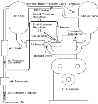
A Co-operative Fuel Research (CFR) engine was used for this research. It is a single-cylinder, variable compression ratio, four-stroke engine commonly used to evaluate the knock resistance of gasoline and the ignition quality of diesel fuels. Table 1 provides the basic specifications of the CFR engine. Fig.1 shows the schematic diagram of the research facility used in this study.
Air Heater
Air Heater
Air Flowmeter
Fuel Pressure Assist Pressure
Air Tank Exhaust Tank
CFR Engine Bypass Valve Fuel Injector Heater Pressure Transducer EGR Valve
Exhaust Back Pressure Valve Exhaust
Air Pressure Reducer Air Pressure
Regulator
Regulator
Compressed Air Controller
Figure 1 Schematic diagram of HCCI engine set-up
The engine was modified from the standard ASTM set-up by the addition of a port fuel injection system and other hardware needed for the control of critical engine parameters such as intake air temperature, air/fuel ratio, recirculation of exhaust gas, and intake air and exhaust back pressure.
Table 1 Engine Specifications Cylinder Bore 82.55 mm Stroke 114.3 mm Displacement 611.7 cc Connecting Rod Length 254 mm Compression Ratio 4.6~16 Combustion Chamber Pancake shape Intake valve open
Intake valve close Exhaust valve open Exhaust valve close
10 CA ATDC 36 CA ABDC 40 CA BBDC 5 CA ATDC
Fuel System Air-assist port fuel injection
Fuel Injection
A port fuel injector for flexible fuel vehicles was modified to provide air-assist atomization of liquid fuels. Such an injector was demonstrated to be able to finely atomize liquid fuels with suitable blast air pressure. For this study, the fuel system and assist-air pressures were maintained at 500 kPa and 200 kPa, respectively. Under these pressures, both diesel- and gasoline-like fuels could be atomized to small droplets with an SMD less than 15 micrometers. The amount of fuel injected was controlled through adjusting the injection pulse width. In this research, the fuel was injected to the intake manifold during the intake stroke. A Coriolis-effect mass flow meter (Micro Motion, Model D6) was used to measure the fuel flow rate.
Intake Air and Exhaust Systems
Surge tanks were installed in the intake and exhaust systems to minimize air pressure pulsations, thereby improving engine operational stability and airflow measurement. The intake air was maintained at specific temperature through precisely controlling the power supplied to a 1.5 kW heater installed after the intake surge tank. Combustion air was supplied by regulated compressed air.
The exhaust surge tank provides complete mixing of the exhaust gases before sampling for emissions analysis and re-circulation into the intake manifold. A back pressure valve was installed at the exit of exhaust surge tank to create the pressure drop needed for EGR operation and simulate the back pressure of the turbocharged engine. The total airflow rate to the engine was measured using a mass flow meter (Sierra, model 780 Series Flat-TrakTM). A portion of the air was diverted to assist in fuel atomization prior to entering the intake manifold.
Data Acquisition
The low-speed data acquisition system is based on National Instruments’ PXI hardware platform. The hardware is controlled by data acquisition and control software (Sakor Technologies, Inc., DynoLAB™ PT), which provided stable control of the engine speed and load conditions, as well as critical parameters such as engine coolant and lubricating oil temperatures, intake air pressure and temperature, exhaust back pressure, fuel injection timing and the quantity of fuel injected.
The cylinder pressure was measured with a high frequency-response piezoelectric pressure transducer (Kistler Corp., model 6121) mounted flush with the cylinder surface using the detonation transducer access port. The transducer was connected to a dual mode charge amplifier (Kistler, model 5010). An encoder fitted to the cam shaft provided a TTL signal with a resolution of 0.1° camshaft (0.2° crankshaft), which was used as the data acquisition clocking pulses to acquire the pressure data and served also as an input to the fuel and blast air injection controlling hardware/software. The resultant pressure and crank angle signals were routed to a high-speed data acquisition system (Optimum Power Technology, model PTrAc), also based on National Instruments’ hardware.
Dynamometer
The engine was coupled to an eddy current dynamometer that absorbed engine load. A variable-speed AC motor, coupled to the dynamometer with an over-drive clutch, was used to start and motor the engine before HCCI combustion was initiated, as well as to maintain engine speed when HCCI combustion was unstable.
Experimental Procedure
Prior to each experiment, the lubrication oil and coolant systems were pre-heated by electric heaters installed in external loops until their temperatures reached 82ºC. At the same time, the intake and exhaust system were warmed up by flowing heated air through these systems. HCCI combustion was easily initiated when the coolant, lubrication oil and fuel/air mixture temperatures reached the required levels. At each operating condition, the engine was run for at least 5 minutes or until engine operation stabilized before sampling experimental data while continually monitoring the main parameters such as intake pressure, temperature as well as the variation of brake power and brake specific fuel consumption (BSFC).
At each operating condition, engine performance data and critical operating parameters were collected for approximately 4 minutes at a sampling frequency of 1 Hz. At the same time, 500 engine working cycles were sampled, saved and processed. The averaged cylinder pressure was analyzed to obtain the heat release and a complete set of combustion parameters. Each cycle was analyzed individually to obtain their statistical data. In this research, pure n-heptane was used as fuel.
NUMERICAL SIMULATION
In order to predict the combustion process of the HCCI engine, a numerical model with detailed chemistry was developed to simulate the four stroke process. The intake stroke was simulated while accounting for the presence of residual gases and fresh charge efficiency measured experimentally. The calculated values of volume, pressure, temperature and composition of the residual gas at exhaust valve closure following prior cycle simulation were used to calculate the mass and thermodynamic property of the residual exhaust gases to be recirculated. The air-fuel-diluents mixture was assumed as an ideal gas with uniform temperature, pressure and mixture composition. When neglecting the effect of blow-by, the energy conservation equation for the whole charge at any instant time
t
from the end of the intake stroke to the end of the expansion stroke is formulated as follows:dt
dW
dt
dU
dt
dQ
=
+
(1)Where:
W
is power output due to piston movement. Its derivative with respect to time,dt
dW
, isdt
dV
P
dt
dW =
(2)Q
is the heat transfer to the cylinder charge. Its derivative with respect to time,dt
dQ
, is)
(
T
T
wA
h
dt
dQ
−
⋅
−
=
(3)where A is the surface area of the combustion chamber wall;
T
is the mean temperature of the charge;T
w is the cylinder wall temperature and considered as constant through simulation process;h
is the heat transfer coefficient, calculated using formulations recommended by Chang, et. al. [18] based on measured spatially averaged heat flux of HCCI engine operation on gasoline.U
is the total internal energy of the cylinder charge. The derivativeU
with respect to time may be calculated as follows:∑
∑
∑
=
+
=
dt
dN
u
dt
du
N
dt
u
N
d
dt
dU
i i i i i i)
(
(4)where Ni is the number of moles of the ith species. It
changes with time as a result of chemical reaction as follows: i i
V
dt
dN
ω
&
=
(5)where
ω
&
iis the production rate of the ith
specie and can be calculated by employing CHEMKIN subroutines based on instantaneous value of mixture composition, temperature and pressure. The other thermodynamic properties such as internal energy and specific heat capacity were also calculated through CHEMKIN with corresponding species property data reported in literature [20].
Effective Fuel/Air Mixture Temperature
In this research, the thermocouple measuring intake mixture temperature was installed about 15 cm upstream of the intake valve. However, the intake mixture is cooled due to fuel evaporation and then continually heated by the intake port and intake valve. Accordingly, the effective fuel/air mixture temperature entering combustion chamber must be estimated. Following the procedure recommended in literature [19], the effective intake temperature
T
in,effective was estimated as follows: base in in air fuel air fuel air base air base effective in effective in P P M M m m T T , , , , , = ⋅ ⋅ ⋅ + + & & (6)where
m
&
air+fuel,M
air+fuelandP
inare the mass flow rate,molar weight and pressure of intake mixture for HCCI operation case,
m
&
air,base, Mair,base andP
in,baseare the mass flow rate, molar weight and pressure of intake air for the base motoring case, andT
in,effective,base is the effective intake temperature for the base case.280 300 320 340 360 380 280 300 320 340 360 380
Intake Air Temperature, K
Effect iv e intake mi x ture t e m p erat ure, K
Figure 2 Variation of effective intake mixture temperature with intake air temperature. N=900 RPM, CR=10.0, Pin=95
kPa, Pexh=104 kPa, AFR=50.
In principle, the base case could be any experimental condition for which the effective intake temperature can be estimated or computed with sufficient accuracy. For this study, motored operation with a Tin of 82ºC was selected as
the base case while the temperature of coolant and lubrication oil was kept at 82ºC. In such a case, transfer from intake port and valve was minimized. The effective fuel/air mixture temperature will be close to the intake air temperature. Figure 2 shows the variation of the effective intake mixture temperature versus intake air temperature of a set of HCCI operation data with constant air/fuel ratio. For low temperature operation, the effective intake mixture temperature is about 20ºC higher than measured intake air temperature. The comparable effective intake temperature value was obtained when intake air temperature reached that of base motoring operation as shown in Figure 2.
Fuel Chemistry
A detailed chemistry, consisted of 561 species and 2539 elementary reactions, was adopted to simulate the ignition process for mixtures of air with n-heptane [20]. This is considered to be the best chemistry for liquid fuels. Model Validation
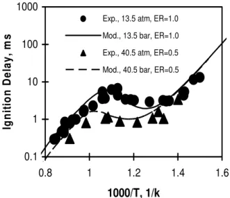
The aforementioned numerical model with detailed fuel chemistry was first validated against shock tube data reported in the literature.
0.1 1 10 100 1000 0.8 1 1.2 1.4 1.6
1000/T, 1/k
Igni ti on De la y , m sExp., 13.5 atm, ER=1.0 Mod., 13.5 bar, ER=1.0 Exp., 40.5 atm, ER=0.5 Mod., 40.5 bar, ER=0.5
Figure 3 Ignition delay of n-heptane at moderate and high pressure for both lean and stoichiometric mixtures. Experimental Data was obtained from [21]
As shown in Fig.3, the predicted ignition delay agrees well with experimental data measured under both stoichiometric and lean operations over a range of temperatures and pressures [21]. This confirms that the chemistry scheme employed can be used to simulate the oxidation process of n-heptane. The model was also compared to pressure traces generated by CHEMKIN IV, a well known commercial software package, for adiabatic HCCI combustion. The model was produced identical cylinder pressure and temperature traces to those produced by CHEMKIN IV.
RESULTS AND DISCUSSION
Fig. 4 shows a typical HCCI combustion trace using n-heptane. The motoring cylinder pressure is shown for comparison purpose. As reported by many other researchers, n-heptane combustion is characterized by a well known two-stage oxidation process. The first two-stage is associated with low temperature reactions (LTR) and releases a relatively small amount of energy. The second stage associated with high temperature oxidation releases most of the energy and is considered as the Main Combustion Stage (MCS). As widely used by other researchers, HCCI combustion phasing was parameterized by the start (CA10), middle (CA50) and end (CA90) of combustion as shown in Fig. 4(b). Among these, CA50 is considered as the most important parameter when describing and optimizing HCCI combustion. As shown in Figure 4 (c), CA50 is located at approximately the middle of main combustion stage. At this condition, our emissions analyzers reported no PM (AVL smoke meter) and less than 2 ppm NOx (California Analytical Instruments), reflecting excellent HCCI combustion. Detailed emissions data will be reported in the future.
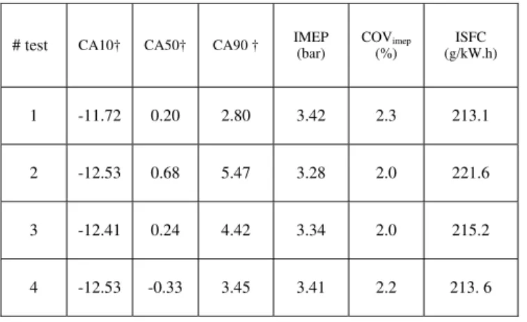
Table 2 compares the combustion and indicated engine performance obtained in different series of experiments conducted in two weeks under the specific operating condition as described. It is demonstrated that the research facility combined with the experiment procedure described earlier is able to produce stable and repeatable HCCI combustion. For example, the maximum differences of CA10 and CA50 among these tests are within 1 ºCA. The COV in imep was found to be about 2% for this operating condition. The best COV in imep obtained in this set-up is about 1% for a HCCI operation using commercial gasoline.
Table 2 Repeatability of HCCI engine operation*
# test CA10† CA50† CA90 † IMEP (bar) COVimep
(%) ISFC (g/kW.h) 1 -11.72 0.20 2.80 3.42 2.3 213.1 2 -12.53 0.68 5.47 3.28 2.0 221.6 3 -12.41 0.24 4.42 3.34 2.0 215.2 4 -12.53 -0.33 3.45 3.41 2.2 213. 6 *CR=10.0, Tin=30ºC, Pin=95 kPa, Pexh=104 kPa, AFR=50.
† CA ATDC
On the basis of these preliminary results, the experimental apparatus was used to investigate the effects of critical engine parameters on HCCI combustion. Details of the experimental matrix are provided in Table 3. The experimental results are shown in Fig. 5~11. 0 10 20 30 40 50 -60 -40 -20 0 20 40 60
Crank Angle, CA ATDC
C yl in d er P ressu re , at m HCCI Combustion Motoring Main Combustion Stage
Low Temperature Reaction
(a) Cylinder Pressure (HCCI via Motoring)
0 20 40 60 80 100 -30 -20 -10 0 10 20
Crank Angle, CA ATDC
C u m u lat ive H ea t R el ease, % 10% 50% 90%
(b) Cumulative Heat Release
0 4 8 12 16 20 -30 -20 -10 0 10 20
Crank Angle, CA ATDC
He a t R e le a s e Ra te , % /CA Low Temperature Reaction Main Combustion Stage CA50
(c) Heat Release Rate
Figure 4 Variation of cylinder pressure, heat release rate and cumulative heat release with crank angle, CR=10, Tin=30ºC, AFR=50, Pin=95 kPa
Table 3 Experiment Matrix # test Speed (rpm) AFR (mass) CR Tin, air, (ºC) Pin, (kPa) 1 600 ~ 1400 50 10.0 40 95 2 900 43~ 63 10.0 30 95 3 900 50, 60 9 ~16 30 95 4 900 50, 60 10.0 25~100 95 5 900 60 10.0 40 95~200 6** 900 20~60 10.0 40 40~95
**Constant fuel flow rate.
0 10 20 30 40 50 -60 -40 -20 0 20 40 60
Crank Angle, CA ATDC
C y li n d e r P res su re, a tm 600 rpm 750 rpm 900 rpm 1000 rpm 1200 rpm 1400 rpm
(a) Cylinder Pressure
0 5 10 15 20 -20 -10 0 10 20 Crank Angle, CA H e at R e le as e R a te , % /C A 600 rpm750 rpm 900 rpm 1000 rpm 1200 rpm
(b) Heat Release Rate
Figure 5 Effect of engine speed on cylinder pressure, heat release rate and negative temperature coefficient (NTC) delay. CR=10.0, Tin=40ºC, Pin=95 kPa, Pexh=104 kPa.
Fig. 5 shows the effect of engine speed on HCCI combustion. Increasing engine speed tends to reduce cylinder pressure and retard peak pressure location, due to a significantly retarded main combustion stage as shown in Fig. 5(b). The heat release rate during MCS is also reduced with retarded combustion phase due to the increasing combustion chamber volume. This tends to reduce the temperature increase resulting from oxidation reaction and correspondingly negatively affect the oxidation reaction rate. However, its effect on low temperature combustion phase tends to be relatively weak, reflecting its relevance to temperature history.
0 10 20 30 40 50 60 70 -60 -40 -20 0 20 40 60 Crank Angle, CA C yl in d er P res su re, at m AFR=43 AFR=45 AFR=50 AFR=55 AFR=58
(a) Cylinder Pressure
0 5 10 15 20 25 30 35 -20 -10 0 10 20 Crank Angle, CA H eat R e lease R a te, % AFR=43 AFR=45 AFR=50 AFR=55 AFR=58
(b) Heat release rate
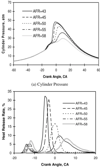
Figure 6 Effect of air-fuel ratio on HCCI combustion. CR=10.0, Tin, air=40ºC, Pin=95 kPa, Pexh=104 kPa, N=900
RPM
Similar to spark ignition and diesel engines, the power produced by an HCCI engine can be controlled by adjusting the amount of fuel supplied or by increasing the intake mixture pressure when turbo- or super-charging is considered. Fig. 6 shows the effect of air/fuel ratio on
cylinder pressure and heat release rate when intake air temperature was kept constant. As shown in Fig. 6(a), the cylinder pressure during MCS is found to increase faster and reach its peak value at an earlier crank angle when more fuel is injected as represented by decreased air/fuel ratio. The advanced main combustion stage combined with the enhanced heat release rate contributes to this phenomenon as shown in Fig. 6 (b). Similar to that of engine speed, the effect of AFR on low temperature heat release rate tends to be very weak, indicating its relevance to mixture temperature history other than mixture composition.
0 20 40 60 80 100 -60 -40 -20 0 20 40 60
Crank Angle, CA ATDC
C y li n d e r P res su re , at m 95 kPa 115 kPa 135 kPa 155 kPa 175 kPa 195 kPa
(a) Cylinder Pressure
0 5 10 15 20 25 -30 -20 -10 0 10 20 30
Crank Angle, CA ATDC
Hea t Rel e a s e Rat e , % /CA 95 kPa 115 kPa 135 kPa 155 kPa 175 kPa 195 kPa
(b) Heat Release Rate
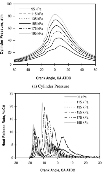
Figure 7 Effect of turbo-charging on HCCI combustion. CR=10, Tin,air=40ºC, AFR=60.0, Pexh=105~120 kPa, N=900
rpm.
The effect of turbo-charging on HCCI combustion was examined at a constant air/fuel ratio. As shown in Fig. 7, boosting intake air pressure tends to significantly increase the cylinder pressure, especially its peak value, which also tends to be advanced. This is mainly due to the increased amount of fuel to be burned. The increased cylinder pressure, which
enhances the oxidation reaction of n-heptane and accordingly advance combustion phase, contributes also to this observation. This tends to improve HCCI performance and reduce the intake mixture heating requirement if late combustion is encountered under ambient conditions as shown in this case. Similar to that of engine speed and air/fuel ratio, boost pressure effect on LTR phase is weak, but boost pressure does enhance to some extent LTR heat release rate as shown in Figure 7(b).
0 10 20 30 40 50 -60 -40 -20 0 20 40 60
Crank Angle, CA ATDC
C y li n d e r P re s s u re , a tm 25 C 41 C 57 C 73 C 89 C
(a) Cylinder Pressure
0 10 20 30 40 -30 -20 -10 0 10 20 30 Crank Angle, CA H eat R el ease R at e, % /C A 25 C41 C 57 C 73 C 89 C
(b) Heat Release Rate
Figure 8 Effect of intake temperature on HCCI combustion. N=900 RPM, CR=10.0, Pin=95 kPa, Pexh=104
kPa, AFR=50.
Intake temperature is the most critical engine operation parameter in controlling HCCI combustion phase. Fig. 8 shows the significant effect of intake temperature on HCCI combustion for constant air/fuel ratio. Stable HCCI combustion can be obtained for a wide range of temperatures. As reported by other researchers and shown in Fig. 8, increasing intake temperature advances both LTR and MCS phase. Also, low temperature reaction heat
release profiles are found to be quiet comparable though they occurred at different phases. However, increasing the intake temperature enhances the heat release rate with an advanced MCS combustion phase as shown in Fig. 8 (b).
Figure 9 shows the effect of compression ratio on HCCI combustion. Increasing compression ratio is found to increase the cylinder pressure especially its peak values. This is primarily due to the increased compression temperature and pressure, both tending to enhance the oxidation reaction rate of n-Heptane. As shown in Fig. 9 (b), both LTR and MCS phases were advanced with increasing compression ratio.
0 20 40 60
-60 -40 -20 0 20 40 60
Crank Angle, CA ATDC
C yl in d er P ressu re, at m CR=10.0 CR=11.0 CR=12.0 CR=13.0 CR=15.0
(a) Cylinder Pressure
0 10 20 30 40 -30 -20 -10 0 10 20 Crank Angle, CA Heat Release Rat e , % /CA CR=10.0 CR=11.0 CR=12.0 CR=13.0 CR=15.0
(b) Heat release rate
Figure 9 Effect of compression ratio on HCCI combustion. CR=10.0, Tin=30ºC, Pin=95 kPa, Pexh=104 kPa, N=900 RPM,
AFR=50.
HCCI combustion tends to be stable and also un-completed when late combustion is encountered. Traditionally, this can be solved through heating intake mixture to a higher temperature or increasing compression
ratio. As reported in literature, enriching air/fuel mixture could enhance oxidation reaction rate [21]. The experiment to determine the effect of AFR on HCCI combustion phase also demonstrated that a relatively richer mixture could also help to advance the combustion phase and accelerate the oxidation reaction toward to a complete combustion. 0 5 10 15 20 25 30 35 -40 -20 0 20 40
Crank Angle, CA ATDC
Cy li nd er P re ssu re , a tm 95 KPa 80 KPa 70 KPa 60 KPa 50 KPa 40 kPa
(a) Cylinder Pressure
0 40 80 120 160 -20 -10 0 10 20
Crank Angle, CA ATDC
H ea t R el e as e R at e, J/ C A 95 KPa 80 KPa 70 KPa 60 KPa 50 KPa 40 KPa
(b) Heat Release Rate
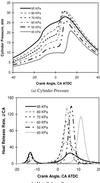
Figure 10 Variation of heat release rate with throttling intake air when intake fuel flow rate was kept constant. N=900 RPM, CR=10.0, Tin=40ºC, Pin=95 kPa, Pexh=104
kPa,
m
&
fuel=
0
.
273
kg
/
h
, AFR=20~60.In HCCI engine, the enriched air/fuel mixture could be obtained through throttling the intake air without increasing fuel flow rate. Fig. 10 shows the effect of intake air throttling on HCCI combustion. Under ambient air pressure, late and un-complete combustion was encountered as reflected by the relatively very weak main combustion stage and lower energy released through combustion. As shown in Fig. 10, throttling intake air
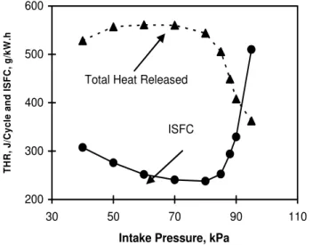
enhances and advances the main combustion stage. This help to burn the fuel completely as indicated by the increased total heat release and reduced ISFC value as shown in Fig. 11. However, over-throttling intake air tends to postpone the main combustion stage again, reflecting the increasingly important effect on HCCI combustion phase of decreased cylinder pressure and the presence of more residual gas, which tends to deteriorate oxidation reaction rate and retard the main combustion phase [22]. The ISFC tends to be increased when the intake air is over throttled as shown in Fig. 11. The increased pumping losses may contribute to this performance deterioration also.
200 300 400 500 600 30 50 70 90 110
Intake Pressure, kPa
TH R , J /Cyc le a nd I S FC , g/ k W .h ISFC Total Heat Released
Figure 11 Effect of throttling intake air on total heat release and indicated specific fuel consumption (ISFC) when intake fuel flow rate was kept constant. Operating condition same as Fig. 10.
The aforementioned single-zone numerical model was used to simulate the HCCI engine combustion process. Fig. 12 compares the simulated cylinder pressure, heat release rate and cumulative heat release with those measured experimentally. For the purpose of comparison, the effective intake mixture temperature used in modeling was adjusted such that the predicted CA50 matched experimental data. The effective intake temperature used in the numerical simulation was 350K compared with the experimental value of 319.5 K as calculated by equation (6). Similar cases have been reported in the literature. For example, Yelvingtin, et al. [23] reported that the intake temperature adjustment was approximately 30 K in order to match the predicted heat release phase with those measured experimentally. This is due to mainly the assumption of homogeneous air/fuel mixture with uniform temperature, pressure, reaction rate and possibly limitation of the fuel chemistry. Mixture temperature adjustments have also been used in multi-zone models to account for non-uniformity of the mixture temperature. For example, the initial temperature difference between the core and outer boundary zones was reported to be ~35 K in one two-zone model to predict reasonably the cylinder pressure and combustion phasing [24].
0 20 40 60
-100 -50 0 50 100
Crank Angle, CA ATDC
C y li n d e r Pr essu re , at m Experiment Model
(a) Cylinder pressure
0 5 10 15 20 25 30 35 -30 -20 -10 0 10 20 30
Crank Angle, CA ATDC
H eat R el ease R at e, % /C A Experiment Model
(b) Heat release rate
0 0.2 0.4 0.6 0.8 1 -30 -20 -10 0 10 20 30
Crank Angle, CA ATDC
C u m u lat ive H e at R el eas e Experiment Model
(c) Cumulative heat release
Figure 12 Comparison of predicted cylinder pressure, heat release rate and cumulative heat release with experimental data measured in this research. CR=10, Tin, air=30ºC,
As shown in Fig 12, the numerical simulation was able to capture elements of the HCCI combustion process for n-heptane, particularly the phasing of the main combustion stage. In comparison, the simulated low temperature reaction tends to be advanced comparing to experimental data as shown in Figure 12 (b) and (c). The spike of the predicted heat release rate during MCS is due to the sudden oxidation of CO accumulated up to this point. On this basis, this model was used to predict the combustion phase of HCCI operation. Unless otherwise specified, the adjustment to effective intake mixture temperature was kept as constant in predicting the combustion phase under other operating conditions.
Fig. 13 shows the effect of compression ratio on CA50. The predicted CA 50 is found to agree well with those obtained experimentally. It is also found that CA50 retards almost linearly with decreasing compression ratio (CR) for high compression ratio (CR>11). However, CA50 retards quickly with decreasing CR when lower compression ratio is adopted.
-20 -15 -10 -5 0 5 10 15 8 10 12 14 16 Compresion Ratio CA 5 0 , CA AT DC Experiment Modeling
Figure 13 Comparison of the predicted CA50 with those determined experimentally over a range of compression ratio. Operating condition same as Fig. 9
Fig. 14 compares the variation of predicted CA50 location with those experimentally. Such a model is shown to be able to capture the effect of engine speed on CA50. Linearly retarded CA50 is observed with increasing engine speed. The effect of turbo-charging on CA50 can be found in Fig. 15. In these prediction cases, the effective intake mixture temperature was adjusted to such that the predicted CA50 matched experimental data when operated under ambient pressure. Such an adjustment was kept as constant in predicting the combustion phase under other operating conditions. As shown in Fig. 15, such a model is found to be able to capture the CA50 variation trend with boost pressure. Boosting intake mixture pressure tends to advance the combustion phase benefiting from the increased cylinder pressure, which tends to enhance the oxidation reaction of n-heptane with air. Under higher pressure, the model reported retarded CA50 in comparison to experimentally observed values. The constant combustion chamber wall temperature
used in this model may contribute to this difference. The variation of combustion wall temperature with load should be considered especially when turbo-charging is adopted considering its significant effect in boosting engine performance and thermal load of combustion chamber.
-10 -8 -6 -4 -2 0 2 4 6 8 10 500 700 900 1100 1300 1500 Engine Speed, rpm CA5 0 , CA AT DC experiment model
Figure 14 Comparison of the predicted CA50 with those determined experimentally over a range of engine speed. Operating condition is the same as in Fig. 5.
-20 -15 -10 -5 0 5 10 15 20 80 100 120 140 160 180 200 220
Intake Pressure, kPa
CA5 0 , CA AT DC Experiment Model
Figure 15 Comparison of the predicted CA50 with those determined experimentally over a range of intake pressure. Operating condition is the same as in Fig. 7
CONCLUSIONS
Based on the experimental and numerical simulation of HCCI combustion using n-heptane, the following conclusions may be drawn:
• Increasing intake air temperature and compression ratio advances combustion phase of both low temperature reaction and main combustion stage. The effects of air/fuel ratio, engine speed and turbo-charging on the low temperature reaction are weak, but significantly affect the phasing of the main combustion stage.
• Throttling the intake air supply while keeping fuel flow rate constant, tends to improve HCCI combustion toward a more complete and stable one if combustion phase tends to be late under ambient conditions. The relatively enriched air/fuel mixture contributes to this desirable characteristic. However, over throttling tends to retard main combustion stage and deteriorate HCCI engine performance though relatively complete combustion can still be obtained at a later phase.
• The numerical simulation captured the main combustion stage of the HCCI combustion process. The predicted CA50 was found to agree well with those measured experimentally over a range of engine compression ratios, speeds and intake air pressures.
ACKNOWLEDGEMENT
The financial support of Government Canada’s PERD/AFTER program is gratefully acknowledged. The technical contribution of Mr. M. F Baksh in constructing the fuel delivery system is greatly appreciated.
REFERENCES
1. Epping, K., Aceves, S.M., Bechtold, R.L. and Dec, J.E., The Potential of HCCI Combustion for High Efficiency and Low Emissions, SAE Paper 2002-01-1923, 2002.
2. Zhao, F., Asmus, T, Assanis, D., Dec, J., Eng, J., and Najt, P, Homogeneous Charge Compression Ignition (HCCI) Engines: Key Research and Development Issues, Society of Automotive Engineers, Inc., 2003. SAE PT-94.
3. Onishi, S., Jo, S.H., Shoda, K., Jo, P.D., and Kato, S., Active Thermo-Atmosphere Combustion (ATAC)--A New Combustion Process for Internal Combustion Engines, SAE Paper 790501, 1979.
4. Noguchi, M., Tanaka, Y., Tanaka, T., and Takeuchi, Y., A Study on Gasoline Engine Combustion By Observation of Intermediate Reactive Products During Combustion, SAE Paper 790840, 1979
5. Najt, P.M., and Foster, D.E., Compression-Ignited Homogeneous Charge Combustion, SAE Paper 830264, 1983.
6. Chen, R. and Milovanovic, N., A Review of Experimental and Simulation Studies on Controlled Auto-Ignition Combustion, SAE Paper 2001-01-1890
7. Yang, J., Culp, T., Kenney, T. Development of a Gasoline Engine System Using HCCI Technology - The Concept and the Test Results, SAE Paper 2002-01-2832, 2002.
8. Christensen, M., Hultqvist, A., and Johansson, B., Demonstrating the Multi-Fuel Capability of a Homogeneous Charge Compression Ignition Engine With Variable Compression Ratio, SAE Paper 1999-01-3679.
9. Kalghatgi, G. T., Auto-ignition Quality of Practical Fuels and Implication for Fuel Requirements of Future SI and HCCI Engines, SAE Paper 2005-01-0239, 2005.
10. Amann, M., Ryan. T.W., and Kono, N., HCCI Fuels Evaluations-Gasoline Boiling Range Fuels, SAE Paper 2005-01-3727.
11. Ryan, T.W., Callahan, T.J., and Mehta, D., Hcci in a Variable Compression Ratio Engine - Effects of Engine Variables, SAE Paper 2004-01-1971.
12. Zhong, S., Megaritis, A., Yap, D., and Xu, H., Experimental Investigation into HCCI Combustion Using Gasoline and Diesel Blended Fuels, SAE Paper 2005-01-3733.
13. Li, Y., Zhao, H., Brouzos, N., Ma, T., and Leach, B., Effect of Injection Timing on Mixture and CAI Combustion in a GDI Engine with an Air-Assisted Injector, SAE Paper 2006-01-0206
14. Easley, W., Agarwal, A., and Lavoie, G.A., Modeling of HCCI Combustion and Emissions Using Detailed Chemistry, SAE Paper 2001-01-1029.
15. Naik, C., Pitz, W.J., Sjoberg, M., Dec, J.E., Orme, J., Curran, H., Simmie, J.M., and Westbrook, C.K., Detailed Chemical Kinetic Modelling of Surrogate Fuels for Gasoline and Application to An HCCI Engine, SAE Paper 2005-01-3741.
16. Xu, H, Modelling of Hcci Engines: Comparison of Single-Zone, Multi-Zone and Test Data, SAE Paper 2005-01-2123
17. Kongsereeparp, P., Kashani, B., and Checkel, M.D., A Stand –Alone Multi-Zone Model for Combustion in HCCI Engines”, ASME ICEF2005-1241, ASME ICED 2005 Fall Technical Conference, September 11-14, 2005, Ottawa, Canada.
18. Chang, J., Guralp, O., Asanis, D., Kuo, T., Najt, P., and Rask, R., New Heat Transfer Correlation for An HCCI Engine Derived From Measurements of Instantaneous Surface Heat Flux, SAE Paper 2004-01-2996.
19. Sjöberg, M., and Dec, J.E., An Investigation of the Relationship Between Measured Intake Temperature, BDC Temperature, and Combustion Phasing for Premixed and DI HCCI Engines, SAE Paper 2004-01-1900.
20. Curran, H.J., Gaffuri, P., Pitz, W.J., and Westbrook, C.K., A Comprehensive Modeling Study of n-Heptane Oxidation, Combustion and Flame, Vol. 114 (149~177), 1998.
21. Ciezki and Adomeit, Shock-Tube Investigation of Self-Ignition of n-Heptane-Air Mixtures under Engine Related Conditions, Combustion and Flame, 93 (1993) 421-433. 22. Peng, Z., Zhao, H., and Ladommatos, N., Effect of Air/Fuel Ratios and EGR Rates on HCCI Combustion of n-Heptane, a Diesel Type Fuel, SAE Paper 2003-01-0747. 23. Yelvington, P.E., Rallo, M.B., Liput, S., Tester, J.W., Green, W.H. and Yang, J., Prediction of Performance Maps for Homogeneous-Charge Compression-Ignition Engines, Combustion Science and Technology, 176: 1243-1282, 2004.
24. Kongsereeparp, P. and Checkel, M.D., Investigation of the Effect of Reformed Fuel Blending in a Natural Gas-HCCI Engine Using a Multi-Zone Model, Combustion Institute/Canadian Section 2006 Spring Meeting, May 14-17, 2006, Waterloo, On, Canada.
