Publisher’s version / Version de l'éditeur:
Proceedings of a symposium sponsored by the Magnesium Committee of the
Light Metals Division of The Minerals, Metals and Materials Society (TMS), 2012,
pp. 449-454, 2012-05-12
READ THESE TERMS AND CONDITIONS CAREFULLY BEFORE USING THIS WEBSITE. https://nrc-publications.canada.ca/eng/copyright
Vous avez des questions? Nous pouvons vous aider. Pour communiquer directement avec un auteur, consultez la
première page de la revue dans laquelle son article a été publié afin de trouver ses coordonnées. Si vous n’arrivez pas à les repérer, communiquez avec nous à PublicationsArchive-ArchivesPublications@nrc-cnrc.gc.ca.
Questions? Contact the NRC Publications Archive team at
PublicationsArchive-ArchivesPublications@nrc-cnrc.gc.ca. If you wish to email the authors directly, please see the first page of the publication for their contact information.
NRC Publications Archive
Archives des publications du CNRC
This publication could be one of several versions: author’s original, accepted manuscript or the publisher’s version. / La version de cette publication peut être l’une des suivantes : la version prépublication de l’auteur, la version acceptée du manuscrit ou la version de l’éditeur.
For the publisher’s version, please access the DOI link below./ Pour consulter la version de l’éditeur, utilisez le lien DOI ci-dessous.
https://doi.org/10.1002/9781118359228.ch82
Access and use of this website and the material on it are subject to the Terms and Conditions set forth at
The role of intermetallics on creep behaviour of extruded magnesium
alloys
Fletcher, Michelle; Bichler, Lukas; Sediako, Dimitry
https://publications-cnrc.canada.ca/fra/droits
L’accès à ce site Web et l’utilisation de son contenu sont assujettis aux conditions présentées dans le site LISEZ CES CONDITIONS ATTENTIVEMENT AVANT D’UTILISER CE SITE WEB.
NRC Publications Record / Notice d'Archives des publications de CNRC:
https://nrc-publications.canada.ca/eng/view/object/?id=86fe95bb-fd4d-4dbb-a5cb-e5ec7ec5969d
https://publications-cnrc.canada.ca/fra/voir/objet/?id=86fe95bb-fd4d-4dbb-a5cb-e5ec7ec5969d
The Role of Intermetallics on Creep Behaviour of Extruded Magnesium Alloys
Michelle Fletcher1, Lukas Bichler1, Dimitry Sediako21UBC Okanagan; 1137 Alumni Way; Kelowna, British Columbia, V1V 1V7, Canada 2NRC-CNBC; Chalk River Laboratories; Chalk River, Ontario, K0J 1J0, Canada
Keywords: Magnesium, Neutron Diffraction, Creep, Microstructure
Abstract
This research examined in-situ creep behavior of three extruded high performance magnesium alloys (AE42, AJ32 and ZE10). Neutron diffraction was used to measure compressive creep behavior at 175°C in the extrusion direction. The AE42 and AJ32 alloys exhibited higher creep strains than the ZE10 alloy. The highest strain was recorded for AE42 (2.4%), while ZE10 exhibited greatest creep resistance (0.2% strain). Microstructure analysis has shown that the distribution and composition of secondary phases was critical for creep resistance. The aluminum containing alloys had acicular and globular intermetallics, whereas the ZE10 alloy contained fine and irregular intermetallics dispersed along grain boundaries, effectively contributing to pinning of grains under high temperature loads. Significant grain re-crystallization was also observed in the aluminum containing alloys, but was absent in ZE10.
Introduction
Ever increasing demand for energy efficient, yet high performance vehicles in the automotive and aerospace industries has resulted in a high demand for light weight structural components. Magnesium (Mg) alloys are the lightest structural materials available with a high specific strength. Further, Mg alloys are easy to machine and cast, with a good potential for recycling [1], establishing themselves as good candidate materials for diverse industrial applications. However, Mg alloys do not have the required creep resistance for automotive applications with operating temperatures above 125°C [2]. This restriction greatly limits their use for automotive components, such as engine block parts, where the greatest impact on fuel efficiency and performance could be achieved [3]. The poor creep strength has been traditionally related to grain boundary movement and plastic deformation which leads to inter-granular failure [4].
Effect of Alloying Elements on Creep Performance
The addition of aluminum (Al) has been known to increase castability and room temperature strength; however, this strength drastically diminishes above 120°C [3]. The main contributing factor to this drop in strength has been related to the presence of the metastable Mg17Al12 intermetallic compound (β phase) along
the grain boundaries. This eutectic compound has a low incipient melting temperature, thus enabling relative sliding of adjacent grains during creep [5]. The Mg17Al12 precipitates form in a
lamellar structure along grain boundaries as well as within grains through a solid state phase transformation [6].
The addition of rare earth elements (REs) such as lanthanum, praseodymium, cerium, and neodymium are known to increase creep resistance of Al-containing Mg alloys. Their beneficial effect has been attributed to the formation of thermally stable intermetallic compounds of diverse morphologies along the grain boundaries. These compounds tend to take the composition of (Mg, Al)xREy due to the low solubility of REs in the Mg matrix
[7]. The formation of AlxREy decreases the Al concentration
within the alloy matrix, thereby decreasing the amount of available Al for the formation of Mg17Al12 [6]. This results in an
improvement of creep resistance.
The addition of strontium (Sr) to Al-containing Mg alloys has a similar effect on the creep resistance as adding REs. The Sr addition causes the formation of thermally stable MgxAlySrz
intermetallic compounds along the grain boundaries [8]. This inhibits Al saturation within the matrix and subsequent Mg17Al12
formation. One benefit of adding Sr over REs is the decreased relative cost associated with the Sr addition.
Zinc (Zn) addition to Mg alloys increases room temperature strength, forms intermetallic particles along grain boundaries and raises the eutectic temperature. The increased eutectic temperature raises the alloy operating temperature [9]. However, Zn addition also increases the alloy’s susceptibility to microporosity and embrittlement [5], thus negatively affecting alloy performance. The addition of REs to Zn-containing Mg alloys increases creep resistance through the formation of thermally stable intermetallic compounds and decreases the susceptibility to microporosity and alloy embrittlement [6]. In these alloys the intermetallics tend to take the composition of (Mg, Zn)xREy and form along the grain
boundaries, effectively pinning grains at elevated temperatures as high as 420°C [1, 9].
In this research, the morphology and distribution of intermetallic compounds in the AE42, AJ32 and ZE10 alloys was investigated and related to the compressive creep performance of the alloys.
Experimental Setup
The alloys analyzed in this research were produced by Timminco Corp., and their nominal compositions are provided in Table I. The three alloys studied (AE42, AJ32 and ZE10) were processed via hot extrusion. No processing defects, such as cracking or solute segregation were observed. Material samples with a torus geometry were produced, as seen in Figure 1a, with an outer and inner diameter of 25 mm and 7 mm, respectively. The microstructure was studied by sectioning the sample into radial and cross-section directions, as can be seen in Figure 1b. Of particular interest was the cross-section surface, since grain elongation in the cross-section direction coincided with the extrusion direction.
Magnesium Technology 2012
Edited by: Suveen N. Mathaudhu, Wim H. Sillekens, Neale R. Neelameggham, and Norbert Hort
Table I. Alloy compositions.
AE42 AJ32 ZE10
Al 3.5-4.5 3-3.5 ≤0.05 Zn ≤0.2 ≤0.3 2.5-3.1 Mn 0.2-0.5 0.2-0.5 0.2-0.5 Fe ≤0.01 ≤0.01 ≤0.01 Ni ≤0.005 ≤0.005 ≤0.005 Cu ≤0.05 ≤0.05 ≤0.05 Si ≤0.05 ≤0.05 ≤0.05 RE 1.5-2.5 2.5-3.5 Sr 1.5-2.5 Zr 0.45-0.7
Figure 1. a) Extruded torus and b) sample surfaces. Neutron Diffraction: Strain Measurement
Compressive creep strain measurement was performed at the Canadian Neutron Beam Center (CNBC) in Chalk River, ON, Canada. A detailed description of the testing procedure was published earlier [10]. Elastic strain (ε) of the atomic lattice was
measured using the peak shift method. This method calculates strain using the change in lattice spacing, as seen in Equation 1: � = (�0− �)
�0
� (1)
Where �0 and � are the lattice spacing before and after creep,
respectively. The lattice spacing was calculated using Bragg’s law (Equation 2):
�� = 2����(�) (2)
Where � is the neutron wavelength (1.792 Å), n=1 for first order diffraction, and � is the neutron scattering angle measured during the neutron diffraction experiment.
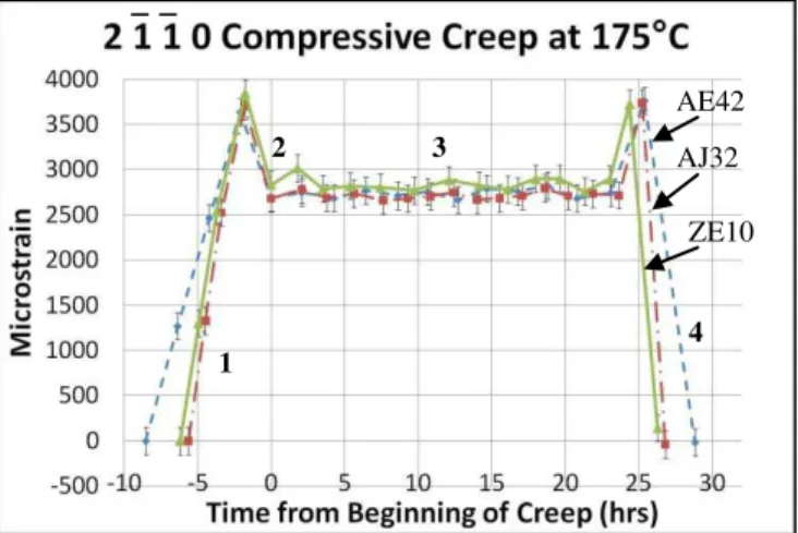
The strain in the 101�0 and 21�1�0 planes were measured parallel to the applied load in the extrusion direction during the compressive creep test.
The experimental setup can be seen in Figure 2, where the sample was held at 175°C and a compressive load of 50MPa was applied. An extensometer was also attached to the sample to measure the total sample deformation (plastic and elastic combined) over the test period of 24 hours.
Figure 2. Neutron diffraction experimental setup 1) sample, 2) clamps, 3) loader, 4) extensometer, 5) neutron incidence slit, and 6) thermocouples. Microscopic Evaluation
As-extruded samples were sectioned, mounted, polished, and etched using standard procedures for Mg samples. Optical microscopy was performed using a Zeiss AxioObserver A1m microscope with differential interference contrast (DIC) capability. Image analysis was then performed using Buehler Omnimet software. SEM analysis was also performed, using a JEOL-6410 SEM with XEDS capability.
Results and Discussion
Extensometer Results
The total compressive creep deformation (measured using an extensometer) of the alloys under constant load and temperature during testing is plotted in Figure 3. From this figure it can be seen that AE42 shows the highest compressive creep strain of 2.4% after 24 hours of testing. The second highest deformation was measured for AJ32 at 0.6%, followed by ZE10 at 0.2%. The AE42 alloy also had the highest deformation rate during the creep experiment, as measured by the slope of the deformation curve. In contrast, the ZE10 alloy exhibited a high degree of stability throughout the creep experiment.
Figure 3 was also used to estimate the onset of secondary creep deformation by analyzing the creep rate. The results are provided in Table II. The relatively long duration of the primary creep phase in AE42 and ZE10 suggests that work hardening processes were proceeding at much slower rate than in AJ32, which had the shortest primary creep interval. However, the mechanisms of work hardening in the AE42 and ZE10 alloys were possibly unique, due to the size, shape and distribution of second phases, as will be discussed in the following sections of the paper. Further, the magnitude of strain rate difference between the AE42 and ZE10 alloys also suggests that the creep mechanism itself was unique for individual alloys. Since both alloys had a similar grain size, the role of solutes on the diffusion of vacancies or solute in the alloys was likely of relevance. In the AE42 alloy, Al is the primary solute with a nearly 100% solubility in Mg; In contrast, the solubility of REs or Zn in Mg is an order of magnitude lower. Thus, it is possible that the AE42 alloy experienced significant grain boundary diffusion (Coble) creep in addition to dislocation creep, which is controlled by the movement of dislocations. In the case of AJ32 and ZE10, it is believed that dislocation creep was dominant, since creep deformation was mainly accommodated by plastic deformation, as will be discussed in the following section.
a b Radial Section Cross-Section Extrusion Direction 1 2 2 3 4 5 6 6 6
Figure 3. Total sample deformation at 50MPa and 175°C measured with extensometer.
Table II. Onset of secondary creep. Alloy Onset of Secondary Creep
(hrs)
AE42 7.0
AJ32 3.5
ZE10 6.0
Neutron Diffraction Results
Neutron diffraction was used to measure the compressive strain at several stages during the creep test:
1. Sample under no external load while the temperature increased from 25°C to 175°C.
2. Upon application of external load (50MPa), at 175°C. 3. During the creep test (50MPa at 175°C for 24 hours). 4. Load release and sample cooling to 25°C.
These stages are indicated in Figure 4, which shows the compressive creep strain results for the (101�0) crystallographic plane. Similar trend was observed for the (21�1�0) planes represented in Figure 5.
Figure 4. 101�0 elastic creep strain.
Figure 5. 21�1�0 elastic creep strain.
As can be seen in Figure 4 and Figure 5, the elastic strains of the three alloys follow similar trends throughout the test. The strain increased under pure thermal loading from 25°C to 175°C. Once the external load was applied a decrease in the strain was recorded as the material compressed elastically. During constant temperature and load conditions, the elastic strains for AJ32 and ZE10 remained nearly constant and within the margin of error as outlined by the error bars. This constant strain value indicates that the total creep deformation observed in Figure 3, was likely the result of plastic deformation occurring along the grain boundaries, again suggesting that dislocation creep dominated in these alloys. The AE42 alloy exhibited a slight increase in strain after approximately 7 hours of creep. This change in strain corresponds to the onset of secondary creep in AE42, as seen in Table II. It is likely that the secondary creep deformation relieved some compressive strain within the alloy matrix, which allowed the lattice spacing to expand. The majority of material deformation, however, was plastic deformation along the grain boundaries, as the change in strain in Figure 4 does not account for the large creep deformation seen in Figure 3.
Once the 50MPa load was released, the strain in all three alloys increased back to the values seen before external loading was applied. When the material temperature decreased to 25°C the strain returned to zero. This indicates that there was no residual strain present in the material after creep testing and any deformation which was recorded (in Figure 3) was the result of plastic deformation.
Metallographic Analysis
The as-extruded cross-section microstructure of the three alloys is shown in Figure 6. The extrusion direction is aligned vertically. The figures show that in all three alloys, significant grain texture evolved with grain elongation in the extrusion direction.
Figure 6 shows that re-crystallization has occurred in both Al-containing alloys after extrusion. In general, re-crystallization is accompanied by a reduction of strength and a simultaneous increase of ductility. These two factors would have a significant impact on the subsequent creep performance of the Al-containing alloys. In the case of the ZE10 alloy, no re-crystallization (or sub-grains) was observed, suggesting that this alloy has retained work-hardened microstructure (imposed during the extrusion process) with a concomitant retention of extensive dislocation network in AE42 AJ32 ZE10 1 2 3 4 AE42 AJ32 ZE10 1 2 3 4
the material. Such dislocation network would likely contribute to the superior creep resistance of the ZE10 alloy.
Figure 6. As-extruded microstructure of a) AE42, b) AJ32 and c) ZE10 at 500x.
The average alloy grain widths are provided in Table III. It can be seen that AE42 had ~ 18% smaller grain size than the remaining alloys. A small grain size is known to be detrimental for creep-strength of an alloy, as more grain boundary area where sliding can occur is formed.
Table III. Average grain width. Alloy Grain Widths (μm)
AE42 12.9 ± 0.3
AJ32 16.5 ± 0.3
ZE10 15.6 ± 0.3
The intermetallic compound Mg17Al12 was found in both AE42
and AJ32, as can be seen in Figure 7. In AE42, Mg17Al12 formed
primarily around polygonal Al4RE particles, as can be seen in
Figure 7a. These polygonal RE-rich particles could have undergone thermal degradation to Al2RE and Mg17Al12, resulting
in the appearance of the β phase along the grain boundaries,
which would negatively impact the grain boundary strength and contribute to sliding during creep.
AJ32 contained a significantly lower amount of Mg17Al12 phase,
which was observed in the vicinity of the MgxAlySrz particles, as
can be seen in Figure 7b. Again, it is expected that diffusion of Al from the MgxAlySrz particles enabled formation of the β-phase,
however the high thermal stability of the Sr-rich intermetallic was seen to retain the Al within the compound.
Figure 7. Mg17Al12 in a) AE42 (500x)
and b) AJ32 (1500x).
SEM imaging was used to investigate the morphology of intermetallic compounds in the three alloys. The intermetallics in the AE42 (Figure 8a) were acicular, globular and polygonal in shape. The two main intermetallics identified by XEDS technique were the Al2RE and Al4RE (also reported as Al11RE3). Both
Al2RE and Al4RE were seen to agglomerate along the grain
boundaries. The polygonal particles were likely ineffective in grain pinning. However, acicular Al4RE, seen in Figure 9, were
seen to connect adjacent grains. Thus, it is believed that these intermetallics would effectively pin the grain boundaries.
SEM imaging also showed that AJ32 (Figure 8b) contains intermetallics of two distinct shapes and sizes; large, globular, polygonal intermetallics as well as fine, jagged and irregularly shaped intermetallics. These two different intermetallics take on different compositions of MgxAlySrz and tend to group together
with the large particles usually surrounded by the fine and irregular intermetallics. The fine intermetallics have a large surface area, providing more resistance to grain boundary sliding. The irregular shapes of these fine particulates also contribute to a higher ability to pin grains. The high thermal stability of these a b c Al Rich Precipitates a b Mg17Al12 Subgrains
intermetallics and the fact that they are not surrounded by Mg17Al12, results in an increase in creep resistance compared to
AE42. Currently it is not clear if the extrusion process was responsible for fracturing the fine particles.
The precipitates found throughout ZE10 (Figure 8c) consist of irregular shaped particles (~10μm) along grain boundaries as well as extremely fine intermetallic particulates (~1μm) along grain boundaries and throughout the matrix. These intermetallics along with the absence of Mg17Al12 likely resulted in a high resistance to
dislocation climb or glide during plastic deformation of the material, thereby improving the creep resistance of the alloy.
Figure 8. SEM images of a) AE42 (3000x), b) AJ32 (1000x), and c) ZE10 (1000x).
Figure 9. Acicular AE4RE in AE42 (5000x).
Conclusions
1. AE42 showed the highest amount of plastic deformation during creep followed by AJ32 and ZE10.
2. Creep deformation primarily took the form of plastic deformation along grain boundaries, indicating the grain boundaries as being the weakest point for creep resistance.
3. No residual strain was present in the alloys post-creep testing. 4. Both AE42 and AJ32 exhibited re-crystallization in their as-extruded microstructure.
5. Significant amounts of Mg17Al12 was found surrounding Al2RE
and Al4RE particles and along grain boundaries throughout AE42,
therefore suggesting that the grain-pinning effect of the AlxREy
intermetallics was counter-weighted by the presence of β phase during high temperature creep.
6. AJ32 and AE42 contained acicular and globular intermetallics between grains whereas ZE10 contained fine and irregular intermetallics with a higher grain pinning efficiency.
References
1. Michael Avedesian, and Hugh Baker, ASM Specialty
Handbook; Magnesium and Magnesium Alloys (Materials Park,
OH: ASM International, 1999).
2. Q. Guo et al., “Elevated temperature compression behavior of Mg-Al-Zn alloys,” Materials Science and Technology, 22 (6) (2006), 725-729.
3. Edward F. Emley, Principles of Magnesium Technology (Long Island City, NY: Pergamon Press, 1966).
4. J. Yan et al., “Creep deformation mechanism of magnesium-based alloys,” Journal of Material Science, 43 (2008), 6952-6959. 5. H. Deming et al., “Indentation creep behavior of AE42 and Ca-containing AE41 alloys,” Materials Letters, 61 (2007), 1015-1019. a b c Al4RE Al2RE Globular MgxAlySrz Fine MgxAlySrz Al4RE
6. B.R. Powell et al., “Microstructure and creep behavior in AE42 Magnesium die-casting alloy,” Journal of Metals, 54 (8) (2002), 34-38.
7. B. Nami et al., “Effect of Ca and rare earch elements on impression creep properties of AZ91 magnesium alloy,”
Metallurgical and Materials Transactions A, 41A (2010),
1973-1982.
8. A.A. Luo, “Recent magnesium alloy development for elevated temperature applications,” International Materials Reviews, 49 (1) (2004), 13-30.
9. T. Rypaev et al., “Microstructure of superplastic QE22 and EZ33 magnesium alloys,” Materials Letters, 62 (2008), 4041-4043.
10. D. Sediako and M. Gharghouri, “Neutron Diffraction Measurements of Residual Stress in Creep Resistant Mg Alloys,”


![[PDF] Méthodologie de Programmation avec Objective CAML | cours informatique](data:image/gif;base64,R0lGODlhAQABAIAAAP///wAAACH5BAEAAAAALAAAAAABAAEAAAICRAEAOw==)