Publisher’s version / Version de l'éditeur:
Vous avez des questions? Nous pouvons vous aider. Pour communiquer directement avec un auteur, consultez la
première page de la revue dans laquelle son article a été publié afin de trouver ses coordonnées. Si vous n’arrivez
Questions? Contact the NRC Publications Archive team at
[email protected]. If you wish to email the authors directly, please see the first page of the publication for their contact information.
https://publications-cnrc.canada.ca/fra/droits
L’accès à ce site Web et l’utilisation de son contenu sont assujettis aux conditions présentées dans le site LISEZ CES CONDITIONS ATTENTIVEMENT AVANT D’UTILISER CE SITE WEB.
Annual Conference of the Transportation Association of Canada [Proceedings], pp. 1-12, 2008-09-21
READ THESE TERMS AND CONDITIONS CAREFULLY BEFORE USING THIS WEBSITE. https://nrc-publications.canada.ca/eng/copyright
NRC Publications Archive Record / Notice des Archives des publications du CNRC : https://nrc-publications.canada.ca/eng/view/object/?id=a390ee4e-ff14-4ac6-9ef7-9f7baa932154 https://publications-cnrc.canada.ca/fra/voir/objet/?id=a390ee4e-ff14-4ac6-9ef7-9f7baa932154
NRC Publications Archive
Archives des publications du CNRC
This publication could be one of several versions: author’s original, accepted manuscript or the publisher’s version. / La version de cette publication peut être l’une des suivantes : la version prépublication de l’auteur, la version acceptée du manuscrit ou la version de l’éditeur.
Access and use of this website and the material on it are subject to the Terms and Conditions set forth at
Innovative design of precast/prestressed girder bridge superstructures using ultra high performance concrete
http://irc.nrc-cnrc.gc.ca
I n n o v a t i v e d e s i g n o f p r e c a s t / p r e s t r e s s e d
g i r d e r b r i d g e s u p e r s t r u c t u r e s u s i n g u l t r a h i g h
p e r f o r m a n c e c o n c r e t e
N R C C - 5 0 4 5 8
A l m a n s o u r , H . ; L o u n i s , Z . 2 0 0 8 - 0 9 - 2 1A version of this document is published in / Une version de ce document se trouve dans:
Annual Conference of the Transportation Association of Canada, Toronto, Ontario, September 21-24, 2008, pp. 1-12
The material in this document is covered by the provisions of the Copyright Act, by Canadian laws, policies, regulations and international agreements. Such provisions serve to identify the information source and, in specific instances, to prohibit reproduction of materials without
written permission. For more information visit http://laws.justice.gc.ca/en/showtdm/cs/C-42
Les renseignements dans ce document sont protégés par la Loi sur le droit d'auteur, par les lois, les politiques et les règlements du Canada et des accords internationaux. Ces dispositions permettent d'identifier la source de l'information et, dans certains cas, d'interdire la copie de
Innovative Design of Precast/Prestressed Girder Bridge Superstructures using Ultra High Performance Concrete
Husham Almansour, Ph.D. and Zoubir Lounis, Ph.D., P. Eng.
Paper prepared for presentation at the poster session on bridges of the 2008 Annual Conference of the transportation Association of Canada
ABSTRACT:
The growing need to upgrade Canada’s aging highway bridge network requires the development of innovative solutions that will lead to the construction of long life bridges with low life cycle costs. Ultra high performance concrete (UHPC) is a newly developed concrete material that provides very high strength and very low permeability, which could enable to provide major improvements over conventional high performance concrete (HPC) bridges in terms of structural efficiency, durability and cost-effectiveness. In this paper, the optimum use of UHPC is determined for the case of cast- in-place HPC slab on UHPC precast/prestressed girder bridges. These bridges are designed according to the serviceability and ultimate limit state requirements of the Canadian Highway Bridge Design Code with additional special requirements from existing recommendations for UHPC design. An iterative design procedure with preliminary design stage and refined stage using finite element method will be used in this study.
This paper shows that the use of UHPC in precast/prestressed concrete girders enables a significant increase in the bridge span of the slab-on-girders bridge when compared to conventional HPC bridge girders. UHPC yields a considerable reduction in the number of girders and girder size when compared to HPC bridge of the same span length, and hence results in a significant cut of concrete volume from 49 % to 65 %. On the other hand, the study shows that the reduction of the girder spacing yields a high increase of the span length of the UHPC-bridge, while less improvement is observed for the HPC bridge. Four UHPC girders represent the best choice for the minimum CPCI girder size, which are able to support the maximum feasible precast girder length.
Keywords: Ultra-high performance concrete, precast/prestressed bridge girder, analysis-design
INTRODUCTION:
The growing need to upgrade Canada’s aging highway bridge network requires the development of innovative solutions that will lead to the construction of long life bridges with low life cycle costs. Ultra high performance concrete (UHPC) is a newly developed concrete material that provides very high strength and very low permeability, which could enable to provide major improvements over conventional high performance concrete (HPC) bridges in terms of structural efficiency, durability and cost-effectiveness.
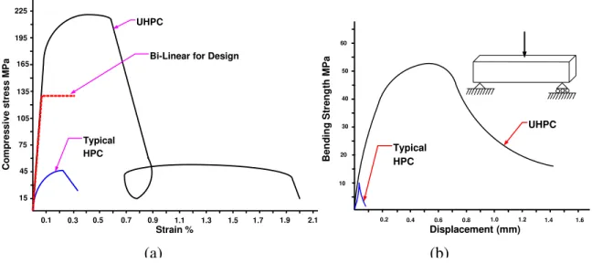
Simply supported slab-on-precast girders bridge is one the most common forms of structural systems used for the construction of highway bridges in North America. There was a considerable growth throughout the last four decades in the use of high strength/high performance concrete (HSC/HPC) in highway bridges. However, the benefits of using HSC/HSC to extend the span length or reduce the weight of simply supported precast girder bridge systems reach a limit at about 50 MPa, beyond which there is only marginal improvement as the governing design criterion is the condition of no cracking at service [1,2]. Ultra high performance concrete (UHPC) represents a major development step over HPC, through the achievement of very high strength and very low permeability. The compressive strength of UHPC varies from 120 to 400 MPa, its tensile strength varies from 8 to 30 MPa, and the modulus of elasticity is in the range of 60 – 100 GPa [3,4]. Figure 1-a and b show a typical stress strain relation and a typical bending strength versus displacement of ultra high performance fiber reinforced concrete with lower-bound mechanical properties compared to a typical high performance concrete. Figure 1-a also shows the conservative bi-linear approximation of the stress strain relation used in design.
A growing number of bridges are being designed and built using UHPC in Europe [5] and United States [6] and opened to traffic recently. However, comprehensive structural evaluation and design methodologies for this type of construction are required. The first UHPC highway bridge [5] was designed and constructed in France and opened to traffic in 2001 with two simply supported spans of 22 m each. At the same time, another UHPC bridge [6] was constructed in Italy with a span of 11.8 m. More recently, a 33.8 m span UHPC bridge was designed and constructed in Iowa and opened to traffic in late 2005 [7]. A general analysis and design approach of concrete slab on precast/prestressed UHPC girders has been proposed [13] and a primary evaluation of the structural performance of this type of bridge compared to typical HPC bridges is presented [14].
The only available design guidelines for UHPC structures are the French recommendations, AFGC-IR-02 [8]. These recommendations provide modifications to the existing French design standards for reinforced and prestressed concrete structures. However, it does not provide detailed design recommendations for highway bridge structures. Hence, there is an urgent need to develop a procedure for the design of UHPC bridges according to the Canadian Highway Bridge Design Code (CHBDC-06) [10] and using the available standard Canadian Prestressed Concrete Institute (CPCI) [9] precast/prestressed I-girder sections. The draft of the Japan Society of Civil Engineers, recommendation for design and construction of UHSFRC structures [14] is released recently, which represents a modified version of the French recommendations.
The objective of this paper is to evaluate the structural efficiency of typical CPCI precast UHPC I-girder bridges compared to that of HPC I-girder bridges in terms of span length capability, maximum feasible girder spacing, and minimum girder size that will yield the minimum number of girders and minimum weight of the entire superstructure.
DESIGN OF SLAB-ON-UHPC GIRDER BRIDGE SUPERSTRUCTURE:
Two simply supported bridge superstructures are considered in this study, a typical cast in place concrete slab on precast/prestressed (PC) HPC Girders Bridge; and a typical cast in place concrete slab on PC UHPC girders. The total width of the bridge including the barrier walls is 12.45 m and its span length is variable. The slab thickness for both bridges is 175 mm, which corresponds to the minimum slab thickness allowed in the Canadian Highway Bridge Design Code. Two standard CPCI precast prestressed girders, CPCI-900 and CPCI-1200 are chosen for the present investigation.
The traffic load and bridge design fulfill all Serviceability and Ultimate Limit States (SLS and ULS) requirements of CHBDC-06. Two types of live loads are applied on the deck surface, the lane loading and a single moving truck. The width of the studied bridge can accommodate two or three design lanes, hence multi-lane loading modification factors of 0.9 and 0.8 are applied for two and three lanes, respectively. For the Ultimate Limit States (ULS), the magnification factors for the dead and traffic loads are 1.2 and 1.7, respectively. The material reduction factors are 0.75 and 0.95 for precast concrete and prestressing steel, respectively. At each section, it is ensured that the factored moment and shear force are less or equal to the factored flexural resistance and shear resistance, respectively.
Design requirements and procedure:
The design of the bridge is done in accordance with CHBDC-06 regarding the live load model and load factors, however, the resistance factors for UHPC at ULS are conservatively adjusted by referring the AFGC-IR-02 recommendations. The iterative design procedure for the UHPC bridge used in this study is illustrated in Fig.2. As indicated in Fig.2, once the initial feasible superstructure design is determined, a refined analysis is performed using a linear elastic finite element model to check its adequacy. At this stage, the detailed stress distribution is examined to identify the zones of maximum stresses to optimize the girder section and prestressing steel area and layout.
Prestressing system for HPC and UHPC girders:
The selected prestressing are low-relaxation strands, size 13, Grade 1860, with nominal diameter of 12.7 mm and nominal area of 98.7 mm2 and tensile strength (fpu) of 1860 MPa. CHBDC-06
limits the minimum effective stress in tendons to 0.45 fpu, the maximum stress at jacking is
limited to 0.78 fpu; the maximum tensile stress at transfer to 0.74 fpu; and the maximum stress at
ultimate to 0.95 fpu The total prestress losses are estimated to be 16.9% of the tendon strength.
The tendons for the HPC and UHPC girders are arranged in straight and conventional deflected strand pattern groups. The straight tendons provide 50% to 60% of the total prestressing steel area, depending on the maximum stresses in the girder. There was no need to debond the strands near supports as the tensile stresses remained below the allowable value.
HPC Bridge girder design:
The HPC used for the girders has a compressive strength of 40 MPa; initial compressive strength of 30 MPa, and a modulus of elasticity of 29.3 GPa. The slab is made of normal concrete with of 30 MPa and a modulus of elasticity of 25.6 GPa. The cracking strength of HPC is ) ( ' c f ) (fci' ) ( ' c f ' 4 .
0 fc . At transfer and during construction, the allowable compression stress is
and the limit for tensile stress is , where
' 6 . 0 fci cri f 5 .
0 fcri is equal to0.4 fci' [10]. In the present study,
the bridge is designed for no cracking at SLS. The deflection of the bridge for superstructure vibration control is checked in accordance to Cl. 3.4.4 of CHBDC-06 [10]. It is found that five CPCI-900 and five CPCI- 1200 can bridge a span of up to 25 and 29 respectively, while five CPCI-1600 girders are required to bridge 45 m span length (Fig. 3). The corresponding girder spacing is 2.5 m and the length of the cantilever slab is 1.225 m on each side. The main properties of all investigated CPCI sections are summarized in Table 1.
UHPC Bridge girder design:
The two smallest CPCI girders, CPCI 900 and CPCI 1200, are selected to investigate their structural efficiency for use with UHPC. It is found that only four girders are needed for the UHPC bridge design (Fig. 3). It is found that only four girders are needed to bridge 45 m span for both girder sizes using the lower bound mechanical properties of UHPC. Figure 2 shows the bridge-superstructure cross section for HPC–CPCI-1600 and UHPC–CPCI-900 girders. The girder spacing for four girders bridge is 3.3 m and the side cantilever slabs of the deck are 1.275 m each. The UHPC used has a compressive strength (f’c) of 175 MPa and a modulus of elasticity
of 64.0 GPa. The slab is made of normal concrete with a compressive strength of 30 MPa and a modulus of elasticity of 25.6 GPa. The allowable tensile strength of UHPC at (SLS) is taken conservatively as '
c
t 0.4 f
f = [13, 14].
At transfer and during construction, the compressive strength is taken as . The allowable compressive stress is . The limit for tensile stress is , where is taken conservatively as MPa fci' =105 ' 6 . 0 fci 0.6fcri fcri ' ci cri 0.4 f
f = . In the present study, the bridge is designed for no cracking at SLS. The deflection of the bridge for superstructure vibration is also checked in accordance with
CHBDC-06. On the other hand, the ultimate compressive strength is given as and the ultimate strain in 0.3% [8, 13].
' 64 . 0 c cu f f =
At each section, it is ensured that the factored moment and shear are less or equal to the factored flexural and shear resistances, respectively. To ensure a ductile failure at ultimate limit state (ULS), the compressive stresses in the concrete and the tensile stresses in the prestressing steel are kept below the ultimate limit values, respectively, while the strain in prestressing steel is well beyond the yield strain.
The ultimate shear strength Vu consists of three major components: (i) the concrete contribution,
Vc; (ii) the shear reinforcement contribution, Vs; and (iii) the prestressing reinforcement
contribution through the effective prestressing force component in the direction of applied shear, Vp. For UHPC, the concrete contribution is calculated using AFGC-IR-02 Cl 7.3,21, which
consists of two components: (a) the concrete contribution, VRc =0.16 fcjb0z, where is the web width and
0
b
z is the effective depth, and (b) the fiber contribution Vf, which is given in [8]. The
shear strength of the UHPC girder is found to be sufficient to resist the applied shear force, however, minimum shear reinforcement should be provided in the critical shear zones to increase the safety against shear failure.
REFINED ANALYSIS USING FINITE ELEMENT METHOD: Three dimensional finite element modeling:
A linear elastic three-dimensional (3-D) finite element model (FEM) is used to determine the stress distribution in all girders that make up the two investigated bridges. This 3-D FEM model enabled a more accurate prediction of the stresses in all girders than the simplified analysis approach of the code used in the initial step (see Figure 2). Both the deck slab and girders are modeled using shell elements, while the prestressing tendons are modeled using cable elements. The prestressing losses, deformations and relaxation are accounted in the model.
Results and discussions:
The FEM results indicate that the maximum stresses are found in the central girders for both HPC and UHPC for the case of two lanes loading. On the other hand, the maximum stresses are found in the external girders for the case of three-lanes loading. In general, the results show that the maximum stresses for the three-lane loading case are less critical than those of the two lane loading case.
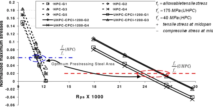
The FEM model enables predicting the stresses in every girder of the bridge and then optimize the prestressing steel ratio, , which represents the ratio of the prestressing steel area to the concrete area of the girder. Figure 4 shows an example of the variations of the stresses at the
ps R
bottom fiber of different girders centerline-cross-section of HPC and UHPC bridges with at SLS. The figures attest that five CPCI-1600 girders are required for the HPC bridge, while only four CPCI-1200 are used for the UHPC. Figure 4 also shows that the most critical girders are the central girder (G3) for the HPC bridge and the internal girder (G2 or G3) for the UHPC bridge. The optimum is found when the critical stresses are equal to the SLS limit for the tensile stresses in concrete. Figure 5 shows that the compressive stresses at ULS in the top fibers of the critical girders identified above are well below the ultimate stress level for both HPC and UHPC girders, while the strain in prestressing steel is well beyond the yield strain. The static deflection at SLS is found to be below (L/400) for CPCI-900 and below (L/500). Figures 3 and 4 demonstrate that the SLS requirements are controlling the design.
ps R
ps R
For the two minimum CPCI girder size, CPCI-900 and CPCI-1200, the maximum span length is 25 m and 29 m for HPC bridge, respectively. Reducing the girder spacing from 5 m to 2.5 m, or in other words, increasing the number of girders from 3 to 5, increase the span length capability of the HPC bridge by 66% and 45% for HPC CPCI-900 and CPCI-1200, respectively. On the other hand, using UHPC for the same girder sizes lead to far longer span length. If the transportation length limit of 45 m is applied for precast girders, 4 girders of either CPCI-900 or CPCI-1200 will be capable to support almost twice the span that similar HPC girders can support. Figure 6 show the variation of the bridge span related to girder spacing (or number of girders) for both HPC and UHPC bridges. It can be concluded from figure 6 that four UHPC girders represent the best choice for the minimum CPCI girder size, which is able to support the maximum feasible precast girder length limit.
A comparison of the results for CPCI 1200 and CPCI 900 shows that the stresses in the CPCI 1200 girder are relatively low and this section represents a conservative choice. On the other hand, all compressive stresses in the CPCI 900 girder are below at SLS and below
at ULS, while the tensile stress at the bottom fiber of the mid-span is at its allowable limit and thus controls the design. Consequently, the prestressing area ratio needed to satisfy the non-cracking requirement is relatively high. A comparison between the two sections indicates that a more efficient section could be developed that falls between CPCI-900 and CPCI 1200.
' c f 45 . 0 0.64fc'
COMPARISON OF MATERIAL CONSUMPTION IN UHPC AND HPC BRIDGES:
The use of UHPC enables a considerable reduction in the concrete volume of up to 49% for the CPCI 1200 and 65% for CPCI 900. The weight of the girders per unit area of the bridge deck are 0.481 tons/m2 for HPC bridge, 0.196 tons/m2 for UHPC –CPCI 900 girders, and 0.288 tons/m2 for UHPC –CPCI 1200 girders. The total weight per unit area of the superstructure, including the deck slab are 0.901 tons/m2 for HPC, 0.616 tons/m2 for UHPC–CPCI 900 girders. Consequently, UHPC results in 32% reduction in the total weight of the superstructure and 59.3% reduction in the girders weight. The prestressing steel area required for CPCI 900 section is 39% higher than that for CPCI 1600, which is only 14% higher than that for the UHPC-CPCI 1200. It is clear that a reduction in the weight of the superstructure will lead to a reduced size of the substructure
(piers and abutments) and foundations and reduced overall cost of the bridge. Furthermore, a reduction in the concrete consumption will have considerable environmental benefits through the reduction of energy consumption and greenhouse gas emission (GHG) associated with the production of cement, extraction and transportation to the construction site of raw materials [12].
CONCLUSIONS:
The use of UHPC in precast/prestressed concrete girders enables a significant increase in the bridge span of the slab-on-girders bridge when compared to conventional HPC bridge girders. UHPC yields a considerable reduction in the number of girders and girder size when compared to HPC bridge of the same span length, and hence results in a significant cut of concrete volume from 49 % to 65 %. On the other hand, the study shows that the reduction of the girder spacing yields a high increase of the span length of the UHPC-bridge, while less improvement is observed for the HPC bridge. It has been shown that four UHPC girders represent the best choice for the minimum CPCI girder size, which is able to support the maximum feasible precast girder length.
A comparison between the two UHPC examined sections shows that an optimum section can be developed that is between CPCI-900 and CPCI 1200 can be achieved by increasing the section modulus. This would improve the girder capacity without adding higher concrete weight. The development of an optimum practical UHPC girder section and hence structurally efficient and cost effective bridge superstructure would lead to a longer life bridges.
REFERENCES:
[1] Lounis, Z., and Cohn, M.Z., “Optimization of Precast Prestressed Bridge Girder Systems”, PCI Journal, V. 38, No. 4, 1993, pp 60-77.
[2] Lounis, Z., and Mirza, M.S., “High Strength Concrete in Spliced Prestressed Concrete Bridge girders.” Proc. of PCI/FHWA Int. Symp. on High Performance Concrete, 1997, pp.39-59.
[3] Acker, P., and Behloul, M., “ Ductal® Technology: A Large Spectrum of Properties, A Wide Range of Application”, Proc. of the Int. Symp. on UHPC Kassel, Germany, 2004, pp.11-23.
[4] Buitelaar, P., “Heavy Reinforced Ultra High Performance Concrete”, Proceedings of the Int. Symp. on UHPC, Kassel, Germany, September 13-15, 2004, pp.25-35.
[5] Hajar, Z., Lecointre, D., Simon, A., and Petitjean, J. “Design and Construction of the World First Ultra-High Performance Concrete Road Bridges”, Proceedings of the Int. Symp. on UHPC, Kassel, Germany, September 13-15, 2004, pp.39-48.
[6] Meda, A., Rosati, G., “Design and Construction of a Bridge in Very High Performance Fiber Reinforced Concrete”, Journal of Bridge Engineering, Vol. 8, No. 5, 2003, pp.281-287. [7] Bierwagen, D., and Abu-Hawash, A., “Ultra High Performance Concrete Highway Bridge”,
Proc. of the 2005 Mid-Continent Transportation Research Symposium, Ames, Iowa, 2005, pp.1-14.
[8] AFGC Groupe de travail BFFUP, “Ultra High Performance Fiber-Reinforced Concretes: Interim Recommendations”, Scientific and Technical Committee, Association Française de Genie Civil, 2002.
[9] Canadian Prestressed Concrete Institute, “Design Manual, Precast and Prestressed Concrete”, Third Edition, 1996.
[10] Canadian Standards Association, CAN/CSA-S6-06, “ Canadian Highway Bridge Design Code”, 2006.
[11] U.S. Department of Transportation, Federal Highway Administration, “ Structural Behavior of UHPC Prestressed I-Girders”, Publication No. FHWA-HRT-06-115, 2006.
[12]Daigle, L., and Lounis, Z., “Life Cycle Cost Analysis of HPC Bridges Considering their Environmental Impact”, Proc. of INFRA 2006, Quebec City, pp. 1-17.
[13] Almansour,H, Lounis, Z., “ Innovative Precast Bridge Superstructure Using Ultra High Performance Concrete Girders“, Proc. of PCI 53rd National Bridge Conference, 2007. [14] Japan Society of Civil Engineers, “ Recommendation for Design and Construction of Ultra
High Strength Fiber Reinforced Concrete Structures (Draft)”, JSCE Guidelines for Concrete, No. 9., September, 2006.
CPCI Girder A (m2) I (m4) St (m3) Sb (m3)
900 0.218 0.0193 0.0384 0.0486
1200 0.320 0.0539 0.0800 0.1023
1600 0.499 0.1747 0.2166 0.2202
A: cross sectional area, I : moment of inertia, St and Sb: section
modulus with regard to top and bottom fibers, respectively
0.1 0.3 0.5 0.7 0.9 1.1 1.3 1.5 1.7 1.9 2.1 15 45 75 105 135 165 195 225 C o m p re ssi ve st re s s MP a Strain % UHPC Typical HPC
Bi-Linear for Design
0.2 0.4 0.6 0.8 1.0 1.2 1.4 1.6 10 20 30 40 50 60 B e n d in g S tr e ng th MP a Displacement (mm) UHPC Typical HPC (a) (b)
Figure 1 Typical UHPC mechanical properties compared to HPC (a) Stress-Strain relation, (b) Bending strength
Initial UHPC / HPC Bridge Superstructure Section
Simplified Analysis and Design (CAN/CSA-S6-06 & AFGC-IR-02)
Initial Design Adequacy
Check
Refined Analysis using Finite Element Model
Design Check Change Prestressing
Steel Area and/or Girder size and/or
No of Girders Yes No Yes No Final Bridge Design Change Prestressing
Steel Area and/or Girder Size
G1 G2 G3 G4 G5
1.225 m 2.5 m 2.5 m 2.5 m 2.5 m 1.225 m
UHPC Bridge: 4- CPCI-900 Girders
G1 G2 G3 G4
1.23 m 3.33 m 3.33 m 3.33 m 1.23 m
HPC Bridge: 5- CPCI-1600 Girders
Figure 3 Slab-on Precast/Prestressed Girders Bridge, 45 m Span
-0 .0 6 -0 .0 4 -0 .0 2 0 0 .0 2 0 .0 4 0 .0 6 0 .0 8 0 .1 0 .1 2 0 .1 4 0 .1 6 0 .1 8 0 .2 9 1 2 1 5 1 8 2 1 2 4 2 7 3 Rp s X 1 0 0 0
Normalized maximum stresses 0
H P C -G 1 H P C -G 2 H P C -G 3 H P C -G 4 H P C -G 5 U H P C -C P C I-1 2 0 0 -G 1 U H P C -C P C I-1 2 0 0 -G 2 U H P C -C P C I-1 2 0 0 -G 3 U H P C -C P C I-1 2 0 0 -G 4 O p tim u m P re s tre s s in g S te e l A re a ) ( ' HPC f f c t ) ( ' UHPC f f c t
-0 .4 5 -0 .4 -0 .3 5 -0 .3 -0 .2 5 -0 .2 -0 .1 5 -0 .1 -0 .0 5 0 0 .0 5 9 1 2 1 5 1 8 2 1 2 4 2 7 Rp s X 1 0 0 0 Normaliz ed Maximum S tresses 3 0 H P C -G 1 H P C -G 2 H P C -G 3 H P C -G 4 H P C -G 5 U H P C -C P C I-1 2 0 0 -T & B -G 1
U H P C -C P C I-1 2 0 0 -T & B -G 2 U H P C -C P C I-1 2 0 0 -T & B -G 3
U H P C -C P C I-1 2 0 0 -T & B -G 4
Figure 5 Variation of maximum ULS stresses with prestressing steel ratio for all girders
0 5 10 15 20 25 30 35 40 45 2 2.5 3 3.5 4 4.5 5 Girder spacing (m)
Span Length (m) HPC- CPCI 900
UHPC- CPCI 900 UHPC- CPCI 1200 HPC- CPCI 1200 G1 G2 G3 1.225 m 5 m 5 m 1.225 m G1 G2 G3 G4 1.225 m 3.333 m 3.333 m 3.333 m 1.225 m G1 G2 G3 G4 1.225 m 2.5 m 2.5 m 2.5 m 2.5 m 1.225 m G5 UHPC- CPCI 900 45 m Span
HPC- CPCI 900 25 m Span
Figure 6 Comparison of the Slab-on-Girders Bridge span length for different girder spacing
Innovative Design of Precast/Prestressed Girder Bridge
Superstructures using Ultra High Performance Concrete
OBJECTIVES:
Develop innovative bridge superstructures using precast construction and HPC/UHPC materials Evaluate performance in terms structural efficiency, span length capability, materials consumption, service life, speed of construction and life cycle cost
Husham Almansour and Zoubir Lounis
Urban Infrastructure Research Program
UHPC Properties
Very high compressive, tensile & bending strengths High modulus and high fatigue resistance
Very low permeability
Initial UHPC / HPC Bridge Superstructure Section
Simplified Analysis and Design (CAN/CSA-S6-06 & AFGC-IR-02)
Initial Design Adequacy
Check
Refined Analysis using Finite Element Model
Design Check Change No of Girders
and/or Girder size and/or Prestressing Steel Area Yes No Yes No Final Bridge Design Change Girder Size
and/or Prestressing Steel Area
Benefits of UHPC vs. HPC
Fewer number of girder lines Longer spans
Lower superstructure weight Lighter substructure
Expected longer service life Expected lower life cycle cost
Analysis & Design of UHPC Bridge Superstructures
0 5 10 15 20 25 30 35 40 45 S pa n Le ngt h ( m ) HPC- CPCI 900 UHPC- CPCI 900 UHPC- CPCI 1200 HPC- CPCI 1200 G1 G2 G3 1.225 m 5 m 5 m 1.225 m G1 G2 G3 G4 1.225 m 3.333 m 3.333 m 3.333 m 1.225 m G1 G2 G3 G4 1.225 m 2.5 m 2.5 m 2.5 m 2.5 m 1.225 m G5
Span Limit (transportation) = 45 m
Max Span = 25 m 0.2 0.4 0.6 0.8 1.0 1.2 1.4 1.6 10 20 30 40 50 60 B en d in g S tr ess MP a Displacement (mm) UHPC Typical HPC G1 G2 G3 G4 G5 1.225 m 2.5 m 2.5 m 2.5 m 2.5 m 1.225 m
UHPC Bridge: 4 – CPCI 900 Girders
G1 G2 G3 G4 1.23 m 3.33 m 3.33 m 3.33 m 1.23 m 45 m span 0.1 0.3 0.5 0.7 0.9 1.1 1.3 1.5 1.7 1.9 2.1 15 45 75 105 135 165 195 225 Co m p re s s iv e st re ss M P a Strain % UHPC Typical HPC
![Table 1 Properties of Investigated Standard CPCI I-Sections [9]](https://thumb-eu.123doks.com/thumbv2/123doknet/14162791.473474/11.918.111.792.778.920/table-properties-investigated-standard-cpci-i-sections.webp)