Publisher’s version / Version de l'éditeur:
Vous avez des questions? Nous pouvons vous aider. Pour communiquer directement avec un auteur, consultez la
première page de la revue dans laquelle son article a été publié afin de trouver ses coordonnées. Si vous n’arrivez pas à les repérer, communiquez avec nous à PublicationsArchive-ArchivesPublications@nrc-cnrc.gc.ca.
Questions? Contact the NRC Publications Archive team at
PublicationsArchive-ArchivesPublications@nrc-cnrc.gc.ca. If you wish to email the authors directly, please see the first page of the publication for their contact information.
https://publications-cnrc.canada.ca/fra/droits
L’accès à ce site Web et l’utilisation de son contenu sont assujettis aux conditions présentées dans le site
LISEZ CES CONDITIONS ATTENTIVEMENT AVANT D’UTILISER CE SITE WEB.
Internal Report (National Research Council of Canada. Institute for Research in Construction), 1994-11
READ THESE TERMS AND CONDITIONS CAREFULLY BEFORE USING THIS WEBSITE.
https://nrc-publications.canada.ca/eng/copyright
NRC Publications Archive Record / Notice des Archives des publications du CNRC :
https://nrc-publications.canada.ca/eng/view/object/?id=344cb220-56c3-420a-9e94-66b6c66849cc https://publications-cnrc.canada.ca/fra/voir/objet/?id=344cb220-56c3-420a-9e94-66b6c66849cc
NRC Publications Archive
Archives des publications du CNRC
For the publisher’s version, please access the DOI link below./ Pour consulter la version de l’éditeur, utilisez le lien DOI ci-dessous.
https://doi.org/10.4224/20375784
Access and use of this website and the material on it are subject to the Terms and Conditions set forth at
Temperature Measurements in Fire Resistance Tests on Small-Scale
Wall Assemblies of Different Cavity Depths, Stud Types and
Asymmetrical Installations of Gypsum Board
National Research Conseil national
i*I
Council Canada de recherches Canada lnstttute for lnst~tut deResearch ~n recherche en
Constructton constructton
HC-CIWC
Temperature Measurements in Fire
Resistance Tests on Small-Scale
Wall Assemblies of Different Cavity
Depths, Stud n p e s and Asymmetrical
lnstallations of Gypsum Board
by M.A. Sultan, J.W. MacLaur~n, E.M.A. Denharn and D.W. Morwick
Internal Report No. 670
Date of issue: November 1994
CISTI/ICIST NRC/CNRc Internal report :
institute
IRC Ser --Bev Creigkton
Received on: 12-15-94 ANALYsE
Internal report : Institute
for Researck in Construction ~ N A L Y Z E D
Canada
Th~s 1s an Internal report of the Institute for Research In Construction Although not intended for general dtstrtbut~on, it may be c~ted as a reference in other publ~catlons
Canad!!
ACKNOWLEDGMENTS
This research is a Joint Research Project among the following partners. The
National Research Council Canada W C C ) appreciates the participation of these partners
in research, both in terms of their financial contributions and in terms of their technical
contributions through the Project Steering Committee.
Canada Mortgage and Housing Corporation
Canadian Home Builders Association
Fiberglas Canada Inc.
Roxul Inc.
Cellulose Insulation Manufacturers Association of Canada
Gypsum Manufacturers of Canada
Forintek Canada Corporation
Canadian Sheet Steel Building Institute
Institute for Research in Construction
'I'E\IPER.-ZTURE RIk:,\SUIIEMENI'S IN FIRE RESISTl\NCE TESTS ON SRIAI.1,-SCALE WA1,I. ASS1~31111,1b:S O F DIFFI<l<I~R'l' CAYI'I'Y L)EPTlfS, STL1) TSPIIS AN11 A S Y ~ 1 ~ 1 1 ~ ~ l ' I 1 I C A I . ISS'CAI.I.~\'L'IONS
O F
<;YPSU3I BOARDABSTRACT
This report presents the temperature nleasurements from fire resistance tests conducted at the National Fire Laboratory (NFL) on small-scale, non-insulated, steel and wood stud, gypsum board protected assemblies. GYPSUIII board arrangements studied were 1x1 (one layer of board on both the exposed and unexposed sides), 1x2 (one layer of board on the exposed side and two layers of board on the unexposed side), 2x1 (Two layers of board on the exposed side and one layer on the unexposed side) and 2x2 (two layers of board on both the exposed and ~lnexposed sides). The effects of using different cavity depths, stud types and asy~nmetricnl installations of gypsum board on the fire resistance in small-scale fire tests were studied. The average temperature distribution on the unexposed surface as well as on the inner-surfaces are presented.
TER1PI~:llhTIJIIE h l l ~ ~ A S ~ I < I ~ \ l l ~ ~ S S I ' S IN I:IHE HI.:SIS'TAKCE TESTS ON SRl,\I.I.-SCAI.1' WALL ASSIIRIIII.11IS 01: L)IFI.'l<KEN'T CA\'ITY DEPTHS. S'l.1'1) 'TYPES ASI) ASYfil\ll*:'I'I<ICc'\II 1NS'TAI.I.AI'IOSS O F (;YPSlJhl HOARD
1 INTRODUCTION
A number of recent changes to the 1990 edition of tlie National Building Code of Canada (NBCC) and to CANICSA-A82.27-M91 "Gypsu~ii Board-Building Materials and Products" may have an effect on the fire performance of insulated and non-insulated gypsum board assemblies. One of the n~:~jor issues is that the requirement for weight per unit area for gypsurn board products has been removed. As well, there have been changes in the NBCC to increase the sound transmission ratings (STC) between dwelling units. These changes may have an impact on the fire resistance of both wall and floor assemblies referenced 111 Parts 3 and 9 of tlie NBCC, as well as tlie cclculation methods in Chapter 2
of tlie Supplelilent to tlie NBCC.
As a result of these changes, a Joint Research Project between IRCNRCC and 8 industry partners has been conducted with the primary objective of determining the impact that the various changes to tlie code and standard may have had on the fire resistance ratings of insulated and non-insulated gypsitin board assemblies. A number of fitll-and small-scale tests have been conducted to st~tdy the effects of different parameters, such as the installation of resilient channels, i~is~tlation in the wall cavity, gypsumboard types and symmetric~~l and asymmetrical gypsumhoard installations.
This report presents the results of sonie of those tire tests conducted at the Nation;tl Fire Laboratory, National Research Council Canada to deterniinr the effects of using different cavity depths, s t ~ ~ d types 2nd asy~iimetrical installations of gypsum board on the fire performa~lce of the assemblies. Other reports will deal with other issues in this project.
2 DESCRIPTION
OF
TEST ASSEMBLIESThe small-scale test asse~nbly furnace set-up is shown in Figure 1.
Nine assemblies were constructed 9 14 mill high by 914 111111 wide with various
depths depending on the nu~iiher of layers of g y p s ~ ~ ~ i i board. The specific dimensions of each asse~nbly are give11 in Figures 2 to 10.
2.2 Materials
2.2.1 Gypsum Board
Type X gypsum board confor~ning to the req~~ireinents of CANICSA-A82.27-M91 [I] was used. The 12.7 111111 thick Type X gypsu~n boxd had a masslunit area of
7.83 kg/tii2.
2.2.2 Framing Materials
The steel studs used were light C sections 90 inn1 wide by 30 mlii deep by 0.6 mm thick, manufa~ctured in accordance with CAN/CGSB-7.1 [ 2 ] . The wood framing members were nominal 2x4's (38 t i i ~ i i thick by 89 mm deep) and co~iformed to CSA 0141-1970 [3].
2.3 Fabrication
The s~liall-scale assemblies were constructed using similar construction practices to those eniployed for fi~ll-scale fire test assemblies. All small-scale tests were non-load bearing.
2.3.1 Wood Stud Assemblies
The wood studs ~ ~ s e d were 38 In111 by 89 mni (SPF No. I and No. 2, S-Dry, QLMA Mill Grade 149) and spaced at 400 111111 O.C. To ~ u a k e LIP the required furnace
width of 9 14 by 914 mlii, an additional stud was added to each end. The top and bottom plates were then added to co~nplcte the box asseiiihly construction.
For single layer construction, with wood s t ~ ~ d s spaced at 400 mrn O.C., one layer of 12.7 mm thick Type X gyps~~nlboitrd was attached to the wood studs with Type S drywall screws, 4 1 111111 long and spaced at 400 In111 O.C. along the edges and in the Geld
of gypsumhoard. The screw heads were covered with joint compound. Screw locations and gypsumbor~rd joints are shown in Figc~res I I and 12 [4]. The board joints were finished with fibre rape and joint compound.
In the d o ~ ~ b l e g y p s ~ ~ ~ i i li~yer construction with wood studs spaced at 400 mrn O.C., two layers 12.7 m1ii th~ck Type
X
gypsum were applied: base and face layers. The base layer was attached to the wood studs, with Type S drywall screws 41 mm long spaced at 600 111111 O.C. along the edges and in the field of the bonrd. Screw locations andgypsumboard joints are shown in F i g ~ ~ r e s 12 and 13 [4]. The face layer was attached to both the base layer and the studs with screws 5 1 111111 long, spaced at 400 mrn O.C.. Screw
heads on both the exposed and i~nexposect faces were covered with joint compound. The board joints were taped nnrl covered with joint compound.
2.3.2 Steel Stud Assemblies
The steel s t ~ ~ d s used were light C sections 90 mm by 30 lnni by 0.6 mm spaced at 600 mm O.C. In order to complete the box asse~iibly, two end studs were added. Header and footer studs were also atlded. The end sti~tls hat1 ;I 12.7 mlii g y p s ~ ~ m board facing
screwed into the web (see Figure 3).
For single layer construction, one layer of 12.7 nim thick Type X gypsuinboard was attached to the steel htuds with Type S drywall screws, 25 mm long and spaced at 300
m m
O.C. along the board edges and in the field of the bonrd. The screw heads were covered with joint coilipound. Screw locutions and gy[?vumhoard joints are shown in Figures 14 to 16 [4]. The b a r d joints were finished w ~ t h fibre tape and joint compound.In the double gypsu~ii layer construction, two layers of 12.7 nim thick Type X
gypsumboard were applied: base and face layers. The base layer was attached to the steel studs with Type S drywall screws 25 1ii11i long and spaced at 300 lnln O.C. along the
edges and spaced at 600 nlnl O.C. in the field of the board. The face layer was attached to both the base layer and the studs with screws 41 nim long, spaced at 300 mm O.C. along the board edges and in the field of the hoard. Screw heads on both the exposed and unexposed faces were covered with joint C O I I I P O U I ~ ~ . Gypsu~liboard joints were taped and
covered with joint compound. Screw locations and gypsumboard joints are shown in Figures 15 to 17 [4].
2.4 Instrunlentation
Type K (20 gauge) chromel-alumel thermocouples, with a thickness of 0.91 mm, were used for ~iieasuring temperatures at a nu~iiher of locations throughout an assembly. Inside the cavities, the ther~i~ocouples were attached to 2 wire hangers, installed midway between the st~lds and at niid depth of the studs at distiunces of 114 and 314 of the height of the wall. By providing tension to the hanger wire, the thernioco~~ples were positioned flush with the stlrface of the wallboard.
Ther~iiocouples located on studlwallbo;~~-d faces and those located between wallboard layers were taped into position and then tlie wallboard was screwed to the
S ~ L I ~ S .
In wood s t ~ ~ d asseniblies, iu 11~11iiber of s~nall holes, 12.7 lnln dianieter, were drilled
through the wood studs to allow the ther~nocouple wiring to exit the assembly. The ther~noco~~ple loc:ktions are shown for each assembly in Figures 2 to 10.
3 TEST APPARATUS
The tests were carried out by exposing the asse~nblies to heat in a propane-fueled, fire brick lined vertical furnace with an 810 by 810 m m opening. The assemblies were sealed at the edges against the fi~rnace with ceramic fibre blanket. The furnace
telnperature was ~neasured by two 20 gauge shielded thennocouples, located near the vertical centreline of the furnace and 300 mm fro111 the exposed surface of the assembly. The average of these two temperatures was ~lsetl to control the furnace temperature.
4 TEST CONDITIONS AND PROCISDUKES 4.1 Fire Exposure
The ambient temperature at the start of each test was approximately 22°C. During the test, the wall asse~iibly was exposed to heating on the exposed side, in such a way that tlie ;werage temperilture in the furnace followed, as closely as possible, the
CANIULC-S 101-MX9 [5] standard temperat~tre-time curve.
4.2 Failure Criteria
The failure criteria for the s~iiall-scale tests were derived fro111
CANIULC-S I0 I-M89 [ 5 ] . The assembly was considered to have failed if a single point ther~noco~lple temperature reading on the ~lnexposed face rose 180°C or if the average
temperature of the 5 thermocouples readings under the insulated pads on the unexposed face (see F i g ~ ~ r e 2 I) rose 140°C above the ambient te~nperuture or if the]-e was passage of flame or gasses hot enough to ignite cotton waste. The tests were run beyond the failure teliiperature referred to above in order to provide additional performance data.
4.3 Recording of Results
The f ~ ~ r n a c e and wall assenlbly temperatures were recorded at 1 minute intervals ~lsing LABTECH NOTEBOOK data acquisition software end a Fluke Helios-I data acq~i~sition system.
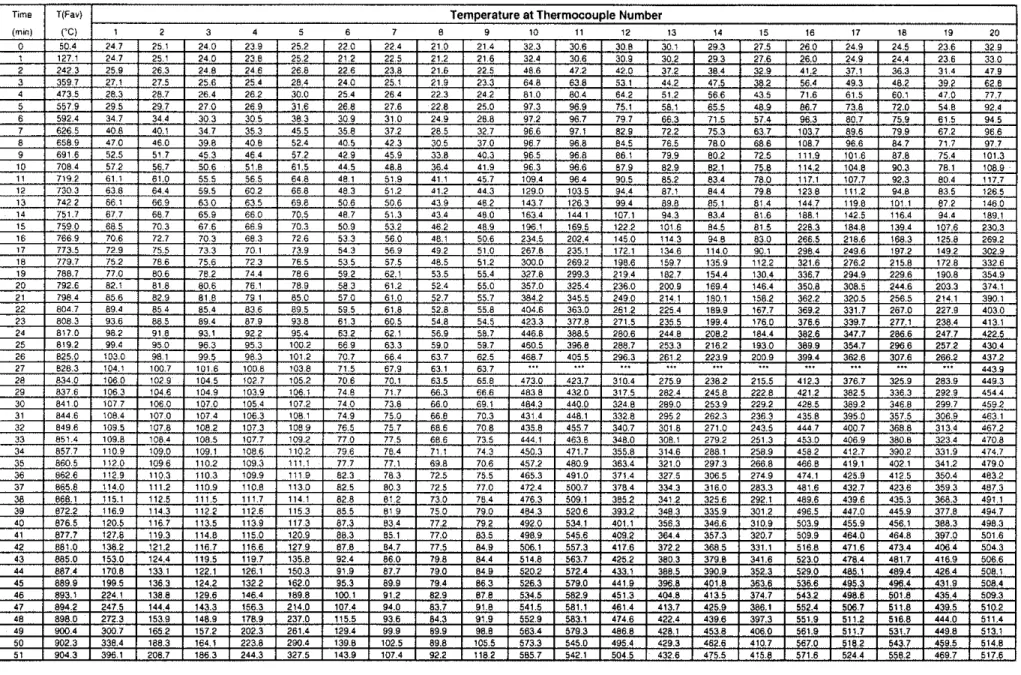
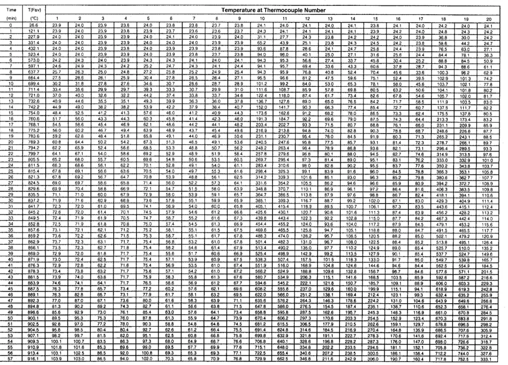
Individ~~al thermocouple values and average furnace tetiiperature values as well as the average surface teliipernture values for the 9 asse~iihlies are listed in Tables 1 to 17.
The average surfitce and inter-surface tempen~tui-e distributions during the test for the 9 assemblies are plotted in Figures 19 to 27. Detailed tetiiper;~ture distributions for all five thermoco~~ples on tlie ullexposed surface for the 9 assemblies are also plotted in Fig~ires I9 to 27.
The res~ilts of the 9 small-scale fire tests conducted on non-insulated assemblies are s~iili~liarized in Tahle 18 in which the point and average failure times are given for each assembly. Specific information for each assembly is also given.
Effect of Cavity Deptll on the fire Perforlliailce of Small-Scale Wall Assernhlies Two different cavity depths of a ~ioii-iiisulnted, asym~netrical gypsu~il board installation 1x2 were studied: 90 m111 and 65 mill (steel studs) acid 89 Inln and 65 mm (wood studs). Tests S-10 and S-39 were carried out to investigate the effect of cavity depth on the fire perforiii;~nce of small-scale steel s t ~ ~ d asseii1blies. The temperature failure critel-ion was reached at 86 inin for Test S-10 and at 88 min for Test S-39.
Tests S-3 I and S-40 were cond~icted to investigate the salile effect using wood
S ~ L I ~ ;~ssemhlies. Tlie teiiipe~xture frtilure criterion was reached at 96 inin for Test S-31
and at 86 min fol- Test S-40. These results (see Figure 28) showed that, for non-insulated asymmetricnl gyp.;um board 1x2 sl~iall-scale assemblies, the cavity size does not materially affect the fire pertormniice of steel stud assemblies hut slightly affects the fire performance of wood stud i~sse~iihlies.
Effect of Stud Type on the Fire Perforllla~ice of Small-Scale Wall Assemblies Two different sttid types, steel and wood, in non-insulated 1x1 gypsum board arr;lngement assemblies were studied. Test S-08 (wood) and S-09 (steel) were carried out to investigate the effect of st~td type on the fire performa~ice of s~ilali scale assemblies. The teniperature fi~ilui-e criterion was reached at 46 inin for Test S-08 and at 46 min for test S-09.
Tests 5-3 1 (wood) and S-10 (steel) were cond~icted to investigate the same effect ~ ~ s i i i g asyliliiietrici~l ~ Y ~ S L I I I I bo;~rd ilistalli~tioii (I x2) assemblies. The teliiperature failure
Tests S-36 (wood) and S- I2 (steel) were also cond~~cted to investigate the effect of stud type on the fire performance of 2x2 small-scale assemblies. The temperature failure criterion was reached at 142 min for Test S-36 and at 129 min for Test S-12.
These results showed (see Figure 29) that for lx I non-insulated assemblies, the stud type does not affect the fife perforlllance of the i~ssemblies. In 1x2 and 2x2 non-insulated assernhlies, the wood sti~ds provided a slightly better fire pel-forniance compared to steel studs.
Effect of Different Asynimetrical Installations of Gypsunl Board on the Fire Performance of Small-Scale Assemblies
Two different non-insulated, asy~iimetrical gypsulii hoard insti~liations were studied. Tests S-10 and S-l 1 were carried out to investigate the effect of different asy~nrnetrical
installations of gypsu111 hoard (1x2 vs 2x1) on the fire perfomlance of small scale steel stud asse~i~blies. The temperature fiiilure criterion was reached at 86 min for Test S-10 and at 85 min for Test S- l I . These results (see Figure 30) showed that different non- insulated symmetrical g y p s ~ ~ m board installations 111 small-scale asse~nhlies do not affect
the fire perforin;lnce of the itsse~iihlies. It I ~ I L I S ~ be noted that these are non loadbearing
1. CANICSA-A82.27-M9 1, Gypsum Board B ~ ~ i l d i n g Materials and Products, Canadian Standards Association, Rexdale, Ontario, I99 1.
2. CANICGSB-7.1-M86, Cold Formed Steel Framing Components, Canadian General Standards Board, Ottawa, Ontario, 1986.
3. CSA 0141-1970, Softwood Lumber, Canadian Standards Association, Rexdale, Ontario, 1970.
4. CANICSA-A82.3 1-M91, Gypsu~ii Board Application, Canadian Standards Association, Rexdale, Ontario, 1991.
5 . CANIULC-S I0 I-M89, Standard Methods of Fire Endurance Tests of Building Construction and Materials, Underwriters Laboratories of Canada, Scarborough, Ontario, 1989.
Table 6. Average Tetilperatures Measured in Assembly S-10, Steel Stud, 1x2 Gypsum Layers, No Insulation
Legend: E L
-
Base Layer, FL-
Face Layer. Cav. -Cavity. SStd. -Steel Stud, Av-
Average, Exp. -Exposed Side, UnExp.-
Unexposed SideTable 8. Average Temperatures Measured in Assembly S-I 1, Steel Stud, 2x1 Gypsum Layers, No Insulation
Legend: BL
.
Base Layer. FL. Face Layer, Cav.-
Cavity, Std. -Stud, Av -Average, Exp.-
Exposed Side, UnExp.-
Unexposed SideBUFL (Erp.)
I
BUSSld. (Exp.1I
8ucau. (Erp.)I
Mid SStd.I
8UCav. (UnExp.)1
BLISld. (UnEip.)I
UnExp.I
-
4 5 1 887 5 1 6 1 1 3 I 260 4 1 222 3 1 1641 I 186 3 I 1182 I 74 1
Table 8. Average Temperatures Measured in Assembly S-1 I , Steel Stud, 2x1 Gypsum Layers, No Insulation (Cont.) Legend: EL
-
Base Layer, FL-
Face Layer. Cav.-
Cavity, Std.-
Stud. Av-
Average, Exp. -Exposed Side, UnExp.-
Unexposed SideTable 10. Average Temperatures Measured in Assembly S-12, Steel Stud, 2x2 Gypsum Layers, No Insulation
Legend: BL
-
Base Layer, FL-
Face Layer. Cav.-
Cavity, SStd.-
Steel Stud. Av-
Average, Exp.-
Exposed Side, UnExp.-
Unexposed SideTable 12. Average Temperatures Measured in Assembly S-31, Wood Stud, 1x2 Gypsurn Layers, No Insulation, Resilient Channel
Legend: BL
-
Base Layer. FL. Face Layer, Cav. -Cavity, Std. -Stud, Av-
Average, Exp. -Exposed Side. UnExp.-
Unexposed SideTable 12. Average Temperatures Measured in Assembly S-3 1, Wood Stud, 1x2 Gypsum Layers, No Insulation, Resilient Channel (Cont.) Legend: E L
-
Base Layer. FL-
Face Layer, Cav. -Cavity. Std.-
S t u d , Av-
Average, Exp.-
Exposed Side, UnExp.-
Unexposed SideTable 14. Average Temperatures Measured in Assembly S-36, Steel Stud, 1x2 Gypsum Layers, No Insulation (Cont.)
Legend: BL
-
Base Layer, FL-
Face Layer, Cav.-
Cavlty, Std. -Stud, Av -Average, Exp.-
Exposed Slde, UnExp.-
Unexposed SideTable 14. Average Temperatures Measured in Assembly S - 3 6 , Steel S t u d , 1x2 Gypsum L a y e r s , No Insulation ( C o n t . ) Legend: BL
-
Base Layer, FL - Face Layer, Cav.-
Cavity, Std. -Stud, Av-
Average, Exp.-
Exposed Side, UnExp.-
Unexposed SideTable 16. Average Temperatures Measured in Assembly S-39, Steel Stud, 1x2 Gypsum Layers, No Insulation (Cont.) Legend: BL
-
Base Layer, FL-
Face Layer, Cav.-
Cavity, SStd.-
Steel Stud, Av-
Average, Exp.-
Exposed Side, UnExp.-
Unexposed SideTable 18. Average Temperatures Measured in Assembly S-40, Wood St~ld, 1x2 Gypsum Layers, No Insulation
Legend: BL
-
Base Layer, FL-
Face Layer, Cav.-
Cavity, Std.-
Stud, Av-
Average, Exp.-
Exposed Side, UnExp.. Unexposed SideTable
19.Small-Scale Assembly Parameters and Fire Test Results
X
-
Type X Gypsum Board(7.83 kg/rn2) E-
Exposed SideFire
Exposed Side
914 rnrn
Unexposed Side
IPIMrnrnl
Drawing Not To Scale
682 rnrn
232 rnrn
I
Fire Exposed Side
Gypsum Board Facing I I I7A
18 90 rnrn steel studs---/L
t!P
Unexposed Side
Dmwing Not To Scale
Fire
Exposed Side
$8 1B-
I 20 21 Steel StudsJ
-
1. aa a3 *7Unexposed Side
k
-
600 mm-1
Drawing Not To Scale
Fire
Exposed Side
,$, 14 13 11 z l n 90 rnrn Steel Studs 1s 17 n 22 s 31Unexposed Side
p
-
600 rnrn9
914 rnrnDrawing Not To Scale
682 rnrn
232 rnrn
1
Fire
Exposed Side
I 0 m 11-
11 m za-
-
?l 9 Y 31 2431
it
Steel StudsJ
-
m I. I#::
i!
Unexposed Side
h-
600 rnrn---of
Figure 6 . Thermocouple Locations
in
Small-Scale Test 5-1 2r
914 rnrn
L,
f~
--I
g14 rnrn
4
Drawing Not To Scale
I I
I
I
I
I
I
I
I
I
I
I
I
I
I
v4.L;;I
I
::
I
I
I
I
I
I
I
II
I
I
I
I
I
I
I
I
I
1
15. 'II
I
1
::
".
I
I
laI
I
I
I
I
I
I
I
I I7
682 rnrnqmrn
1
Fire
Exposed Side
Gypsum Board Facing Resilient Channel/
Unexposed Side
400 rnrn4
I
I
-_
-
- T 2:
=
57 "lmI l l
7
II
I
I
II
l l
I
3II I
I
I
I I
I
I
I
914 rnm---+t
---
682 rnrnII I
Ib.yntQlalI
I
I
11
232 rnm- - -
Dmwing not to scale
Fire Exposed Side
89 rnrn
m n
f
Unexposed Side
Dmwinq Not To Scale 914 rnrn
Figure 8. Thermocouple Locations in Small-Scale Test 5-36
-1-1-
-
-- -
r - - - - -1-II I
I I
I ll
I1
I
kzI
I I1
I1 I
-8
m la+$*II I
l I
-1
II I
I I
II I
I I
I
II
11
1
llJ
I
11
682 rnrn1 1
I
18@
2%II I
-11 m n l1T
I
'
"
II I
I
I
J
- - -
I
I I
Fire Exposed Side
r
Gypsum FacingUnexposed Side
I
I
I
I
I
I
I
I
I
I
I
I
I
I
I
I
I
I
I
I
I
I
I
I
I
I
I
I
914 mrnI
I
I
I
I
I
I
I
II
I
I
I
I
II
I
I
I
I
I
I
682 rnmI
11,.;:
IliI
I
I
I
I
I
I
I
I
I
I
I
Drowing Not To Scale
Fire Exposed Side
Unexposed Side
I
I
I II
II I
I ll
II I
I I
I
I
I
1II I
914 rnrnI
I
II I
I
I
I
I I
II I
I I
I
::
I ll
682 rnmII I
II I
I
I
II I
I I
-4
t z
9 w rnrn-1
Drawing Not To Scole
Fire Exposed Side 400 mrn
Unexposed Side
Gypsum Board Joint
914 mm 400 mm
400 mm
914 mrn
4
914 m m--A
(i) Fire Exposed Side
(ii) Unexposed Side
Drowing not to scale
Figure 11. Screw Locations For Wood Stud, 1x1 Gypsum Board Layers,
Fire Exposed Side
4
400 rnrnto-
Base Loyer
W
W
Face Layer Unexposed Side
(a) Base Layer (a) Base Layer
Gypsum Board Joint
914 mm
400 rnm
b
(b) Face Layer
-4
400 m m Gypsum Board Joint /k)---
914 rnm4
(i)
Fire Exposed Side
(ii) Unexposed Side
Drawing not to scale
Figure 12. Screw Locations For Wood Stud, 1x2 Gypsum Board Layers,
Fire Exposed Side
4
400 mrnk
bw
A
89 mm Base Layer d-
7 Face Layer1
4
400 mrnk+
7
Unexposed Side(a) Base Layer (a) Base Layer
4
400 mm4
400 rnm k r G ~ ~ s u m Board Jointrnm
(b) Face Layer
Joint
(i) Fire Exposed Side
(b) Face Layer
Drawing not to scale
400 mrn
6
91 4 mm----4
(ii)
Unexposed Side
Figure 13. Screw Locations For Wood Stud, 2x2 Gypsum Board Layers,
Fire Exposed Side
k-~
600 mrn4
-
Unexposed Side I x #I-\ .I cnn ,, I' ' I .I I u v v ,,*!,, 9 1 4 rnrn Gypsum Boord I Gypsum Board Joint'1
1
1
9 1 4 mrn4
6
9 1 4 mm4
'f
(i)
Fire Exposed Side
(ii)
Unexposed Side
Drawing not to scole
Figure 14. Screw Locations For Steel Stud, 1x1 Gypsum Board Layers,
Fire Exposed Side 600 rnrn
1
-Base Layer
C C
y
Face Layer Unexposed Side
(a) Base Layer
-o(
600 rnrnb-
914 rnrn4
(a) Base Loyer
--91
600 rnrn irn Jk-
914 rnrn4
(b) Face Loyer4
600 rnrn Gypsurn Board Joint(i)
Fire Exposed Side
(ii) Unexposed Side
Drawing not to scale
Figure 15. Screw Locations For Steel Stud, 1x2 Gypsum Board Layers,
Fire Exposed Side
Face Layer 600 rnrn
Base Layer
L
Unexposed Side
(0) Bose Layer (a) Base Layer
600 mrn
-4
600 rnrn 914 mrn Gypsum Board Joint (b) Face Layer 600 rnrn/-=-
914 mrn 600 rnrn u r n Board Joint 914 rnrn-4
(i)
Fire Exposed Side
(ii)
Unexposed Side
Drawing not to scale
Figure 16. Screw Locations For Steel Stud, 2x1 Gypsum Board Layers,
Fire Exposed Side 600 rnm
C
[
Bose Loyer
Face Layer Unexposed Side
(a) Base Layer (a) Base Layer
914 mrn
L
.
, G v ~ s u m Board. .
1
Joint (b) Foce Layer 600 rnm\
Gypsum Board Joint (b) Face Loyer 600 m m(i)
Fire Exposed Side
(ii)
Unexposed Side
Drawing not to scole
Figure 17.
Screw
L o c a t i o n sFor
Steel S t u d , 2x2 Gypsum Board Layers,Thermocouple Under Std. ULC/S101 Insulated Pad
x Bare Thermocouple
Drowing not to scale
Figure 18. Thermocouple Locations on Unexposed Surface
Time (min.)
1000
-
(a) Average Face Temperature Distribution Average Values-
- ULC Furnace Temp.
-
Figure 19. Temperature Distributions
ForSmall
Scale
Test
Assembly
S-08
. - -
800
1
~.... BL'WStd. (Exp.)-
BUCav. (Exp.)-
E
- - ~ - - - BL'WStd. (UnExp.)-
=I600
-
BUCav. (UnExp.)e
-
a,-
UnExp.'
400
P
-
200
-
...~.
I : ...~.. .,... Failure Criterion I-
,/~<~.:?-:.: <. -._. __ .._..i <:---
sL,L:-,-,..-*.;<. :~..-:~-a~~*..-. - ...-.,. -~-..-'..~~-~ (Rm. Temp.+
139'C):
0 "
I I I0
20
40
60
80
600
p
400
-
E
3 +r?
8-
200
I-0
I I I(b) Unexposed Temperature Distribution Unexposed Face
-
Thermocouple I . - --
Thermocouple 2 Thermocouple 3-
-
--- Thermocouple 4-
,
i i Thermocouple 5'
: , ,-
I . ,' , : , Failure Criterion 2,
. ,i , . I/ .. (Rm. Temp. + 180'C)-
I . ." ,,' ,,:" , . , ... , , . .,..
z<<~Tz~ cc+.~..x::.. -..::.~.:-
I I I0
20
40
60
80
Time (min.)
Time (min.)
"00
-
?
3 *EI!
a,a
200
2
Figure 20. Temperature Distributions For Small Scale Test Assembly S-09
(b) Unexposed Temperature Dislribution Unexposed Face
- Thermocouple 1 .
-
- Thermocoupie 2-
-
... Thermocouple 3-
---.. Thermocoupie 4-
. . . Thermocouple 5.
. . . . . .-
. , . . . ,' . , , . Failure Criterion 2 > < : i,,, , , . . (Rm. Temp.+
180'C)-
. ' ,.?,,<. ..:,,,J;:' <..0
I I I0
20
40
60
80
Time (min.)
(a) Average Face Temperature Distribution1000
-
Average Values-
ULC Furnace Temp.
-
. - - BUCav. (Exp.)"80
-
- - - - BUSSld. (Exp.)-
... 9 . -...
-
Mid SStd,-
--
-
... . . ... ....-
.... ... BUCav. (UnExp.).
. .:-
-
.. ... ._ -
* .... .... _Z' ~ ... P * BUSStd. (UnExp.) h-
...-
5
400
,- .. BUFL (UnExp.)-
,-
-
+
UnExp. ,', ' 11 ' r /.' < , ' ..t
(b) Unexposed Temperature Distribution200
Unexposed Face1
j ,,.' -. ,. ; ;.I' , . ,.I'/
,' ,,, ,,;.' ,'. , ,1
Failure Criterion I-
_I .:. .;J....c:~-~~,.-.- - - - - - -.
(Rm. Temp. + 139'C) -.i::,, , -o
r
"
'
~
"
"
4
"
'
"
~
1
~
~
"
t
~
~
'
~
i
~
0
20
40
60
80
100
120
140
Time (min.)
p
-
400
s?
3 +2
a,a
200
$
Figure
21.Temperature Distributions For Small Scale Test Assembly S-10
-
-
Thermocouple 1 . --
Thermocouple 2-
...-
Thermocouple 3-
... Thermocouple 4.
... Thermocouple 5-
i i I :,'-
I ;' Failure Criterion 2-
1 : (Rm. Temp. + 180'C) , ...';:
,,.. -' ~:.:---'__
-
..;.. - = ...0
1 , 1 1 1 , I / 1 1 , 1 1 , , , 1 , , , ~ , , ,0
20
40
60
80
100
120
140
/ ' ~ ' I ~ ' ~ I " ~ I ' J ' / ~ ~ ' l ~ ~ ~ I I I I
(a) Average Face Temperature Distribution
Average Values
-
-
-
ULC Furnace Temp.-
. - - BUFL (Exp.) ...- -
_ _
-
-
-
BUSStd. (Exp.).
,-
? ... , , BUCav. (Exp.) , , , ... Mid SStd.-
BUCav. (UnExp.) ...-
... BUSSld. (UnExp.)-
-
UnExp. Failure Criterion 1-
(Rm. Temp.+
139'C)1
, 1 1 1 , ~ , , , 1 , , ,Time (min.)
Time (min.)
"00
-
2
s Ci!
!
a, Q5
200
I-Figure
22.
Temperature Distributions For Small Scale Test Assembly
S-1
10
I I I I I I I I I I I r I , , , I , , , l , , l l , , ,0
20
40
60
80
100
120
140
160
Unexposed Face (b) Unexposed Temperature Distribulion
- Thermocouple 1 . - - Thermocouple 2
-
-
- - - Thermocouple 3-
... Thermocouple 4-
. . Thermocouple 5 t ! i-
i Failure Criterion 2 I I ,. (Rm. Temp.+
180'C)-
, . <I.. / ,.,: A!..- ... ::-.--.:' I(a) Average Face Temperature Dislribution Average Values
-
-
- ULC Furnace Temp.
-
- -
-
BUFL (Exp.)- -
-
* , , BUSStd. (Exp.)-
----..- BUCav. (Exp.) - Mid SStd.-
BUCav. (UnExp.) BUSSW. (UnExp,) +-
-
BUFL (UnExp.)- -
UnExp. Failure Criterion 1-
(Rm. Temp. + 139%)1
, I , , , , -Time (min.)
600
(b) Unexposed Temperature Distribution Unexposed Face
. .Thermocouple 5
Failure Criterion 2
(Rm. Temp.
+
180'C)Time (min.)
(a) Average Face Temperature Distribution Average Values
-
ULC Furnace Temp.-
- - BUCav. (Exp.) - - - BLNVStd. (Exp.) - - - Mid. WStd. BLNVStd. (UnExp.) Failure Criterion 1Time (min.)
Time (min.)
400
-
E'
3-
?!
a, n200
2
Figure 24. Temperature Distributions For Small Scale Test Assembly
5-31
Unexposed Face (b) Unexposed Temperature Distribution
-
- Thermocouple 1 . - - Thermocouple 2-
-
~.-.. Tharmocouple 3-
--- Thermocouple 4-
-
. - T h e r m o c o u p l e 5-
-
r Failure Criterion 2 i (Rm. Temp.+
180'C)-
; 6(a) Average Face Temperature Distribution
1000
-
Average ValuesULC Furnace Temp.
- - -
BUFL (Exp.)"00
-
- - - BUWStd. (Exp.) ...P!
BUCav. (Exp.) 3 ...600 -
Mid WSld.-
BUCav. (UnExp.) ...-
400
f
BUSStd. (UnExp.)z
-
BUFL (UnExp.)-
-
-
UnExp.200
-- Failure Criterion 1-
....-::.:,"
/-" ... ... 0 ,,,:.: .:.z.zT:.-.. ..-'-
6
- -
-
-
( ~ m . Temp.+
139'C)-
...-
,,. ., , #-
_
- - -
0 ~ ' ~ " ' ~ " ' ~ " ~ " ~ " ~ " ~ " ~ " ' ~ " '0
20
40
60
80
100 120 140 160 180 200 220
Time (min.)
0
0
20
40
60
80
100 120 140 160 180 200 220
Time (min.)
I " ~ I " ' I ' ~ ' l ~ ~ r l " ~ l ' 3 ~ l ~ r ' l " ' l ~ ~ c l J ~ ~(b) Unexposed Temperalure Distribution Unexposed Face
- Thermocouple 1 -
- -
Thermocouple 2-
-
... Thermocouple 3-
... Thermocouple 4-
Thermocouple 5 I Failure Criterion 2-
I ! (Rm. Temp.+
18O'C)-
(a) Average Face Temperature Distribution
- ULC Furnace Temp.
- -
-
BUCav. (Exp.) - - - BUSStd. (Exp.) --- Mid. SStd. BUSStd. (UnExp.) Failure Criterion 1 (Rm. Temp.+
l39'C)Time (min.)
I ' ' ' I t ~ J I ' ~ ' I ' ' ~ I ' ~ ' l l l '(b) Unexposed Temperalure Distribution Unexposed Face
- Thermocouple 1 - - - Thermocouple 2
-
-
Thermocouple 3-
. . .. . . Thermocouple 4-
- Thermocouple 5-
- Failure Criterion 2-
-
(Rm. Temp.+
180'C)Time (min.)
(a) Average Face Temperature Distribution
1000
Average ValuesULC Furnace Temp.
- - - BUCav. (Exp.)
"00
-
...
- - - B W S l d . (Exp.) ...2
Mid. WStd. 3-
ZS!
600
BUCav. (UnExp.) a,-
- - B W S t d . (UnExp.)'
400
z
200
Failure Criterion 1 (Rm. Temp. + 139'C)0
0
20
40
60
80100
120
140
Time (min.)
(b) Unexposed Temperature Distrtbution
p
-
400
Unexposed Face - Thermocouple 1 . - - Thermocouple 2 Thermocouple 3Time (min.)
??
3-
L a a,a
200
Figure 27. Temperature Distributions For Small Scale Test Assembly
S-40
... Thermocouple 4
-
... Thermocouple 5
-
-
Failure Criterion 2(1x2, 12.7 rnm Thick Type X Gypsum Board)
86 min
88 min
96 min
86 min
90 rnrn Thick 65 rnrn Thick 89 rnrn Thick 65 rnrn Thick
Cavity Cavity Cavity Cavity
Steel Stud Steel Stud Wood Stud Wood Stud
S-10 S-39 S-31 S-40
Figure 28. Effect of Cavity Size on Fire Resistance of
Small-Scale Assemblies
1x1 1x1 Steel Stud Wood Stud
S-09 s-08
86
min
96
min
1 x2 1 x2
Steel Stud Wood Stud
S-10 5-31
129
min
142
min
Steel Stud Wood Stud
S-12 S-36