READ THESE TERMS AND CONDITIONS CAREFULLY BEFORE USING THIS WEBSITE. https://nrc-publications.canada.ca/eng/copyright
Vous avez des questions? Nous pouvons vous aider. Pour communiquer directement avec un auteur, consultez la première page de la revue dans laquelle son article a été publié afin de trouver ses coordonnées. Si vous n’arrivez pas à les repérer, communiquez avec nous à [email protected].
Questions? Contact the NRC Publications Archive team at
[email protected]. If you wish to email the authors directly, please see the first page of the publication for their contact information.
NRC Publications Archive
Archives des publications du CNRC
This publication could be one of several versions: author’s original, accepted manuscript or the publisher’s version. / La version de cette publication peut être l’une des suivantes : la version prépublication de l’auteur, la version acceptée du manuscrit ou la version de l’éditeur.
Access and use of this website and the material on it are subject to the Terms and Conditions set forth at
On structure borne power flow from wood studs to direct-attached
gypsum board
Nightingale, T. R. T.; Kohler, K.
https://publications-cnrc.canada.ca/fra/droits
L’accès à ce site Web et l’utilisation de son contenu sont assujettis aux conditions présentées dans le site LISEZ CES CONDITIONS ATTENTIVEMENT AVANT D’UTILISER CE SITE WEB.
NRC Publications Record / Notice d'Archives des publications de CNRC:
https://nrc-publications.canada.ca/eng/view/object/?id=08b6b31b-8780-4f6f-a92b-81a509d895ee
https://publications-cnrc.canada.ca/fra/voir/objet/?id=08b6b31b-8780-4f6f-a92b-81a509d895ee
On structure borne power flow from wood studs to
direct-attached gypsum board
Nightingale, T.R.T.; Kohler, K.
NRCC-46617
A version of this document is published in / Une version de ce document se trouve dans:
Proceedings Issue of Canadian Acoustics, Edmonton, Alberta, Oct. 15-17, 2002, pp. 1-2
ON STRUCTURE BORNE POWER FLOW FROM WOOD STUDS TO DIRECT-ATTACHED GYPSUM BOARD
T.R.T. Nightingale
§and Katrin Kohler
†§
Institute for Research in Construction, National Research Council, Ottawa, Ontario, Canada K1A OR6
†Department of Bauphysik, University of Applied Science Stuttgart, Schellingstrasse 24, D-70174 Stuttgart, Germany
1. INTRODUCTION
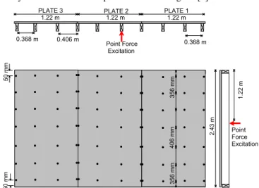
This paper, the second of two [1], examines the effect of screw location and number on the power flow from a wood stud to directly attached gypsum board. It is necessary to evaluate how an offset distance between the point of an applied force and the fastening point affects the power transmitted from the stud to the gypsum board because if the wall has resilient channels drive points and fastening points will not be aligned. Earlier studies had always considered that the points would be aligned [2].
1.22 m 1.22 m 1.22 m 0.406 m
PLATE 3 PLATE 2 PLATE 1
Point Force Excitation Point Force Point Force Excitation 2 .4 3 m 1 .2 2 m 5 0 m m 0.368 m 0.368 m 5 0 m m 4 0 6 m m 3 5 6 m m 3 5 6 m m
Figure 1: Sketch of the construction under investigation. Figure 1 shows that the wall evaluated in this paper consists of a single layer of 16 mm Type X gypsum board attached to 35 x 85 mm clear western red cedar studs, spaced 406 mm on centre. A single point force was applied to one of the studs. The number and the location of the screws securing the gypsum board to the excited stud were systematically changed and the transmitted power evaluated.
2. EVALUATION METHOD
It is not practical to measure the power transmitted by a junction directly – indirect evaluation is necessary. Statistical energy analysis (SEA) may be used if both of the connected elements satisfy the conditions of a subsystem – modes are spaced equally in the frequency band and create a uniform energy density proportional to the damping. This allows one to write,
=
ω
η
1 12 2 1 2 SEA 12E
W
m
m
10
VLD
,log
(1)where subscript 1 indicates source, 2 receiver, and m is mass, W is
transmitted power, E is energy, and ω is angular frequency. The
equation shows the measured VLD is inversely proportional to the
transmitted power, W12, and proportional to the energy contained
in the source subsystem, E1. This approach will be used in this
paper. Mobility models are used to obtain an expression for the
transmitted power, W12.
To accurately evaluate the power flow it is necessary to determine what elements of the wall form the source and receive
subsystems. The source subsystem is the excited stud. The receiving subsystem is more complicated because it may be one or all three sheets of gypsum board. To define the receiving subsystem the vibration level of the gypsum board was measured using a scanning laser vibrometer
Figure 2 shows that at 315 Hz the energy level of plate 2 is significantly greater than that of plates 1 and 3, which are not directly attached to the excited stud. The same trend is exhibited for frequencies above 250 Hz. Below this frequency the vibration levels are significantly more uniform and at about 80 Hz modal patterns are clearly evident. Thus, for 250 Hz and above the receiving subsystem is effectively that of gypsum board plate 2, while below this frequency it would be best to treat the receiving subsystem as being all three gypsum board sheets plus all studs except for the excited one.
The VLD between the excited stud and plate 2 of the gypsum board is used to gage the power flow through the screws.
PLATE 3
PLATE 2
PLATE 1
Figure 2: Surface velocity map of the gypsum board at 315 Hz when excited by the single stud shown in Figure 1. Plate 2, which is excited by the stud, is clearly identifiable by the higher levels.
3. EFFECT OF SCREW LOCATION AND NUMBER
It is has been assumed that the transmitted power is proportional to the number of screws [Error! Bookmark not
defined.]. This implies two things. First, the VLD for a single
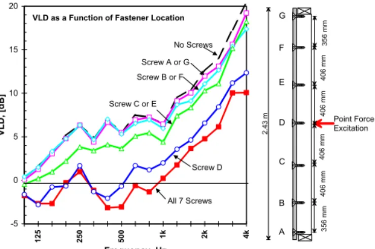
screw will be independent of screw location. Second, when there are two or more screws, the motion of each is incoherent. Figure 3 clearly shows that with the screw at location “D” (immediately opposite from the source) there is significantly lower VLD (hence significantly more transmitted power) than any other position. VLD ranking indicates less power is transmitted as the fastening point is moved away from the source.
To explain this it is necessary to examine equation 1 and vibration level of the stud in more detail. If the stud were an ideal
subsystem, the energy, E1, would be spatially uniform, but highly
localized energy and the space average result may not be meaningful when there are one or a few point connections.
Figure 4 shows the measured VLD for screw locations B, C, D and E when the energy of the stud near the screw is normalized to a common level. There is considerably better agreement between the sets of data indicating that at points B, C, D and E the ratio of
energy, E1, to transmitted power, W12, is reasonably invariant.
Figure 3: VLD as a function of the location of a single screw attaching the gypsum board to the excited stud. Also shown are the cases with all 7 screws installed and the case with no screws.
Figure 4: VLD as a function of the location of a single screw. VLD’s computed using stud velocity levels local to points of fastening rather than the space-averaged results used in Figure 3.
It is important to note that the VLD (of Figure 3) does not become very large when there are no screws even though the head and sole plates of the wall are cut on either side of the excited stud. This suggests that although there are no screws there may still be points where the stud and gypsum board touch and transmit power although less effectively than if there were a screw. This prevents evaluation of points A, F, and G. However, the mobilities at all seven of the screw locations were similar which would suggest that for these points the ratio of energy to transmitted power should be invariant, too.
Having demonstrated that if the energy of the stud is spatially uniform then the transmitted power is reasonably independent of
location the next step is to evaluate the assumption that the total power transmitted is proportional to the number of screws. This has been previously observed [2] for all frequencies for which the bending wavelength in the gypsum board (the least stiff element) is less than twice the screw spacing.
Figure 5 shows the measured change in VLD due to removing four (F, E, D and B) of the seven screws. Assuming the stud energy is uniform, the VLD should increase by 10log(7/3) or 3.7 dB. Inspection of Figure 3 and Figure 4 as well as inspection of the stud velocity levels indicates that of the three points A, D and G, only D contributes significantly. Similarly, only E, D, and C contribute significantly when all seven screws are installed. Thus, the predicted change in VLD will be approximately 10log(3/1) or 5.1 dB. Figure 5 shows there is good agreement for frequencies above about 160 Hz. Below 160 Hz one should not expect good agreement because the stud and gypsum board will be effectively line-connected because the bending wavelength in the gypsum board is more than twice the screw spacing (406 mm). VLD as a Function of Fastener Location
-5 0 5 10 15 20 125 250 500 1k 2k 4k Frequency, Hz VL D, [d B] All 7 Screws Screw D Screw C or E Screw B or F Screw A or G No Screws Point Force Excitation 2 .4 3 m 4 0 6 m m 4 0 6 m m A B C D E F G 3 5 6 m m 4 0 6 m m 4 0 6 m m 3 5 6 m m
Figure 5: Change in VLD due to reducing the effective number of screws from 3 to 1. -6 -4 -2 0 2 4 6 8 10 63 125 250 500 1k 2k 4k Frequency, Hz V L D Change, [dB] Measured Predicted simple theory Change in VLD
due to reducing the number of screws
Measured VLD
using stud velocity levels local to the screw
-5 0 5 10 15 125 250 500 1k 2k 4k Frequency, [Hz] Local ised V L D, [dB] Screw B Screw C Screw D -- Middle Screw E Point Force Excitation 2 .4 3 m 4 0 6 m m 4 0 6 m m A B C D E F G 3 5 6 m m 4 0 6 m m 4 0 6 m m 3 5 6 m m
4. DISCUSSION AND CONCLUSIONS
This paper has shown that a wall consisting of a single layer of gypsum board attached to a single row of wood studs acts as one or more subsystems depending on frequency. Above about 250 Hz, there are three subsystems. The ratio of transmitted power to source (stud) energy is reasonably independent of screw location, which is to be expected as the measured mobilities do not change appreciably if the distance from the edge was greater than 50 mm.
Because the stud is highly damped and has low modal density (i.e., poor subsystem approximation) the energy will not be uniform and the power flow will not be the same at all points. Having only one drive point (point source) represents an extreme case but illustrates the need to recognise that there will be less power transmitted by screws far from the source. Consequently, it may be necessary to include the effect of near field vibration levels in the models.
5. REFERENCES
1 T.R.T. Nightingale & Katrin Kohler, (2003), Canadian Acoustics, Vol. 31(3).
2 R.J.M. Craik, R.S. Smith, (2000) “Sound transmission through lightweight parallel plates,” Applied Acoustics, Vol. 61, pp. 247-269.