HAL Id: hal-01759258
https://hal.archives-ouvertes.fr/hal-01759258
Submitted on 5 Apr 2018
HAL is a multi-disciplinary open access
archive for the deposit and dissemination of
sci-entific research documents, whether they are
pub-lished or not. The documents may come from
teaching and research institutions in France or
abroad, or from public or private research centers.
L’archive ouverte pluridisciplinaire HAL, est
destinée au dépôt et à la diffusion de documents
scientifiques de niveau recherche, publiés ou non,
émanant des établissements d’enseignement et de
recherche français ou étrangers, des laboratoires
publics ou privés.
High speed pulsed electrical spin injection in spin-light
emitting diode
V. Truong, P.-H Binh, Pierre Renucci, M. Tran, Y. Lu, H. Jaffres, J.-M.
George, C. Deranlot, A. Lemaitre, Thierry Amand, et al.
To cite this version:
V. Truong, P.-H Binh, Pierre Renucci, M. Tran, Y. Lu, et al.. High speed pulsed electrical spin
injection in spin-light emitting diode. Applied Physics Letters, American Institute of Physics, 2009,
94 (141109), �10.1063/1.3110990�. �hal-01759258�
High speed pulsed electrical spin injection in spin-light emitting diode
V. G. Truong,1P.-H. Binh,2P. Renucci,1,a兲M. Tran,3Y. Lu,3H. Jaffrès,3J.-M. George,3C. Deranlot,3A. Lemaître,4T. Amand,1and X. Marie1
1
Université de Toulouse, INSA-CNRS-UPS, LPCNO, 135 Avenue de Rangueil, 31077 Toulouse, France
2
Institute of Material Science, 18 Hoang Quoc Viet Road, Cau Giay Dist, Hanoï 10000, Vietnam
3
Unité Mixte de Physique CNRS/Thales, RD 128, 91767 Palaiseau, France and Université Paris-Sud 11, 91405 Orsay, France
4
CNRS-Laboratoire de Photonique et Nanostructures, Route de Nozay, 91460 Marcoussis, France 共Received 22 December 2008; accepted 10 March 2009; published online 10 April 2009兲
We demonstrate high speed pulsed electrical spin injection from a CoFeB/MgO spin injector into a AlGaAs/GaAs semiconductor light emitting diode. Under pulsed electrical excitation, time-resolved electroluminescence on nanosecond time scale exhibits a plateau of circular polarization degree as high as 15% under a 0.8 T magnetic field. It follows an initial decay that could be due to electron spin-relaxation process in the quantum well embedded in the intrinsic region of the diode. The temporal buildup of the electronic spin polarization degree in the quantum well is much faster than the rise time of electroluminescence intensity. © 2009 American Institute of Physics.
关DOI:10.1063/1.3110990兴
The manipulation of the spin degree of freedom in semi-conductors could yield to devices with additional functional-ities. Various experiments have been performed in order to electrically generate1 and control spin-polarized carriers in semiconductors, in particular for high speed applications.2 Besides these schemes, a promising one could consist in in-jecting spin-polarized currents in pulsed regime from a fer-romagnetic 共FM兲 source into a semiconducting heterostruc-ture. For this purpose, an efficient injection of spin-polarized electrons can be obtained by the insertion of a thin tunnel barrier3 at the interface between both types of materials. In particular MgO tunnel barriers yield very efficient spin injection,4–6 thanks to the symmetry selection rules which govern the tunneling transfer of carriers.7 One of the most powerful tools to estimate the spin injection efficiency is based on the optical detection8–10in devices called spin-light emitting diodes共spin-LEDs兲 with a quantum well 共QW兲 em-bedded in the intrinsic region of the diode. The electron spin polarization within the semiconductor can be inferred from the measured circular polarization of the electroluminescence signal共EL兲 through optical selection rules11for a QW. To the best of our knowledge, only quasistationary 共cw兲 operating mode for electrical spin injection has been evidenced up to now by EL measurements. For future applications, it is also important to demonstrate very high speed pulsed operation. This could appear as a cornerstone for the generation of high speed spin currents as well as the fast initialization of quan-tum memories based on spin.
In this letter, we explore the ability of such device to be operated under pulsed electrical excitation by time-resolved EL, and we report on the ultrafast electrical injection of spin-polarized electrons in a CoFeB/MgO/AlGaAs structure. A quasiconstant circular polarization degree 共Pc兲 as large as
15% at T = 15 K for a magnetic field of 0.8 T under electrical pulsed excitation is evidenced during the very short nanosec-ond window of light emission. This plateau behavior for Pc
occurs after an initial decay that could be due to electron
spin-relaxation process. In addition, it is established that the electron spin polarization reaches its maximum value before the first 700 ps of the EL emission.
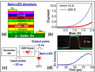
The spin-polarized light emitting diode structure 关see Fig. 1共a兲兴 was grown by molecular beam epitaxy 共MBE兲 for the semiconductor part before depositing the tun-nel barrier/ferromagnet contact by sputtering method. The p-i-n LED device has the following structure sequence:
p-GaAs:Zn 共001兲 substrate 共p=2⫻1019 cm−3兲/500 nm p-Al0.08Ga0.92As: Be 共p=1.7⫻1019 cm−3兲/50 nm undoped
Al0.08Ga0.92As/10 nm undoped GaAs /50 nm undoped
Al0.08Ga0.92As/50 nm n-Al0.08Ga0.92As: Si 共n=1
⫻1016 cm−3兲. The LED was passivated with arsenic in the
MBE chamber and then transferred in air into a magnetron sputtering system to grow the CoFeB/MgO spin injector. Be-fore that, the As capping layer was first desorbed at 400 ° C by in situ reflection high energy electron diffraction control in a separate chamber connected to the main sputtering chamber. The spin injector consists of a MgO tunnel barrier
a兲Electronic mail: [email protected].
FIG. 1.共Color online兲 共a兲 Spin-LED structure. 共b兲 I共V兲 characteristics at 15 K共thick line兲 and 300 K 共thin line兲. 共c兲 Scheme of the high speed electrical pulse generator.共d兲 Up: time evolution of electrical pulse measured by a fast sampling oscilloscope in the 2 ns range. Down: rising edge of the EL of a VCSEL measured by the streakscope with a temporal resolution of 25 ps.
APPLIED PHYSICS LETTERS 94, 141109共2009兲
0003-6951/2009/94共14兲/141109/3/$25.00 94, 141109-1 © 2009 American Institute of Physics Downloaded 04 May 2009 to 194.214.217.17. Redistribution subject to AIP license or copyright; see http://apl.aip.org/apl/copyright.jsp
with a thicknesses of 2.6 nm grown at 200 ° C, followed by a 3 nm Co40Fe40B20FM contact capped with 5 nm Ta layer
to prevent oxidation. The sputtering conditions for MgO and metals can be found elsewhere.12 Circular mesas with 300 m diameter were then processed using standard pho-tolithography and etching techniques.
The EL measurements are performed at low temperature 共15 K兲 in a helium closed-cycle cryostat. For quasi-cw EL, the sample is excited with square pulses of 5 s at 50 kHz. For time-resolved EL, an electrical impulse generating cir-cuit using a step recovery diode 共SRD兲 共Ref. 13兲 from
MMD-0840 Aeroflex-Metelics Corporation, is inserted in the cryostat and driven by a square-pulsed generator with a pulse duration of 25 ns and rise and fall times of 3 ns关Fig.1共c兲兴. The repetition rate is 2 MHz. We have characterized the im-pulse forming circuit with a fast sampling oscilloscope 共Tek-tronic 3S1 sampling head兲 with a temporal resolution of 350 ps 关Fig. 1共d兲兴: the square pulse duration is 4 ns. For the polarization resolved EL measurements, the spin-LED is placed into a Helmoltz-split magnetic coil providing a maxi-mum magnetic field共B兲 of 0.8 T normal to the sample plane. The EL signal is detected in the Faraday geometry. The EL circular polarization degree Pc is analyzed through a /4
wave plate and a linear analyzer and is defined as PC=共I+
− I−兲/共I++ I−兲 where I+and I−are the intensities of the right 共+兲 and left 共−兲 circularly polarized components of
the luminescence, respectively. Two different ways of detec-tion are available:共i兲 a very low noise charged-coupled de-vice with a monochromator is used for cw measurements 共the spectral resolution of the whole setup is of about 2 meV兲; 共ii兲 a streakscope with a S20 photocathode is synchro-nized with the pulsed generator to measure the time resolved EL with a temporal resolution of 125 ps共for the range used for the measurements in this paper兲 in photon counting mode. Using the latter detector, we have characterized the electrical pulse provided by the impulse forming circuit through the EL of an ultrafast vertical cavity surface emitting laser 共VCSEL兲 850 nm 共HFE4080–321-XBA, Honeywell兲. The rise 关see Fig. 1共d兲兴 and fall times are estimated about 100⫾25 ps 共the streakscope is used with its fastest time range, corresponding to a temporal resolution of 25 ps兲, that is consistent with the transition time of 75 ps of the SRD embedded in the impulse forming circuit.
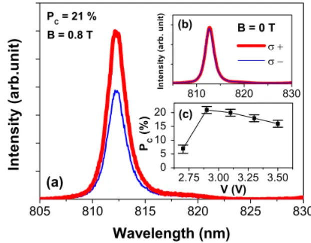
Figure2 shows typical cw EL spectra acquired at 15 K under V = 2.9V bias for B = 0 关inset 共b兲 in Fig. 2兴 and 0.8 T
关Fig. 2共a兲兴. Whereas the heavy-hole exciton 共XH兲 EL peak observed at 812 nm does not show any circular polarization at zero magnetic field, the EL polarization reaches 21%⫾2% under 0.8 T.14According to the optical selection rules applied to QW,11 the EL circular polarization PC is proportional to
the electron spin polarization PE 共PC= FPE兲. The factor F
= 1/共1+/s兲 takes into account the electron spin relaxation
sduring its lifetimein the QW.
6,15–17
F is estimated to be
around 0.50⫾0.03 by independent measurements of s
共⬇450⫾35 ps at 1/e兲 and共⬇450⫾20 ps at 1/e兲 by time-resolved photoluminescence6共TRPL兲. The time evolution of the photoluminescence degree of circular polarization Pc
共af-ter a 1.5 ps共+兲 laser pulsed excitation at 1.653 eV兲 is
dis-played in the inset in Fig.3共b兲. From this measurement, it is possible to extract s⬇450⫾35 ps. So the electrons spin
polarization PE in the semiconductor part, before electrons
are trapped in the QW can be estimated to be about PE
= 42%⫾6%. Let us note that the saturation field for CoFeB measured by superconducting quantum interference device 共SQUID兲 magnetometer measurements is 1.3 T. An extrapo-lation procedure by matching the EL polarization results with the SQUID data in the linear regime6allows a rough estimate of PE at saturation; we find PE⬃68%⫾10%, proving the
very high efficiency of CoFeB/MgO spin injector. The bias dependence of PCis shown in the inset共c兲 of Fig.2. After a
first increase toward a maximum regime of 21%, PC
monoto-nously decreases with the applied voltage. This trend has also been observed by Adelmann et al.17,18and Dong et al.19 for different FM spin injectors. These authors attribute this dependence to the variation in the ratio/sas a function of
the applied voltage.
FIG. 2. 共Color online兲 共a兲 EL spectra at 15 K under an external magnetic field of 0.8 T for I+共thick line兲 and I−共thin line兲 EL components. Inset 共b兲 same quantities for B = 0 T. Inset共c兲 bias dependence of the EL polarization degree PC共B=0.8 T兲.
FIG. 3. 共Color online兲 共a兲 Right axis: time-resolved EL intensity at T = 15 K of the+共thick line兲 and−共thin line兲 polarized components with an applied bias V = 4 V for B = 0.8 T. Left axis: time evolution of the EL circular polarization degree PC共open circles兲. The dotted line is a guide for the eyes.共b兲 Right axis: time-resolved EL intensity at T=15 K of the+ 共thick line兲 and −共thin line兲 polarized components with an applied bias
V = 4 V for B = 0 T. Left axis: time evolution of the EL circular polarization PC 共open circles兲. Inset: time evolution of the circular polarization degree
PCof the PL at T = 15 K after a 1.5 ps共+兲 laser pulsed excitation at 1.653 eV共above AlGaAs gap兲.
141109-2 Truong et al. Appl. Phys. Lett. 94, 141109共2009兲
After the characterization of spin injection by cw and spectrally resolved EL, we turn now to the study of time-resolved EL in the nanosecond range performed on the XH peak. Figure 3 共right axis兲 shows time-resolved EL spectra
for I+and I−intensities acquired at 15 K for B = 0.8 T共the applied bias is V = 4 V兲. The time origin t=0 is chosen when the EL signal appears, that is 1700 ps after the rising edge of the electrical pulse. We observe first an increase of the EL signal with a rise time of about 1250⫾125 ps 共measured between 10% and 90% of maximum signal兲, followed by a sudden drop with a characteristic time at 共1/e兲 of 200⫾125 ps, close to the temporal resolution of our setup. This slow EL rise time, compared to the fast rise time共100 ps兲 of the applied voltage, is due to parasitic resistances, inductances, and capacitances of the device. The temporal window for EL emission共around 2.4 ns at the foot of the EL pulse兲 is shorter than the electrical pulse duration 共about 4 ns兲: it could be due to the fact that the threshold voltage for EL emission is only reached for this window. The very fast quenching of the EL signal in 200 ps indicates that the life-time of carriers during the fall of the electrical pulse is no more governed by radiative recombinations. This is opposite to the case of TRPL measurements under pulsed laser exci-tation where a characteristic lifetime at 共1/e兲 of 450⫾35 ps was previously measured6at 15 K. The fast de-crease of EL intensity could be ascribed to the sweep of carriers out of the QW corresponding to a short reverse peak current at the end of the electrical pulse. The analysis of this dynamical behavior is currently under investigation and is beyond the scope of this paper. The time evolution of the EL circular polarization degree Pccan be deduced from I+and
I− intensities and is displayed on the left axis of Fig. 3. When a longitudinal magnetic field of 0.8 T is applied, an EL circular polarization is evidenced关Fig.3共a兲兴, whereas no cir-cular polarization can be detected for B = 0 关Fig.3共b兲兴. This
demonstrates a rapid establishment of the current-spin polar-ization below the nanosecond scale. Due to a poor signal to noise ratio, it is however not possible to determine PC共t兲
during the first 700 ps of the dynamics. From 700 ps to 1000 ps, Pc decreases and then remains quasiconstant
共⬇15%⫾3%兲 during the whole dynamics. This could be due to electron spin relaxation in the QW measured previously, and could be responsible for the circular polarization de-crease during the rising time of EL, before the system reaches a quasistationary regime after around 1 ns共from the point of view of Pc evolution兲. The presence of a large
cir-cular polarization as soon as any EL signal is detectable proves unambiguously that the build-up time of the elec-tronic spin polarization in the QW embedded in the intrinsic region of the diode is much faster than the rise time of EL signal. The former takes place on a time scale at least shorter than 700 ps.
In conclusion, we have demonstrated high speed pulsed electrical spin injection from CoFeB/MgO spin injector into a AlGaAs/GaAs semiconductor light emitting diode. This in-jection is characterized by an EL circular polarization plateau
as high as 15% during the short nanosecond windows of light emission at 15 K under a 0.8 T magnetic field. This plateau occurs after an initial decay that may be due to elec-tron sprelaxation process in the QW embedded in the in-trinsic region of the diode. We observe that the rise time of electronic spin polarization rate in the QW is much faster than the rise time of EL. Note that the time response of the device could be shortened by reducing the size of the mesa and by using an undoped substrate with air bridges to reduce its capacitance. This could allow the excitation of the device with electrical pulses shorter than 250 ps in order to follow more accurately the spin dynamics as well as to get the elec-trical spin injection at a higher repetition rate.
We thank A. Balocchi and B. Urbaszek for fruitful dis-cussions. This work is partially supported by the French Agence Nationale pour la Recherche 共ANR兲, contract MO-MES.
1V. Sih, W. H. Lau, R. C. Myers, V. R. Horowitz, A. C. Gossard, and D. D. Awschalom,Phys. Rev. Lett. 97, 096605共2006兲.
2N. P. Stern, D. W. Steuerman, S. Mack, A. C. Gossard, and D. D. Awschalom,Nat. Phys.4, 843共2008兲.
3A. Fert and H. Jaffrès,Phys. Rev. B 64, 184420共2001兲.
4X. Jiang, R. M. Shelby, R. M. Macfarlane, S. R. Bank, J. S. Harris, and S. S. P. Parkin,Phys. Rev. Lett. 94, 056601共2005兲.
5T. Manago, A. Sinsarp, and H. Akinaga, J. Appl. Phys. 102, 083914 共2007兲.
6Y. Lu, V. G. Truong, P. Renucci, M. Tran, H. Jaffrès, C. Deranlot, J.-M. George, A. Lemaître, Y. Zheng, D. Demaille, P.-H. Binh, T. Amand, and X. Marie, Appl. Phys. Lett. 63, 054416共2008兲.
7W. H. Butler, X.-G. Zhang, T. C. Schulthess, and J. M. MacLaren,Phys. Rev. B 63, 054416共2001兲.
8A. G. Aronov and G. E. Pikus, Sov. Phys. Semicond. 10, 698共1976兲. 9R. Fiederling, M. Keim, G. Reuscher, W. Ossau, G. Schmidt, A. Waag,
and L. W. Molenkamp,Nature共London兲 402, 787共1999兲.
10Y. Ohno, D. K. Young, B. Beschoten, F. Matsukura, H. Ohno, and D. D. Awschalom,Nature共London兲 402, 790共1999兲.
11F. Meier and B. P. Zakharchenya, Optical Orientation 共North-Holland, Amsterdam, 1984兲.
12Y. Lu, C. Deranlot, A. Vaurès, F. Petroff, J.-M. George, Y. Zheng, and D. Demaille,Appl. Phys. Lett. 91, 222504共2007兲.
13J. S. Lee and C. Nguyen,Electron. Lett. 37, 504共2001兲.
14The parasitic effects due to Magnetic Circular Dischroism and to the elec-tron Zeeman splitting in the QW have been measured by photolumines-cence spectroscopy under linearly polarized excitation light. We found that these effects yield a circular polarization degree PC⬍2% for B=0.8 T. This point was also confirmed by a control measurement on a device with a Pt layer instead of CoFeBo.
15B. L. Liu, P. Renucci, H. Carrère, M. Sénès, X. Marie, T. Amand, J. F. Bobo, C. Fontaine, A. Arnoult, and P. H. Binh,Phys. Status Solidi C 1,
475共2004兲.
16G. Salis, R. Wang, X. Jiang, R. M. Shelby, S. S. P. Parkin, S. R. Bank, and J. S. Harris,Appl. Phys. Lett. 87, 262503共2005兲.
17C. Adelmann, X. Lou, J. Strand, C. J. Palmstrom, and P.A. Crowell,Phys. Rev. B 71, 121301共R兲 共2005兲.
18C. Adelmann, J. L. Hilton, B. D. Schultz, S. McKernan, C. J. Palmstrom, X. Lou, H. S. Chiang, and P. A. Crowell,Appl. Phys. Lett. 89, 112511
共2006兲.
19X. Y. Dong, C. Adelmann, J. Q. Xie, C. J. Palmstrom, X. Lou, J. Strand, P. A. Crowell, J. P. Barnes, and A. K. Petford-Long,Appl. Phys. Lett. 86,
102107共2005兲.
141109-3 Truong et al. Appl. Phys. Lett. 94, 141109共2009兲