Design and Evaluation of a Device for Measuring 3D-Micromotions of
Press-Fit Femoral Stern Prostheses
Bühler D.W., Brunner R, Nolte L.-P.
M.E. Müller Institute for Biomechanics, University of Bern, 3010 Bern, Switzerland
INTRODUCT1ON
Primary stability of uncemented total hip replacements is regarded äs a major factor necessary for good quality bony ongrowth to the prosthetic femoral stem and therefore for a successrul long-term outcome [1,2]. The remodelling of the endothelial bone in contact with the implant is affected by the relative micromotions of the bone-implant interface and the stress state in the femoral bone. As a result, for optimal biological fixation, translational movements (i.e. primary stability) are of greatest interest. These interface-micromotions generally occur in all three spatial directions. Under physiologic loading, they consist of a cyclic amplitude and change in the mean, which in the cranio-caudal direction represents subsidence of the prosthesis.
Existing measurement strategies which are based on dial gauges, extensometers, LVDTs, hall effect transducers or strain gauge techniques provide information about only one component of the general three-dimensional micromovement [3,4,5]. Furthermore, fixation of sensors away from the point of interface motion measurement, äs seen in various studies [4,5], may result in the registration of motions due to elastic deformation of the femoral or prosthetic shaft in addition to the interface motion.
The objective of this study was to develop, validate, and apply a new technique which allows the precise
measurement of the isolated 3D interface motion at three
different points along the femoral shaft.
Local Sensor COS
Thermistor,
Global Prosthetic
x· cos
Rod Linear Spring Custom Ball and Socket Joint
Adapter Unrt Zero Adjustment Screws
Measuring Points
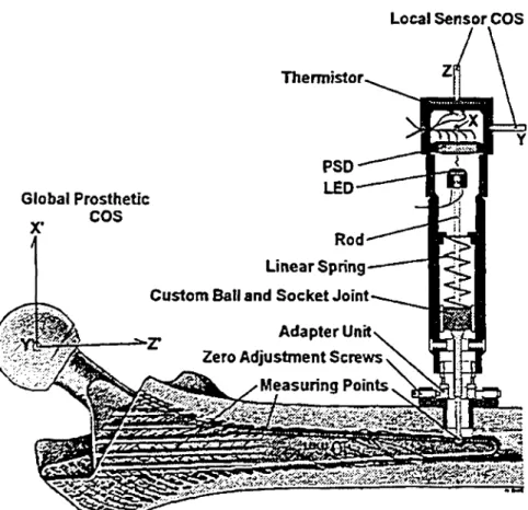
Figure 1: Conceptual Design ofthe Sensor
MATERIALS AND METHODS
The present measuring technique is based on a sensor combining optoelectronic with precision mechanical components. Spherical measuring tips of three sensors were placed on the prosthesis at predefined locations: the distal tip of the prosthesis and at the middle and proximal third of the femoral stem. The sensors were mounted on an adapter unit which was anchored in a transverse 9 mm hole drilled in the cortex. Precision, play-free, ball bearing mechanisms allowed transition of the detected motion to a infrared emitting diode on the opposite end of the sensor (Fig. 1). Photons emitted by this LED were registered by a two dimensional silicon position sensitive detector (PSD). The AT-movements of the LED were measured directiy by the PSD. Micromovement of the prosthesis in the Z-axis of the transducer brings the LED closer or farther to the photodiode, thereby increasing or decreasing the intensity of the light beam on the PSD. Since the two-dimensional position sensitive detector generates photocurrents, which sum is proportional to the intensity, the highly non-linear correlation between LED-PSD distance and light intensity was used to acquire the third dimension at the same time äs measuring the XY-motions. Due to the triermal response of the PSD, a ntc-resistor was also integrated to exclude thermodrifts during long-tenm testing.
Static and dynamic validation indicated that the maximum System error was ±4.9 microns within a measuring ränge of ±0.75 mm in each spatial orientation.
To demonstrate the Utility of the sensors in interface motion measurement, an in-vitro experiment was performed. Seven paired fresh cadaveric femora were used for testing two different types of uncemented femoral stems: CLS stem (Spotorno) and Cone prosthesis (Wagner) both from Protek AG, Switzerland. Using a custom loading rig the femora were subjected to sinusoidal cyclic loading in a bi-axial materials testing machine. A cranio-caudal force FCC with a frequency of l Hz was combined with a 0.5 Hz antero-posterior force Fap having a magnitude of 10% of FCC. Loading Steps of l-, 2- and 3-times body weight (BW) were applied. Custom Software allowed for real-time graphical display of the applied forces and the detected movements.
RESULTS
The postprocessing Software allowed the analysis of: (A)
Three-dimensional motion displayed in cylindrical
coordinates (Fig. 2); (B) Motion amplitude (MA), which is the difference of the measured minimum and maximum
value for one loading cycle and (C) Total motion (TM),
which is the time-based average micromotion of one
loading cycle (Fig. 3).
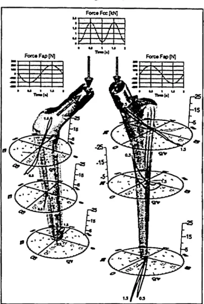
(A) Three-Dimensional Motion: A typical 3D
interface motion behavior for one loading cycle (loading
step 3: Fcc=2.07 kN; Fap=207 N) is illustrated for both
types of prostheses in Fig. 2. The midshaft of both
prostheses was the point with the least motion in all
directions. At the distal tip the Cone prosthesis also
showed very little movement. A comparably large MA
was measured at the proximal position for both
prostheses. This motion loop was mainly oriented in the
X'Z' -plane (=frontal, see figure 1).
for all seven paired tested femora is presented in Fig. 3
(for axes orientation refer to Fig. 1).
Fo«e«Fecp<NJ
Figure 2: SD-Motion Analysis
(B) Motion Amplitude: At higher forces the MA
measured in a loading cycle increased for both prostheses.
All MA values for the CLS prosthesis measured at the
middle third and proximal third of the femoral stem were
larger in every direction than the values for the Cone
prosthesis (values for 3xBW: CLS frorn 20 to 87μηι,
Cone from 12 to 35μιη). However, at the proximal end of
the shaft the Cone prostheses allowed a larger MA (CLS
from 26 to 78um, Cone from 50 to 120 um). In most
cases the largest single component of the MA was found
in the mediolateral direction.
(C) Total Motion: At the end of the first and
second loading step both prostheses showed relatively
small TM in any of the motion directions at the various
measurement points. In the third loading step TM for both
prostheses became much larger with the main increase
during the first 250 cycles. At the end of stage 3 the TM
of the Cone was larger than the TM of the CLS prosthesis
at all measuring positions. The caudal subsidence was the
largest contributor to the TM for both prostheses. In X*
(M-L) and Y' (A-P) directions the Sterns appeared more
stable. The average TM at the distal tip of the prosthesis
1000