HAL Id: insu-01182800
https://hal-insu.archives-ouvertes.fr/insu-01182800
Submitted on 25 Nov 2020
HAL is a multi-disciplinary open access
archive for the deposit and dissemination of
sci-entific research documents, whether they are
pub-lished or not. The documents may come from
teaching and research institutions in France or
abroad, or from public or private research centers.
L’archive ouverte pluridisciplinaire HAL, est
destinée au dépôt et à la diffusion de documents
scientifiques de niveau recherche, publiés ou non,
émanant des établissements d’enseignement et de
recherche français ou étrangers, des laboratoires
publics ou privés.
First flight in space of a wide-field-of-view soft x-ray
imager using lobster-eye optics: Instrument description
and initial flight results
Michael R. Collier, Frederik S. Porter, David G. Sibeck, Jenny A. Carter,
Meng P. Chiao, Dennis J. Chornay, Thomas E. Cravens, Massimiliano
Galeazzi, John W. Keller, Dimitra Koutroumpa, et al.
To cite this version:
Michael R. Collier, Frederik S. Porter, David G. Sibeck, Jenny A. Carter, Meng P. Chiao, et al.. First
flight in space of a wide-field-of-view soft x-ray imager using lobster-eye optics: Instrument description
and initial flight results. Review of Scientific Instruments, American Institute of Physics, 2015, 86 (7),
pp.071301. �10.1063/1.4927259�. �insu-01182800�
Lobster-Eye Optics: Instrument Description and Initial Flight Results
Michael R. Collier,1, a)F. Scott Porter,1, b) David G. Sibeck,1, c) Jenny A. Carter,2, d) Meng P. Chiao,1, e)Dennis
J. Chornay,1, f) Thomas E. Cravens,3, g) Massimiliano Galeazzi,4, h) John W. Keller,1, i) Dimitra Koutroumpa,5, j)
Joseph Kujawski,6, k) Kip Kuntz,7, l) Andy M. Read,2, m) Ina P. Robertson,3, n) Steve Sembay,2, o) Steven
Snowden,1, p) Nicholas Thomas,1, q) Youaraj Uprety,4, r) and Brian M. Walsh8, s) 1)NASA/Goddard Spaceflight Center, Greenbelt, MD
2)
The University of Leicester, The Department of Physics and Astronomy, Leicester, LE1 7RH, U.K.
3)
University of Kansas, Department of Physics and Astronomy, 1251 Wescoe Hall Dr., Lawrence, Kansas, 66045
4)University of Miami, Department of Physics, Coral Gables, Florida 33124 5)
CNRS/INSU, LATMOS-IPSL; Universit´e Versailles St-Quentin; Sorbonne Universit´es, UPMC Univ. Paris 06, 11 Boulevard d’Alembert, 78280 Guyancourt, France
6)Department of Physics, Siena College, Loudonville, New York
7)The Johns Hopkins University, The Henry A. Rowland Department of Physics and Astronomy, Baltimore,
Maryland 21218
8)
Space Sciences Laboratory, University of California, Berkeley, CA (Dated: 27 June 2015)
We describe the development, launch into space, and initial results from a prototype wide field-of-view (FOV) soft X-ray imager that employs Lobster-eye optics and targets heliophysics, planetary, and astrophysics science. The Sheath Transport Observer for the Redistribution of Mass (STORM) is the first instrument using this type of optics launched into space and provides proof-of-concept for future flight instruments capable of imaging structures such as the terrestrial cusp, the entire dayside magnetosheath from outside the magnetosphere, comets, the moon, and the solar wind interaction with planetary bodies like Venus and Mars.1
PACS numbers: xxxxx
I. INTRODUCTION
The solar wind plasma flows continuously from all lati-tudes and longilati-tudes on the sun occupying the entire he-liosphere and interacting with the neutral gas inside it. Although the solar wind is mostly protons, it also con-tains a flux (>105/cm2/s) of high charge state heavy ions
such as O+7. When these high charge state heavy ions
a)[email protected] b)[email protected] c)[email protected] d)[email protected] e)[email protected] f)[email protected] g)[email protected] h)[email protected] i)[email protected] j)[email protected] k)[email protected] l)[email protected] m)[email protected] n)[email protected] o)[email protected] p)[email protected] q)[email protected] r)[email protected] s)[email protected]
interact with neutral gas, many undergo charge exchange reactions, acquiring an electron. Almost immediately af-terwards, the high charge state ions emit soft (below a couple of keV) X-ray photons.2
This process is known as soft X-ray emission due to solar wind charge exchange recombination, or SWCX, and it occurs throughout the solar system and beyond: in planetary atmospheres, comets, interplanetary space, Earth’s exosphere, and likely in supernova remnants and other regions where astrophysical plasmas interact with the neutral interstellar medium. The study of SWCX is truly cross-disciplinary.
Relevance to Heliophysics: The terrestrial magnetic field carves a cavity in the solar wind known as the mag-netosphere. All of the mass, momentum, and energy powering geomagnetic storms is supplied by the solar wind. Because geomagnetic storms are responsible for some of the most severe space weather disturbances, ac-curate forecasts from global numerical simulations that incorporate the fundamental physics are essential.
This kind of a predictive capability requires a global view generated on a short cadence of the overall inter-action at the magnetopause, the outer boundary of the magnetosphere. Although we have had many years of in-situ spacecraft observations,3from which we have learned a great deal, these measurements are sporadic and single-point. The necessary input for large-scale models re-quires simultaneous global observations of the
magne-2
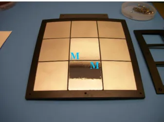
FIG. 1. The 3x3 optics holder accommodates up to nine 4 cm x 4 cm micropore reflectors with about a 9.2◦ FOV, side-to-side. DXL/STORM was flown with two micropore reflector slots populated, as shown in the figure (labeled “M”), with the others covered by aluminum blanks.
topause and magnetosheath.4 Significant SWCX emis-sion originates from the magnetosheath and deep within the magnetospheric cusps because in these locations the solar wind encounters Earth’s neutral exosphere. Fur-thermore, these regions map out and provide bound-ary conditions for the Earth’s magnetosphere. Both observations5,6 and simulations7 indicate that SWCX soft X-ray imaging will produce global images of the solar wind-magnetosphere interaction.
Relevance to Planetary Science: As comets approach the sun, they sublimate large clouds of neutral gas. The solar wind interacts with these clouds in a complex pro-cess that has been imaged and studied using soft X-ray emission.2,8–10
The solar wind-planetary body interaction can also be imaged for non-magnetized planets. Both Mars and Venus show global SWCX soft X-ray emissions from their exospheres that are similar in nature to the emission from Earth, demonstrating both the feasibility of global mag-netosheath imaging at Earth and that SWCX soft X-ray imaging will be a valuable part of future planetary mis-sions. Chandra observations in 2001 revealed a SWCX X-ray halo around Mars,11–15 while Chandra observa-tions in 2006/2007 detected SWCX soft X-rays from the Cytherian (i.e., Venusian) exosphere.16,17
Soft X-rays have also been detected from the inter-action between the solar wind and the tenuous lunar exosphere.18
Relevance to Astrophysics: All soft X-ray observations from X-ray observatories must contend with a significant spatially, temporally, and spectrally changing foreground from SWCX emission originating in the solar system.19,20
The correct interpretation of observations, particularly those of extended objects and the diffuse X-ray back-ground, requires understanding and accurate modeling of this foreground emission. For example, significant
amounts of observing time on Chandra, XMM-Newton, Suzaku, and ROSAT have been adversely affected by this emission, and scientific interpretation errors have oc-curred because of our lack of understanding of SWCX.21
Only when we understand this phenomenon fully will we be able to maximize the return on investment for these NASA, ESA, and JAXA missions.
In this paper, we report on the design, development, and launch into space of a wide FOV laboratory pro-totype instrument designed to image soft X-ray emis-sion associated with the solar wind’s interaction with terrestrial and planetary neutral atoms. Although ob-servations with astrophysics telescopes of SWCX emis-sion near Earth and around Mars and Venus demon-strate the feasibility of global imaging, a wide FOV im-ager is needed to study the important large-scale solar wind interactions (current astrophysics telescopes have FOVs<
∼0.5◦).
II. PROTOTYPE INSTRUMENT
A. Lobster-Eye Optics
There exists a wide variety of instrumental approaches to imaging soft X-rays. The conventional nested mir-ror optics used by many X-ray telescopes are designed to image point or relatively compact sources within a small field-of-view. This approach will not work for ob-jects such as the magnetosheath and cusps, the scien-tific targets of some planned missions, because of their proximity and scale. Instead, a different approach using an alternative wide optic technology like the micropore (Lobser-eye) optical element developed by the University of Leicester22,23 must be employed in an X-ray camera
designed to image these targets globally.
STORM (Sheath Transport Observer for the Redistri-bution of Mass) was flown as a piggyback experiment on the Diffuse X-ray emission from the Local galaxy (DXL) sounding rocket mission.24 DXL/STORM uses slumped
microchannel plates (MCPs) with square channels, called micropore reflectors (MPRs), that deliver wide field-of-view with low mass. Each spatial dimension of the square pores on these MPRs is nominally 20 µm. These pores form an array of channels approximating, in a small area to increase the reflecting surface and thus the effective area of the optic, a Kirkpatrick/Baez system.25
Slumping the MPR so that the channel axes are per-pendicular to the surface of a sphere causes reflected X-rays from infinity to focus on an image surface at half the sphere’s radius.26 (See Figure 1 of Collier et al.27 for a
diagram illustrating the principle of operation of a wide angle soft X-ray camera.) Focusing occurs when an X-ray photon reflects from two orthogonal walls of the channel. MPRs will fly as the focusing element of the Univer-sity of Leicester’s Mercury Imaging X-ray Spectrometer (MIXS) on the BepiColombo mission to Mercury.28,29
B. Optics Assembly
The DXL/STORM camera employs an optics holder that accommodates up to nine 4 cm x 4 cm slumped mi-cropore reflectors manufactured by Photonis Corporation (see Figure 1). The entire assembly with all facets pop-ulated has about a 9.2◦ field-of-view, side-to-side. How-ever, because of cost constraints only the central facet and one adjacent facet were populated. The remaining facets contained aluminum blanks. Furthermore, the re-sponse of the populated non-central facet was partially cut off by the edge of the detector plane position sensing anode board.
The reflectors have a 75 cm radius of curvature and a 37.5 cm focal length. The micropore reflectors were flown uncoated. In future instruments, coating will increase the MPR reflectivity.
The MPRs generate a cross-shaped point spread func-tion (PSF) with the legs resulting from photon reflecfunc-tions off one pore wall and the central focus resulting from pho-ton reflections off two adjacent pore walls. (See Figure 7 of Branduardi-Raymont et al.30) Qualitatively, the
effec-tive area versus energy plot resembles that of Figure 9 of Branduardi-Raymont et al.30with a peak near 1 keV,
falling off significantly by about 0.1 keV at the lower en-ergies and by about 2 keV at the higher enen-ergies.
The angular resolution of DXL/STORM was limited by the spatial resolution of the position-sensing to about 0.3◦ although the angular resolution of the MPRs is sig-nificantly better by about an order of magnitude.30
The micropore optics holder, shown in Figure 1, is ma-chined to the shape of a portion of a 75 cm radius sphere. The holder was populated with two of the 75 cm radius of curvature micropore reflectors bonded with filters: one in the center and one on the edge with the remaining seven pockets populated with aluminum blanks machined to the same shape as the micropore reflectors. The micro-pore reflectors and blanks were attached to the optics holder using a mixture of uralane 5750 and 6% cabosil by weight. A thin mask sits over the micropore reflector and blanks. The aluminum optics holder and mask are black anodized for stray light suppression.
Luxel Corporation filters constructed of a 2179 Angstrom polyimide layer for UV suppression and a 307 Angstrom aluminum layer for visible suppression were mounted on top of the two micropore reflectors. The MPRs served as a convenient “mesh” for supporting the filter. This approach proved superior to the standard practice of mounting the filters on a nickel mesh above the detector plane by eliminating the transmission lost to the mesh.
To test the bond between the UV filter and the micro-pore reflector, we performed ten thermal cycles on the filter-bonded MPR in a vacuum oven. The MPR spent 325 hours 48 minutes above a temperature of 37.8◦C and
the maximum measured temperature on the MPR (using a thermocouple) was 185.8◦C. The MPR was held at this maximum temperature for 21 hours 6 minutes. Over the
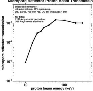
FIG. 2. The instrument response efficiency for protons im-pinging directly on the micropore reflector as function of beam energy.
entire testing, no visible change in the UV filter or MPR was observed nor in subsequent testing was there any evidence of a physical change.
In addition, in July 2012, we shake-tested the inte-grated DXL/STORM instrument at Wallops Flight Fa-cility with the UV filter attached to the micropore reflec-tor in part to test how robust the filter mounting was. In this test, we used the Black Brant IX vibration spec-ifications including a sine sweep in the thrust axis and random in all three axes at 12.7 g rms. The micropore reflector, attached UV filter, MCP detector plane plates, and all electronics survived flight level vibration.
C. Sensitivity to Energetic Particles
Protons and electrons moving in the direction of the camera optics that manage to penetrate the UV filter, avoid being scattered into the micropore walls, and end up on a trajectory towards the detector plane MCP can produce counts that are indistinguishable from X-rays. Unless the beam consists of extremely high energy unidi-rectional particles, these counts will appear as a uniform background on the detector plane.
We tested the micropore reflector and UV filter ener-getic proton suppression at the GSFC radiation facility, and the results are shown in Figure 2. The geometry of the MPR itself suppresses the flux by a factor of 103 as evidenced by the flattening of the curve with energy at high energies. At the lowest energy tested, 10 keV, the filter provides an additional factor of 102 suppression.
X-ray astronomers are very familiar with electron contamination and have been protecting against it for
4
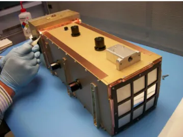
FIG. 3. The detector plane is a wedge and strip anode behind a chevron stack of MCPs coated with KBr for improved soft X-ray response. The anode board is mounted on top of the electronics box.
nearly five decades. Magnetic brooms are the stan-dard mechanism.31 Furthermore, DXL/STORM’s filters are able to stop electrons with energies less than about 3.4 keV. DXL/STORM launched from White Sands Mis-sile Range where electron contamination is insignificant even without sweeper magnets. If the launch were to oc-cur at a site where electron contamination is significant, calculations show that magnetic fields of only a couple hundred gauss (which are easily achieved) would be suf-ficient to eliminate electron contamination.
D. Detector and Electronics
The DXL/STORM detector plane is shown in Figure 3. It mounts directly to the top of the electronics box. The assembly employs a chevron configuration microchannel plate stack coated with KBr for enhanced soft X-ray sen-sitivity over a wedge-and-strip geometry anode board for position sensing.
The wedge and strip anode approach32employs an
an-ode board with interlaced pairs of wedges and strips. The wedge points are oppositely directed in each pair and the strip widths gradually change from small to large for one set and from large to small for the other set. The lo-cation that an X-ray photon hits the detector plane is determined by using the ratio of the amplitudes of the two signals from the wedges, defining the position along one axis, and the ratio of the amplitudes of the two signals from the strips, defining the position along the other axis. The resolution of the DXL/STORM anode board is about two millimeters. Although this resolution has been improved on subsequent prototypes since the DXL/STORM launch, it was more than sufficient for the DXL/STORM application, providing about 0.3◦ angular resolution.
The electronics for the DXL/STORM soft X-ray cam-era include an anode board, preamplifier and peak-hold board, Low Voltage Power Supply (LVPS) board, High Voltage Power Supply (HVPS) board, and Command and Data Handling (C&DH) board.
The DXL/STORM instrument is powered by an unreg-ulated 28V nominal line supplied on a nine pin MDM con-nector which goes directly to a DC-DC converter board. This board which employs two Virginia Power Technol-ogy converters and a filter produces the required voltages, 12V, 5V, 3.3V, and 2.2V, to power the HVPS and peak-hold boards as well as the C&DH board and its FPGA.
The high voltage is supplied to the microchannel plate stack by an HVPS board employing an EMCO Corpora-tion C50 supply controlled by a 0-5 Volt analog voltage with a voltage divider resistor chain to generate the spe-cific voltages required for each stage in the MCP stack.
The four raw signals that determine the photon posi-tion are processed by a peak-hold/preamp board generat-ing a square pulse output proportional to the amplitude of the raw signals. These pulses are then fed into ADCs on the C&DH board and read by its FPGA.
The C&DH board reads the data from the anode board, formats it, attaches a time tag, and stores the data on EEPROMs located on the board itself. In ad-dition, the C&DH board was designed, upon sensing an external pin transitioning from zero to 5V, to begin au-tonomously ramping up the high voltage on the MCP stack according to a user-defined time table and start acquiring data. This approach was implemented to min-imize requirements on rocket systems. After the instru-ment was recovered following launch, the flight data were downloaded from the EEPROMs.
All the electronics boards are integrated into a single electronics box shown in Figure 3. This box has three connectors: one 9-pin MDM connector for power, one 15-pin MDM connector for the signals, and a third 9-pin MDM connector functioning as a high voltage disable plug that shorts out the 12 Volts supplying power to the HVPS board to eliminate the possibility of arcing if the high voltage is accidentally turned on while testing in air.
E. Integration and Testing
The assembled instrument is shown in Figure 4. Both the instrument housing and the instrument electronics box are fabricated from aluminum and plated with gold iridite. The small black anodized assemblies visible on the top and sides of the instrument are vents to ensure trapped gas in the instrument does not compromise the rapid turn-on of the MCP high voltages during the flight or apply pressure to the UV filters. Further assisting this effort, DXL/STORM was launched under vacuum in its own vacuum section on the rocket. The vacuum section door was opened to space before the high voltage was turned on. Additional vents are present on the elec-tronics box at the rear of Figure 4. The instrument also
FIG. 4. The integrated instrument prototype with the optics assembly at the front and the electronics box in the back. The electronics box includes the anode, peak-hold, LVPS, HVPS and C&DH boards.
TABLE I. DXL/STORM Flight Unit Specifications resource value
mass 7.7 kilograms power 4.2 Watts
field-of-view 9.2◦x 9.2◦(∼ 6◦x3◦populated) envelope 189x219x520 millimeters data rate ∼7.2k Bps (stored internally)
accommodates a purge fitting to allow dry nitrogen to flow through the inside to ensure the instrument remains clean and the MCPs remain dry. Table 1 lists the flight unit specifications.
For testing purposes, a six foot beam tube was mounted to a 2.75 inch conflat flange on a vacuum cham-ber large enough to accommodate the entire instrument. This set-up achieved vacuum levels in the 10−7 Torr range. A gate valve with a Be window on the end of the beam tube allowed instrument testing with an 85 mi-crocurie Fe55 source as well as an Oxford soft X-ray source providing 1.49 keV (Al) X-rays.
The micropore reflector generates a cross pattern on the detector plane in response to a point source at in-finity. Although our testing set-up was not long enough to generate X-rays sufficiently parallel to provide a true parallel-beam characterization of the optics, we still ob-served a cross-like pattern on the position-sensing an-ode.
III. DXL LAUNCH OVERVIEW
The DXL/STORM instrument27 launched as a piggy-back experiment on the Diffuse X-ray emission from the Local galaxy (DXL) mission33,34on 12 December 2012 at
10:20 P.M. local time on a Black Brant IX rocket from White Sands Missile Range. DXL/STORM began col-lecting data in its nominal science mode (i.e., at the max-imum MCP gain corresponding to about 2300 V between the ground grid and the anode) for 254 seconds starting at launch plus 154 seconds (∼190 km altitude upward moving). Data collection continued through apogee at about launch plus 260 seconds (∼250 km altitude), to launch plus 408 seconds (∼140 km altitude downward moving).
Although the Black Brant rocket used for this launch experienced “serious thrust anomalies” that saturated the accelerometers at 25 g (random vibration testing was done at 12.7 g) and caused the Sounding Rocket Pro-gram Office to suspend all Brant flights for a period, both DXL and DXL/STORM survived the rough ride and functioned nominally. In particular, the micropore reflectors and the UV filters mounted on them were per-fectly intact when the instrument was recovered.
The main DXL payload consisting of two proportional counters looked anti-sunward to detect soft X-ray solar wind charge exchange (SWCX) emission from the helium focusing cone.19 The DXL/STORM instrument looked out the back of the rocket on a mounting plate canted by 7.4 degrees. The cant was introduced so that, as the payload rotated, the STORM field-of-view would scan re-gions with different surface brightnesses. This variability would allow separation between cosmic photons and in-strumental backgrounds. Thus, STORM’s FOV was an annulus, centered on l=-229.9◦, b=65.9◦ (RA=11.24 hr, Dec=18.06◦) and 7.4 degrees wide. In a magnetospheric geometry, this look direction is behind the terminator out the flank of the magnetosheath.
This observing direction is not optimal for detecting magnetosheath solar wind charge exchange which peaks at the dayside nose of the magnetopause.35 Nevertheless there is non-negligible emission on the flanks of the mag-netosheath even during typical solar wind conditions.18,36
Consequently DXL/STORM was observing some SWCX emission from the magnetosheath.
Over the course of the flight, the DXL rocket executed four sky scans rotating the DXL FOV through the direc-tion of the helium focusing cone and back again twice. Between sky scans two and three, the DXL rocket exe-cuted an Earth scan during which the DXL FOV passed through nadir. Because DXL/STORM looked out the back of the rocket, during this period its FOV scanned close to the horizon.
IV. CALCULATION OF EXPECTED DXL/STORM RATE FROM THE COSMIC BACKGROUND
In this section, we estimate the expected
DXL/STORM count rate based on the ROSAT PSPC All-Sky Survey-characterized background in the direc-tion DXL/STORM was observing. We have assumed a typical soft X-ray background spectrum37 normalized
6 by the measured soft X-ray background flux in the
0.111-0.284 keV (R12) band from ROSAT. We expect the cosmic flux in DXL/STORM’s field-of-view to vary with the rocket roll angle from ∼113 photon/cm2/s/sr
to 180 photon/cm2/s/sr with an average of about
124 photon/cm2/s/sr through the annulus covered by the field-of-view.
The conversion from the normalized background spec-trum to DXL/STORM count rate assumed a single 4 cm x 4 cm facet covering a 3◦x3◦ field-of-view for a solid an-gle of 2.7x10⁻³ sr. The physical collecting area of the facet is 16 cm2, and the transparency of the micropore
reflector is, based on Photonis specifications, (at least) 60%, so that the actual collecting area is 9.6 cm2. The
Luxel UV filter bonded to the front face of the microp-ore reflector has a 2179 ˚A polyimide layer and a 307 ˚A aluminum layer. At 250 eV, this filter has a transmis-sion of about 70%, so that with the filter, the effective area is 6.7 cm2. Based on Pearce et al.,38 Figure 7, the detector plane microchannel plate efficiency is about 0.4. Thus, the total effective area of the micropore reflector is about 2.7 cm2. Consequently, the count rate, R,
ex-pected is about R = 124 photon/cm2/s/sr · 2.7x10−3 sr
· 2.7 cm2 = 0.90 s−1. This count rate will appear in the
20 mm x 20 mm region on the detector plane that results from the focusing of the photons that hit the 4 cm x 4 cm micropore reflector.
This represents the minimum predicted soft X-ray flux DXL/STORM observes because (i) it does not include the SWCX component - only cosmic background, (ii) only one facet was assumed populated while two were flown, and (iii) the micropore reflector transparency is a lower limit.
V. LIGHT CURVE OBSERVATIONS
Figure 5 shows, in the top panel, the counts collected during the flight while DXL/STORM was operating at its maximum MCP gain level. The central facet posi-tion is indicated by the large white central box while the four boxes at the corners were used to evaluate the back-ground level. For comparison, the lower panel shows the results of a vacuum sequence test on the ground during which the DXL/STORM rocket section door was closed and no soft X-rays are expected to be observed.
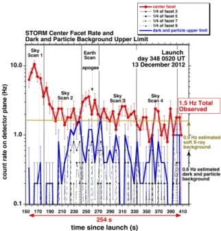
Figure 6 shows the observed DXL/STORM light curve during the DXL rocket flight. The red curve shows the light curve from the central populated facet, counts per second observed in the 20 mm x 20 mm region of the de-tector plane corresponding to the central facet averaged over five seconds. The blue curve on Figure 6 shows the estimated noise count rate upper limit due to dark cur-rent and particle counts. We estimate that this rate is about 0.6 Hz, indicated by the black arrow in the lower right of Figure 6.
This noise rate was determined by summing the rates on the detector plane from the closest (to the central
FIG. 5. Top panel: The raw DXL/STORM counts in detec-tor coordinates. Bottom panel: The DXL/STORM response during a vacuum sequence test when the instrument’s rocket section door was closed and no soft X-rays were present.
facet) 1/4 of the area of each of the four corner facets (those that share a corner with the central facet and are shielded behind aluminum blanks - see the small squares in the top panel of Figure 5). These are plotted as the light curves using black lines in Figure 6. Because of the cruciform arms from single reflections and the low-intensity diffuse region, the point spread function from X-rays that nominally hit the detector plane behind active facets can extend into areas on the detector plane that are behind blanked facets.39 These are real X-rays that
can, in principle, create a response behind blanked-off facets so that this rate is truly an upper limit on the noise level.
As can be seen in Figure 6, the observed DXL/STORM count rate over the entire rocket flight was about 1.5 Hz. This rate is consistent with a 0.9 Hz rate due to soft X-rays and a 0.6 Hz background rate, as illustrated by the black and brown arrows at the lower right of Figure 6.
During rocket flights, the background rate typi-cally increases with increasing altitude. Note that for DXL/STORM, the maximum dark and particle rate oc-curs near apogee around 250-270 seconds into the flight. Because DXL/STORM had no vetoing detectors to elim-inate events due to penetrating particles, the variation
FIG. 6. The observed DXL/STORM light curve during the DXL flight. Sky scan 1 crossed a soft X-ray source at about 160 s.
in background we observe is consistent with the varia-tion in particle flux during the flight with a maximum near apogee.
VI. SPATIAL IMAGING
Although the populated side facet discussed above was only partially sensitive, the data collected from this facet have been compared to those from the central populated facet. The data from these two facets are qualitatively similar, although the side facet count rate is a factor of five or so lower.
During sky scan one, a source of soft X-rays was ob-served by both the central and side facets. The peak rate of this source occurs later in the side facet than in the central facet. Furthermore, the centroid of the soft X-ray photons over this period shows systematic motion towards the side facet. During this period, the DXL FOV was moving from north toward the south ecliptic to scan through the helium focusing cone. The side facet was located on the north side of the central facet, so that this behavior is consistent with a spatially coherent station-ary source moving through the DXL/STORM FOV from the central facet to the side facet as the rocket rotated toward the south ecliptic. The magnitude and rate of the observed source’s angular motion is also consistent with this interpretation.
Using orbit and attitude calculations supplied by Wallops Flight Facility, each photon observed by DXL/STORM over the course of the rocket flight was converted from instrument coordinates into sky coordi-nates (right ascension and declination) so that the count
rates from similar regions of the sky can be compared di-rectly. Some of the difficulties inherent in this comparison include: (i) the orbit and attitude calculations have an estimated absolute accuracy of about ±1◦ in each axis, although the repeatability of the measurements has an expected accuracy of less than 0.2◦over the course of the entire flight (due to gyro drift), (ii) the scanning of the DXL rocket results in low statistics from any given region of the sky, (iii) there could have been some motion of the DXL/STORM instrument relative to its rocket section due to causes like non-perfectly rigid mounts and ther-mal shifts as the payload heats up and cools over time in flight, (iv) a non-uniform rotation rate could cause in-tegration times to vary between scans and within scans, and (v) the putative DXL/STORM look direction may be off due to uncertainties in the mechanical mounting of the instrument, that is misalignment of DXL/STORM both internally and externally.
In spite of these challenges, Figure 7 shows the events per pixel from similar regions of the sky in right ascension and declination for sky scan one (y-axis) and sky scan two (x-axis). The data are from the region of the sky having good observational overlap during the two sky scans, constituting eleven pixels, each of which is 1 degree in right ascension and 0.5 degrees in declination. The correlation between the counts is 0.66 with a slope of 0.87, not unreasonable given the statistical uncertainty inherent in the number of counts in each pixel. Thus, in spite of the concerns listed above, the observations are consistent with DXL/STORM observing the same overall structure on the ∼1◦ pixel level during sky scan two as it did during sky scan one.
The data shown in Figure 7 are from the region of the sky from about 159◦-165◦right ascension and about 19◦-24◦ declination. The region was away from the scan endpoints and the rocket rotation was relatively con-stant during this period (∼0.77◦/s), so each pixel has roughly the same integration time. An examination of the ROSAT R12 band (0.111-0.284 keV) sky map in this region shows a non-uniformity of ∼50% in the soft X-ray surface brightness exclusive of point sources. (We have examined the point sources in this region of the sky from the RASS catalog,40 and none of these point
sources appears to be strong enough to be observable by DXL/STORM.) However, there are other effects such as SWCX contributing to the scatter seen in Figure 7, so how much of the correlation external to the detector seen in Figure 7 can be attributed to the soft X-ray back-ground is uncertain.
VII. CONCLUSION
Preliminary results from the DXL/STORM flight dis-cussed here indicate: (1) the magnitude of the observed count rate is consistent with our pre-flight expectations based on the instrument look direction and the intensity of the soft X-ray background in this direction. Because
8
FIG. 7. The correlation between sky scan one and sky scan two events observed coming from the same regions of the sky. The eleven regions of the sky used are 1◦in right ascension and 0.5◦in declination.
DXL/STORM was viewing through the flank of the mag-netosheath, the observed signal was not, and was not expected to be, dominated by magnetosheath SWCX, although it is almost certain some of the observed sig-nal is from this source. For example, Figure 5 in Collier et al.18 suggests that viewing perpendicular to the sun-earth line, as DXL/STORM was, the exospheric SWCX contribution can be a non-negligible fraction of the soft X-ray background. (2) From a comparison between the two populated facets as well as a statistical analysis cor-relating the counts observed in the same region of the sky between sky scan one and sky scan two, DXL/STORM did image structure in the observed soft X-rays.
Based on these results, it is clear that a wide FOV soft X-ray imager using the DXL/STORM design would successfully observe the intense magnetosheath and cusp SWCX soft X-ray emission present on the earth’s dayside. For example Robertson et al.7Figure 4, right panel, sug-gests that for average solar wind conditions, the SWCX soft X-ray emission from the nose is at least twice that from the flank while the cusp emission is about twice the emission from the nose.
The development of a flight-proven prototype wide FOV soft X-ray camera represents an important mile-stone in establishing a global magnetosheath, cusp, and solar wind-planetary interaction imaging capabil-ity. The DXL/STORM instrument demonstrates proof-of-concept for a full-scale mission to study SWCX. Mean-while, we look forward to a soft X-ray camera play-ing a central role on a future spacecraft, such as ESA’s AXIOM.30 Recently, the European Space Agency and the Chinese Academy of Sciences recommended the Solar
wind Magnetosphere Ionosphere Link Explorer (SMILE) as their candidate for a collaborative science mission with an anticipated launch in 2021. SMILE includes a wide field-of-view soft X-ray imager using Lobster-Eye optics to globally image the terrestrial magnetosheath.
ACKNOWLEDGMENTS
Thanks to the Wallops Flight Facility and White Sands Missile Range personnel who supported the DXL mis-sion, including DXL/STORM vibration testing, and were so generally helpful for DXL/STORM. Special thanks to Paul Rozmarynowski for mechanical design support, Kenneth Simms for assembly support, and Norman Dob-son for GSE support. Also thanks to Steve Brown in the GSFC radiation facility for support for the pro-ton beam testing and to Dan McCammon for pointing out useful references. The flight instrument develop-ment described in this paper was funded through the Planetary, Heliophysics, and Astrophysics Divisions at GSFC through Goddard’s Internal Research and Devel-opment (IRAD) program. D.K. acknowledges financial support for her activity through the program “Soleil H´eliosph`ere Magn´etosph`ere” of the French space agency CNES and the National Program “Physique Chimie du Milieu Interstellaire” of the Institut National des Sciences de l’Univers (INSU).
1K. Kuntz, Y. Collado-Vega, M. Collier, H. Connor, T. Cravens,
D. Koutroumpa, F. Porter, I. Robertson, D. Sibeck, S. Snowden, N. Thomas, and B. Walsh, Astrophys. J., in review , yyy (2015).
2T. E. Cravens, Geophys. Res. Lett. 24, 105 (1997).
3D. G. Sibeck, G. Paschmann, R. A. Treumann, S. A.
Fuse-lier, W. Lennartsson, M. Lockwood, R. Lundin, K. W. Ogilvie, T. G. Onsager, T.-D. Phan, M. Roth, M. Scholer, N. Sckopke, K. Stasiewicz, and M. Yamauchi, Space Sci. Rev. 88, 207 (1999).
4M. R. Collier, D. G. Sibeck, T. E. Cravens, I. P. Robertson, and
N. Omidi, EOS Transactions 91, 213 (2010).
5J. A. Carter, S. Sembay, and A. M. Read, MNRAS 402, 867
(2010), arXiv:0911.0897 [astro-ph.HE].
6J. A. Carter, S. Sembay, and A. M. Read, A&A 527, A115
(2011), arXiv:1101.1848 [astro-ph.IM].
7I. P. Robertson, M. R. Collier, T. E. Cravens, and M.-C. Fok,
Journal of Geophysical Research (Space Physics) 111, A12105 (2006).
8R. Wegmann and K. Dennerl, Astron. Astrophys. 430, L33
(2005).
9C. Lisse, K. Dennerl, J. Englhauser, M. Harden, F.
Mar-shall, M. Mumma, R. Petre, J. Pye, M. Ricketts, J. Schmitt, J. Tr¨umper, and R. West, Science 274, 205 (1996).
10R. Wegmann, K. Dennerl, and C. Lisse, Astron. Astrophys. 428,
647 (2004).
11M. Holmstr¨om, S. Barabash, and E. Kallio, Geophys. Res. Lett.
28, 1287 (2001).
12K. Dennerl, A&A 394, 1119 (2002), arXiv:astro-ph/0211215. 13H. Gunell, M. Holmstr¨om, E. Kallio, P. Janhunen, and K.
Den-nerl, Geophys. Res. Lett. 31, L22801 (2004).
14H. Gunell, M. Holmstr¨om, E. Kallio, P. Janhunen, and K.
Den-nerl, Advances in Space Research 36, 2057 (2005).
15K. Dennerl, C. M. Lisse, A. Bhardwaj, V. Burwitz, J. Englhauser,
H. Gunell, M. Holmstr¨om, F. Jansen, V. Kharchenko, and P. M. Rodr´ıguez-Pascual, A&A 451, 709 (2006).
16K. Dennerl, V. Burwitz, J. Englhauser, C. Lisse, and S. Wolk,
17K. Dennerl, Planet. Space. Sci. 56, 1414 (2008).
18M. R. Collier, S. L. Snowden, M. Sarantos, M. Benna, J. A.
Carter, T. E. Cravens, W. Farrel, S. Fatemi, H. K. Hills, R. Hodges, M. Holmstr¨om, K. D. Kuntz, F. S. Porter, A. Read, I. Robertson, S. Sembay, D. Sibeck, T. Stubbs, P. Travnicek, and B. Walsh, J. Geophys. Res.: Planets 119, 1 (2014).
19D. Koutroumpa, M. Collier, K. Kuntz, R. Lallement, and
S. Snowden, Astrophys. J. 697, 1214 (2009).
20I. P. Robertson and T. E. Cravens, Journal of Geophysical
Re-search (Space Physics) 108, 8031 (2003).
21K. Kuntz, American Institute of Physics Conference Series 1156,
3 (2009).
22A. N. Brunton, G. W. Fraser, J. E. Lees, and I. C. E. Turcu,
Appl. Opt. 36, 5461 (1997).
23G. W. Fraser, A. N. Brunton, N. P. Bannister, J. F.
Pear-son, M. Ward, T. J. StevenPear-son, D. J. WatPear-son, B. Warwick, S. Whitehead, P. O’Brian, N. White, K. Jahoda, K. Black, S. D. Hunter, P. Deines-Jones, W. C. Priedhorsky, S. P. Brumby, K. N. Borozdin, T. Vestrand, A. C. Fabian, K. A. Nugent, A. G. Peele, T. H. Irving, S. Price, S. Eckersley, I. Renouf, M. Smith, A. N. Parmar, I. M. McHardy, P. Uttley, and A. Lawrence, in X-Ray and Gamma-Ray Instrumentation for Astronomy XII, Society of Photo-Optical Instrumentation Engineers (SPIE) Conference Se-ries, Vol. 4497, edited by K. A. Flanagan and O. H. W. Siegmund (2002) pp. 115–126.
24M. Galeazzi, M. Chiao, M. R. Collier, T. Cravens,
D. Koutroumpa, K. D. Kuntz, R. Lallement, S. T. Lepri, D. Mc-Cammon, K. Morgan, F. S. Porter, I. Robertson, S. L. Snowden, N. E. Thomas, Y. Uprety, E. Ursino, and B. M. Walsh, Nature 512, 171 (2014).
25P. Kirkpatrick and A. V. Baez, Journal of the Optical Society of
America (1917-1983) 38, 766 (1948).
26G. Price, A. Brunton, M. Beijersbergen, G. Fraser, M.
Bav-daz, J.-P. Boutot, R. Fairbend, S.-O. Flyckt, A. Peacock, and E. Tomaselli, Nucl. Inst. Meth. Phys. Res. A 490, 276 (2002).
27M. R. Collier, F. S. Porter, D. G. Sibeck, J. A. Carter, M. P.
Chiao, D. J. Chornay, T. Cravens, M. Galeazzi, J. W. Keller, D. Koutroumpa, K. Kuntz, A. M. Read, I. P. Robertson, S. Sem-bay, S. Snowden, and N. Thomas, Astronomische Nachrichten 333, 378 (2012).
28G. W. Fraser, J. D. Carpenter, D. A. Rothery, J. F. Pearson,
A. Martindale, J. Huovelin, J. Treis, M. Anand, M. Anttila, M. Ashcroft, J. Benkoff, P. Bland, A. Bowyer, A. Bradley, J. Bridges, C. Brown, C. Bulloch, E. J. Bunce, U. Christensen, M. Evans, R. Fairbend, M. Feasey, F. Giannini, S. Hermann, M. Hesse, M. Hilchenbach, T. Jorden, K. Joy, M. Kaipiainen, I. Kitchingman, P. Lechner, G. Lutz, A. Malkki, K. Muinonen,
J. N¨ar¨anen, P. Portin, M. Prydderch, J. S. Juan, E. Sclater, E. Schyns, T. J. Stevenson, L. Str¨uder, M. Syrjasuo, D. Talboys, P. Thomas, C. Whitford, and S. Whitehead, Planet. Space Sci. 58, 79 (2010).
29A. Martindale, J. F. Pearson, C. Whitford, G. W. Fraser, D. A.
Rothery, D. Talboys, J. D. Carpenter, T. Stevenson, E. Bunce, R. Fairbend, J. Seguy, E. Sclater, I. Delgado, A. Dixon, J. Treis, J. M. Mas-Hesse, J. L. San Juan, K. Muinonen, C. Sawyers, C. Bulloch, and E. Schyns, in Society of Photo-Optical In-strumentation Engineers (SPIE) Conference Series, Society of Photo-Optical Instrumentation Engineers (SPIE) Conference Se-ries, Vol. 7441 (2009).
30G. Branduardi-Raymont, S. Sembay, J. Eastwood, D. Sibeck,
T. Abbey, P. Brown, J. Carter, C. Carr, C. Forsyth, D. Kataria, S. Kemble, S. Milan, C. Owen, L. Peacocke, A. Read, A. Coates, M. Collier, S. Cowley, A. Fazakerley, G. Fraser, G. Jones, R. Lallement, M. Lester, F. Porter, and T. Yeoman, Exp. As-tron. 33, 403 (2012).
31F. Jansen, D. Lumb, B. Altieri, J. Clavel, M. Ehle, C. Gabriel,
M. Guainazzi, P. Gondoin, R. Much, R. Munoz, M. Santos, N. Schartel, D. Texier, and G. Vacanti, Astron. Astrophys. 365, L1 (2001).
32C. Martin, P. Jelinsky, M. Lampton, R. Malina, and H. Anger,
Rev. Sci. Instrum. 52, 1067 (1981).
33M. Galeazzi, M. Chiao, M. R. Collier, T. Cravens,
D. Koutroumpa, K. D. Kuntz, S. Lepri, D. McCammon, F. S. Porter, K. Prasai, I. Robertson, S. Snowden, and Y. Uprety, Experimental Astronomy 32, 83 (2011), arXiv:1108.0418 [astro-ph.SR].
34M. Galeazzi, M. R. Collier, T. Cravens, D. Koutroumpa, K. D.
Kuntz, S. Lepri, D. McCammon, F. S. Porter, K. Prasai, I. Robertson, S. Snowden, N. E. Thomas, and Y. Uprety, As-tronomische Nachrichten 333, 383 (2012).
35J. A. Carter and S. Sembay, A&A 489, 837 (2008),
arXiv:0807.3624.
36T. E. Cravens, I. P. Robertson, and S. L. Snowden, J. Geophys.
Res. 106, 24883 (2001).
37K. Kuntz and S. Snowden, Astrophys. J. 543, 195 (2000). 38S. Pearce, J. Lees, J. Pearson, G. Fraser, A. Brunton, K.
Flana-gan, A. Kenter, M. Barbera, V. Dhanak, A. Robinson, and D. Teehan, SPIE 2518, 322 (2010).
39J. K. Black, A. N. Brunton, N. P. Bannister, P. Deines-Jones,
and K. Jahoda, Nucl. Inst. Meth. Phys. Res. A 513, 123 (2003).
40W. Voges, B. Aschenbach, T. Boller, H. Br¨auninger, U. Briel,
W. Burkert, K. Dennerl, J. Englhauser, R. Gruber, F. Haberl, G. Hartner, G. Hasinger, M. K¨rster, E. Pfeffermann, W. Pietsch, P. Predehl, C. Rosso, J. Schmitt, J. Tr¨umper, and H. Zimmer-man, Astron. Astrophys. 349, 389 (1999).