Publisher’s version / Version de l'éditeur:
Vous avez des questions? Nous pouvons vous aider. Pour communiquer directement avec un auteur, consultez la première page de la revue dans laquelle son article a été publié afin de trouver ses coordonnées. Si vous n’arrivez pas à les repérer, communiquez avec nous à PublicationsArchive-ArchivesPublications@nrc-cnrc.gc.ca.
Questions? Contact the NRC Publications Archive team at
PublicationsArchive-ArchivesPublications@nrc-cnrc.gc.ca. If you wish to email the authors directly, please see the first page of the publication for their contact information.
https://publications-cnrc.canada.ca/fra/droits
L’accès à ce site Web et l’utilisation de son contenu sont assujettis aux conditions présentées dans le site
LISEZ CES CONDITIONS ATTENTIVEMENT AVANT D’UTILISER CE SITE WEB.
Inter-Noise 2007 [Proceedings], pp. 1-9, 2007-08-28
READ THESE TERMS AND CONDITIONS CAREFULLY BEFORE USING THIS WEBSITE.
https://nrc-publications.canada.ca/eng/copyright
NRC Publications Archive Record / Notice des Archives des publications du CNRC :
https://nrc-publications.canada.ca/eng/view/object/?id=6cb314cd-06ec-45ed-8e43-7c766cf14726 https://publications-cnrc.canada.ca/fra/voir/objet/?id=6cb314cd-06ec-45ed-8e43-7c766cf14726
NRC Publications Archive
Archives des publications du CNRC
This publication could be one of several versions: author’s original, accepted manuscript or the publisher’s version. / La version de cette publication peut être l’une des suivantes : la version prépublication de l’auteur, la version acceptée du manuscrit ou la version de l’éditeur.
Access and use of this website and the material on it are subject to the Terms and Conditions set forth at On a semi-empirical approach to predicting sound insulation in lightweight framed construction
http://irc.nrc-cnrc.gc.ca
O n a s e m i - e m p i r i c a l a p p r o a c h t o p r e d i c t i n g
s o u n d i n s u l a t i o n i n l i g h t w e i g h t f r a m e d
c o n s t r u c t i o n
N R C C - 4 9 5 0 5
Q u i r t , J . D . ; N i g h t i n g a l e , T . R . T .
A version of this document is published in / Une version de ce document se trouve dans: Inter-Noise 2007, Istanbul, Turkey, August 28-31, 2007, pp. 1-9
The material in this document is covered by the provisions of the Copyright Act, by Canadian laws, policies, regulations and international agreements. Such provisions serve to identify the information source and, in specific instances, to prohibit reproduction of materials without written permission. For more information visit http://laws.justice.gc.ca/en/showtdm/cs/C-42
Les renseignements dans ce document sont protégés par la Loi sur le droit d'auteur, par les lois, les politiques et les règlements du Canada et des accords internationaux. Ces dispositions permettent d'identifier la source de l'information et, dans certains cas, d'interdire la copie de documents sans permission écrite. Pour obtenir de plus amples renseignements : http://lois.justice.gc.ca/fr/showtdm/cs/C-42
INTER-NOISE 2007
28-31 AUGUST 2007 ISTANBUL, TURKEY
On a semi-empirical approach to predicting sound insulation
in lightweight framed construction
J.D. Quirta, T.R.T. Nightingaleb
Institute for Research in Construction National Research Council Canada,
Ottawa, K1A 0R6
CANADA
ABSTRACT
Predicting the apparent airborne and impact sound insulation of lightweight framed constructions is very challenging, particularly if the approach is to be sufficiently simple for standardization. There are two basic approaches – semi-empirical or statistical energy analysis (SEA). The SEA approach is considered in an associated InterNoise 2007 paper entitled, “Measurement and prediction of flanking transmission through gypsum board walls with modified SEA method”. This paper explores the strengths and weaknesses of the semi-empirical approach by considering flanking involving the wall/floor junction as an example. Flanking path power flow is defined by five transmission factors whose combined effect is characterized by a path transfer function specific to the type of excitation (airborne or impact) and the construction detail. For similar constructions, path estimates are obtained by adding a correction to account for the mounting, number, and type of layers of the flanking surface. Unfortunately, to deal with junction attenuation, a unique transfer function is required for each major type of structural framing at the junction (i.e., joist orientation and continuity). Relatively few transfer functions are required to accurately predict a large number of practical construction scenarios including the effect of toppings on floors and the mounting of the gypsum board on walls and ceilings.
1 INTRODUCTION
This paper reports results from continuing studies of sound transmission between adjacent units in wood-framed multi-dwelling buildings. It combines a discussion of principles for predicting the performance with some recent extensions of our multi-year experimental study, which has assessed how common construction details affect structure-borne (flanking) transmission between adjacent rooms, for a broad range of wall and floor constructions.
Previous reports have focused on the wall and floor surfaces connected at the wall/floor junction - especially the floor surface, which is often the dominant problem. This paper includes a number of other paths that may collectively become significant when more obvious paths are controlled.
Estimates of apparent sound insulation were obtained by summing the energy transmitted directly through the separating wall or floor assembly with that for all the flanking paths involving wall, floor, or ceiling surfaces abutting the separating assembly. These estimates provide the basis for a simplified design guide [1] to predict sound insulation in typical wood-framed row housing or apartment buildings. The Guide presents the sound insulation
a
Email address: Dave.Quirt @nrc.gc.ca
b
using ASTM ratings; for the international audience of this conference, the performance is recast in terms of the equivalent ISO ratings, as Apparent Sound Reduction Index, R´w.
This paper focuses mainly on a subset of the results for airborne sources and horizontal transmission, for wood-framed constructions with the wall and floor assemblies shown in Figure 1, or minor variants on them. Construction specifications, AutoCAD detail drawings, and references to pertinent technical standards, and procedures are given elsewhere [2].
(a)
(a) (b)(b) (c)(c) (d)(d)
Figure 1: Construction details of the 4 basic wall/floor systems discussed in this paper. For the separating wall with single wood studs, joists were oriented (a) parallel to the wall, (b) perpendicular to the wall, and (c) perpendicular to the wall and continuous across it. Joists are perpendicular to the double stud wall in (d).
2 THE SEMI-EMPIRICAL APPROACH
In this approach, the power flow via each flanking path is defined by five transmission factors whose combined effect is characterized by a path transfer function specific to the type of excitation (airborne or impact) and the construction detail. In previous papers [3,4] this has been discussed extensively in the context of impact sources, as illustrated in Figure 2. The resulting vibration levels across the floor surface are illustrated in Figure 3, for one position of a standard tapping machine on the floor of construction (d) with floor joists perpendicular to the separating wall between two side-by-side rooms.
2. Attenuation with Distance 1. Power injected by source depends on Impedance match 3. Junction Attenuation 5. Flanking sound power depends on radiation impedance 4. Structural Attenuation 1 2 3 5 4 4 5 2. Attenuation with Distance 1. Power injected by source depends on Impedance match 3. Junction Attenuation 5. Flanking sound power depends on radiation impedance 4. Structural Attenuation 1 1 2 2 33 55 4 4 4 4 4 5 5
Figure 2: Five factors that affect flanking transmission, with an impact source
80 78 76 74 72 82 70 86 88 68 92 66 94 96 70 66 98 70 100 Impact source Separating wall Plan view of floor surface Floor joists 80 78 76 74 72 82 70 86 88 68 92 66 94 96 70 66 98 70 100 80 78 76 74 72 82 70 86 88 68 92 66 94 96 70 66 98 70 100 Impact source Separating wall Plan view of floor surface Floor joists
Clearly the system is anisotropic and highly damped – the vibration field exhibits a strong gradient that is different in the directions parallel and perpendicular to the joists. In general, this vibration field is a poor approximation of a diffuse field, which limits the applicability of SEA models. A general model for such a system should account for all five factors indicated in Figure 2, for a range of source positions representative of typical use.
Essentially the same five factors apply to characterizing the propagation with an airborne source, as indicated in Figure 4. With an airborne source, the effect of source position is largely eliminated because there is fairly uniform incident sound power on the surfaces of the room, but all five factors still affect the sound power reaching the receiving room via a flanking path such as the floor-floor path illustrated in Figure 4. Changing construction details will alter one or more factors. Specific examples of the effect due to common variations in construction are presented and discussed in the next section.
2. Attenuation with Distance 1. Power injected from airborne source depends on impedance 3. Junction Attenuation
5. Flanking sound power depends on radiation impedance 4. Structural Attenuation 2 3 5 4 4 5 Direct Transmission 2. Attenuation with Distance 1. Power injected from airborne source depends on impedance 3. Junction Attenuation
5. Flanking sound power depends on radiation impedance 4. Structural Attenuation 2 2 33 55 4 4 4 4 5 5 Direct Transmission
Figure 4: Five factors that affect flanking transmission, with an airborne source
3 RESULTS AND DISCUSSION
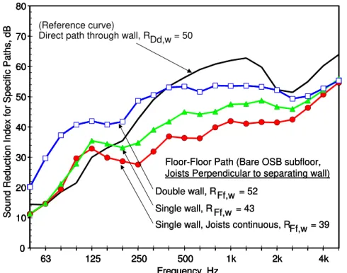
The effect of changing just the junction attenuation (factor 3) is illustrated in Figure 5 for the floor-floor path of three constructions where the other factors are essentially constant.
Dd,W = 50 0 10 20 30 40 50 60 70 80 63 125 250 500 1k 2k 4k Frequency, Hz Soun d R eduction Index for Specific Paths, dB Double wall, RFf,w = 52 Single wall, R Ff,w = 43
Single wall, Joists continuous, RFf,w = 39 Floor-Floor Path (Bare OSB subfloor, Joists Perpendicular to separating wall) (Reference curve)
Direct path through wall, RDd,w = 50Dd,W = 50
0 10 20 30 40 50 60 70 80 63 125 250 500 1k 2k 4k Frequency, Hz Soun d R eduction Index for Specific Paths, dB Double wall, RFf,w = 52 Single wall, R Ff,w = 43
Single wall, Joists continuous, RFf,w = 39 Floor-Floor Path (Bare OSB subfloor, Joists Perpendicular to separating wall) (Reference curve)
Direct path through wall, RDd,w = 50Dd,W Dd,W = 50= 50
0 10 20 30 40 50 60 70 80 0 10 20 30 40 50 60 70 80 63 125 250 500 1k 2k 4k Frequency, Hz 63 125 250 500 1k 2k 4k Frequency, Hz Soun d R eduction Index for Specific Paths, dB Double wall, RFf,w = 52 Single wall, R Ff,w = 43
Single wall, Joists continuous, RFf,w = 39 Double wall, RFf,w = 52
Single wall, R Ff,w = 43
Single wall, Joists continuous, RFf,w = 39 Floor-Floor Path (Bare OSB subfloor, Joists Perpendicular to separating wall) Floor-Floor Path (Bare OSB subfloor, Joists Perpendicular to separating wall) (Reference curve)
Direct path through wall, RDd,w = 50
Because all floors in Figure 5 have joists perpendicular to the wall and the same top surface of wood oriented strandboard (OSB), factors such as attenuation across the floor and radiation impedance for the floor-floor paths should be the same. However, the three junctions are very different; construction (c) with the joists continuous across the junction provides the strongest connection across the junction, and hence the lowest sound reduction index for the floor-floor path.
The solid black curve in Figure 5 is the sound reduction index for direct transmission through the separating wall of constructions (a) to (c); this is used as a reference curve in subsequent figures, to facilitate comparisons.
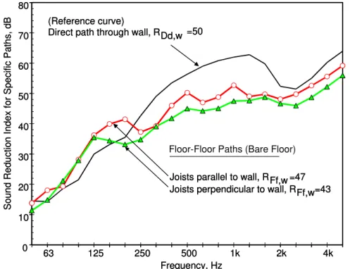
The comparison in Figure 5 is unusual, in the sense that one of the five factors can be uniquely associated with a change in construction. Usually, construction changes affect several factors. For example, the change in attenuation via floor-floor paths in Figure 6 for constructions (a) and (b) shows the combined effect of changing attenuation across the floor due to different joist orientation, and changing the junction attenuation.
Despite some uncertainty due to the change in junction details, the difference between the path attenuations with the two joist orientations is consistent with the expectation of higher attenuation with the joists parallel to the wall, due to the greater losses across the floor (factors 2 and 4). For airborne sound, the effect of changing joist orientation is much less pronounced than for impact sound, where the effect is quite large for a localized source several metres from the wall.
0 10 20 30 40 50 60 70 80 63 125 250 500 1k 2k 4k Frequency, Hz Sou nd Red uctio n In dex fo r Sp ecific Pa ths, d B
Joists parallel to wall, RFf,w =47 Joists perpendicular to wall, RFf,w=43 Floor-Floor Paths (Bare Floor) (Reference curve)
Direct path through wall, RDd,w =50
0 10 20 30 40 50 60 70 80 63 125 250 500 1k 2k 4k Frequency, Hz Sou nd Red uctio n In dex fo r Sp ecific Pa ths, d B
Joists parallel to wall, RFf,w =47 Joists perpendicular to wall, RFf,w=43 Joists parallel to wall, RFf,w =47 Joists perpendicular to wall, RFf,w=43 Floor-Floor Paths (Bare Floor) (Reference curve)
Direct path through wall, RDd,w =50 (Reference curve)
Direct path through wall, RDd,w =50
Figure 6: Sound reduction index for specific paths for constructions (a) and (b) of Figure 1.
Note that for the constructions (a) to (c), the floor-floor path transmits far more energy than paths involving the wall over most of the frequency range, and hence flanking dominates the transmission.
One obvious method to reduce transmission via the floor-floor path is to add a floor topping or covering. Locally reacting layers such as a carpet affect the impedance and – to a lesser extent – attenuation across the floor, but the effect is much less for an airborne source than an impact source. However, stiffer and heavier materials that react non-locally can
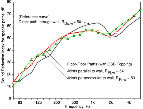
significantly change both radiation impedance and the attenuation across the floor. As an example, the path attenuations with a topping of 16 mm OSB are shown in Figure 7; comparing with Figure 6 shows the improvement. Heavier toppings such as a layer of concrete bonded to the subfloor, or concrete on a resilient mat, provide even more improvement for airborne sources.
Unfortunately, the change in flanking due to a topping depends not just on the topping but also on the floor system upon which it is applied. Hence a prediction model where the incremental effect of a given lining can be characterized by a single curve is not feasible – each topping must be evaluated on a representative set of floor assemblies. Further, the changes due to a topping are not the same for direct and flanking transmission.
0 10 20 30 40 50 60 70 80 63 125 250 500 1k 2k 4k Frequency, Hz
Sound Reduction Index
for
specific paths, dB
(Reference curve)
Direct path through wall, RDd,w= 50
Joists parallel to wall, RFf,w = 54 Joists perpendicular to wall, RFf,w = 53 Floor-Floor Paths (with OSB Topping)
0 10 20 30 40 50 60 70 80 63 125 250 500 1k 2k 4k Frequency, Hz
Sound Reduction Index
for
specific paths, dB
(Reference curve)
Direct path through wall, RDd,w= 50
Joists parallel to wall, RFf,w = 54 Joists perpendicular to wall, RFf,w = 53 Floor-Floor Paths (with OSB Topping)
Figure 7: Sound reduction index for specific paths, for constructions (a) and (b) of Figure 1 with the addition of a second layer of OSB stapled on top of the basic subfloor.
As shown in Figure 7, adding a topping over the subfloor increases the sound reduction index for this path to the point where it transmits less than the separating wall; other toppings would provide even greater attenuation of the flanking via the floor. This increases overall apparent sound reduction, R´w, and even greater improvement could be obtained by also
improving the separating wall. However, when attenuation for the floor-floor path is improved, other paths become significant - two obvious paths of concern involve the ceiling and the abutting walls.
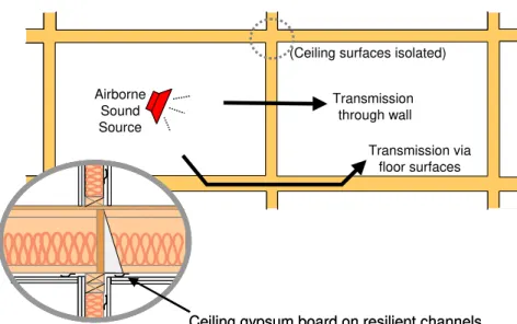
In one-level apartments, as illustrated in Figure 8, the gypsum board ceiling is normally mounted on resilient channels (to enhance airborne and impact sound insulation from the apartment above).
This also reduces flanking transmission between the side-by-side units via the ceiling-ceiling path to insignificance (as discussed in more detail below).
Transmission via floor surfaces (Ceiling surfaces isolated)
Transmission through wall Airborne Sound Source Transmission via floor surfaces (Ceiling surfaces isolated)
Transmission through wall Airborne
Sound Source
Ceiling gypsum board on resilient channels Ceiling gypsum board on resilient channels
Figure 8: Typical transmission paths between adjacent one-level apartment units. The walls parallel to the plane of this figure (side walls) also transmit sound, but resilient channels supporting
gypsum board of the ceiling suppress transmission via ceiling-ceiling path.
Figure 9 shows the average flanking via an abutting sidewall with one layer of gypsum board fastened directly to the framing. This path transmits relatively little sound (RFf,w 61 for
one wall in the construction tested), but this could also limit overall performance if the separating wall and the floor were improved (and if there were two such walls, their combined RFf,w would be 3 dB lower).
0 10 20 30 40 50 60 70 80 63 125 250 500 1k 2k 4k Frequency, Hz Sound
Reduction Index for
Specifi
c
Paths,
dB
Ceiling paths (gypsum board direct-attached), RFf,w=52 (Reference curve)
Direct path through wall, RDd,w=50 Sidewall path (gypsum board direct-attached) RFf,w=61
0 10 20 30 40 50 60 70 80 63 125 250 500 1k 2k 4k Frequency, Hz Sound
Reduction Index for
Specifi
c
Paths,
dB
Ceiling paths (gypsum board direct-attached), RFf,w=52 (Reference curve)
Direct path through wall, RDd,w=50 Sidewall path (gypsum board direct-attached) RFf,w=61
0 10 20 30 40 50 60 70 80 63 125 250 500 1k 2k 4k Frequency, Hz Sound
Reduction Index for
Specifi
c
Paths,
dB
Ceiling paths (gypsum board direct-attached), RFf,w=52 (Reference curve)
Direct path through wall, RDd,w=50 Sidewall path (gypsum board direct-attached) RFf,w=61
0 10 20 30 40 50 60 70 80 63 125 250 500 1k 2k 4k Frequency, Hz Sound
Reduction Index for
Specifi
c
Paths,
dB
Ceiling paths (gypsum board direct-attached), RFf,w=52 (Reference curve)
Direct path through wall, RDd,w=50 Sidewall path (gypsum board direct-attached) RFf,w=61
Figure 9: Sound reduction for flanking paths not involving transmission via the wall/floor junction.
In row housing (where transmission between stories within a dwelling unit is not a concern) the ceiling would commonly be screwed directly to the bottom of the joists. Then the ceiling-ceiling flanking path also becomes significant, as indicated in Figure 10. The associated sound reduction index for this ceiling-ceiling path when joists are perpendicular to the separating wall is given in Figure 9.
Flanking Transmission via ceiling surfaces Transmission through wall Airborne Sound Source Flanking Transmission via floor surfaces
Flanking Transmission via floor-ceiling
Ceiling gypsum board screwed to joists
Flanking Transmission via ceiling surfaces Transmission through wall Airborne Sound Source Flanking Transmission via floor surfaces
Flanking Transmission via floor-ceiling
Flanking Transmission via ceiling surfaces Transmission through wall Airborne Sound Source Flanking Transmission via floor surfaces
Flanking Transmission via floor-ceiling
Ceiling gypsum board screwed to joists Ceiling gypsum board screwed to joists
Figure 10: Typical transmission paths in multi-level row housing.
In typical buildings, most of the room surfaces transmitting flanking sound have gypsum board surfaces – Figure 9 presents the path attenuation for two such paths, where the surface is a single layer of gypsum board attached directly to the framing. Note, however, that the flanking transmission depends on the number of layers of gypsum board and the orientation of the supporting framing, as well as on direct vs. resilient attachment to the framing.
Resilient attachment, or changing the number of layers of gypsum board, alters both radiation impedance and structural attenuation across the assembly. In general, these changes affect direct and flanking transmission differently. This has been examined experimentally for numerous specimens [2], and some typical effects have been established:
• Adding a second layer of direct-attached gypsum board typically increases direct sound transmission through gypsum board wall assemblies by 4 to 5 dB, with a broad minimum in the improvement around 1kHz. For flanking transmission, the average improvement was typically ~ 2 dB.
• For walls, the framing members (studs) are parallel to the wall/wall junction, but for ceilings the framing may be either parallel or perpendicular to the separating wall. This affects the flanking transmission; the ceiling path attenuation illustrated in Figure 9 is for the worst case; when the supporting joists of the floor above are parallel to the separating wall, less flanking via the ceiling-ceiling path is expected.
• Attaching gypsum board on resilient channels is the most effective way to change transmission. For direct transmission, the improvement is typically >15 dB at most frequencies. For flanking transmission, an improvement ~ 10 dB is more typical. However, for the sidewall and ceiling paths illustrated in Figure 9, even a 10 dB improvement makes these paths insignificant for practical purposes.
• The effect of resilient attachment is the same for source or receiving room; treating both surfaces doubles the improvement.
The estimates of flanking paths in our experimental studies were obtained by suppressing transmission via other surfaces, by masking them with a free-standing surface of gypsum board and insulation. Above ~ 400 Hz this consistently provided enough change in R’ for meaningful estimates of significant flanking paths, but at lower frequencies, the very small improvement in R’ due to the added masking surfaces limited the extraction of good
estimates. In this lower frequency range, a “tail” on the path attenuation (which decreases at 6 dB per octave below the lowest valid band) was used as a working estimate.
4 THE DESIGN GUIDE
Obviously, all paths should be considered for good design. In the Guide, tables present the combined effect of all paths for typical variants. Tables 1 and 2 show examples.
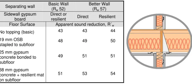
Table 1: The table gives Apparent Sound Reduction Index, R´w for “apartment design” in the case
with joists perpendicular to separating walls as shown in the drawing at right (construction (b) in Figure 1). R´w in a given building will not exactly match the tabulated values, but trends should apply.
Separating wall Basic Wall (Rw 52) Better Wall (Rw 57) Sidewall gypsum board Direct or
resilient Direct Resilient Floor Surface Apparent sound reduction, R´w
No topping (basic) 43 43 44 19 mm OSB stapled to subfloor 48 49 50 25 mm gypsum concrete bonded to subfloor 49 51 51 38 mm gypsum
concrete + resilient mat on subfloor
51 53 54
Table 2: The table gives Apparent Sound Reduction Index, R´w for “row house design” in the case
with joists perpendicular to separating walls as shown in the drawing to the right – a variant on construction (b) in Figure 1. Note the R´w values are significantly lower than corresponding values in
Table 1 due to the stronger transmission via the ceiling-ceiling path.
Separating wall Basic Wall (Rw 52) Better Wall (Rw 57) Sidewall gypsum board Direct or
resilient Direct Resilient Floor Surface Apparent sound reduction, R´w
No topping (basic subfloor) 42 43 43 19 mm OSB stapled to subfloor 47 48 48 25 mm gypsum concrete bonded to subfloor 48 49 49 38 mm gypsum
concrete + resilient mat on subfloor
49 51 51
In all cases, the overall Apparent Sound Reduction Index, R´w is lower than the Rw for the
separating wall – in some cases it is much lower. By altering design details to balance transmission via specific paths a cost-effective yet satisfactory design can be chosen.
5 SUMMARY
This paper provides a rather terse overview of how experimental characterization of the direct and flanking sound transmission paths in wood-framed construction can lead to a manageable set of path transmission terms to represent the effect of specific design tradeoffs. By combining the energy transmitted via all paths it is possible to arrive at estimates of the overall apparent sound reduction, R´w for a range of constructions. This semi-empirical
approach can provide a viable basis for design, despite the complications due to the factors inherent in each transmission path.
6 ACKNOWLEDGEMENTS
We acknowledge the support of our industry partners: CMHC, Forintek Canada, Marriott International, Owens Corning, Trus Joist, and USG. The ongoing contributions of F. King, T. Estabrooks, and B. Fitzpatrick to the experimental study are also gratefully acknowledged.
7 REFERENCES
[1] J.D. Quirt, T.R.T Nightingale, and F. King, Guide for Sound Insulation in Wood Frame Construction, RR-219, NRC-IRC, Canada, (2006)
[2] T.R.T. Nightingale, J.D. Quirt, F. King, R.E. Halliwell, Flanking Transmission in Multifamily Dwellings: Phase IV, RR-218, NRC-IRC, Canada, (2006
[3] T.R.T. Nightingale, R.E. Halliwell, J.D. Quirt, On the importance of the direct field in structure borne transmission in framed constructions, Proceedings of Forum Acusticum, Budapest, Hungary, 2005
[4] J.D. Quirt, T.R.T. Nightingale, R.E. Halliwell, Estimates of flanking paths involving the wall-floor junction in wood framed construction and included references, Proceedings of Inter-noise 2005, Rio de Janeiro, Brazil, 2005