Publisher’s version / Version de l'éditeur:
Journal of Research of the National Institute of Standards and Technology, 123,
2018-06-29
READ THESE TERMS AND CONDITIONS CAREFULLY BEFORE USING THIS WEBSITE. https://nrc-publications.canada.ca/eng/copyright
Vous avez des questions? Nous pouvons vous aider. Pour communiquer directement avec un auteur, consultez la
première page de la revue dans laquelle son article a été publié afin de trouver ses coordonnées. Si vous n’arrivez pas à les repérer, communiquez avec nous à [email protected].
Questions? Contact the NRC Publications Archive team at
[email protected]. If you wish to email the authors directly, please see the first page of the publication for their contact information.
NRC Publications Archive
Archives des publications du CNRC
This publication could be one of several versions: author’s original, accepted manuscript or the publisher’s version. / La version de cette publication peut être l’une des suivantes : la version prépublication de l’auteur, la version acceptée du manuscrit ou la version de l’éditeur.
For the publisher’s version, please access the DOI link below./ Pour consulter la version de l’éditeur, utilisez le lien DOI ci-dessous.
https://doi.org/10.6028/jres.123.009
Access and use of this website and the material on it are subject to the Terms and Conditions set forth at
Concept to commercialization of an artifact for evaluating
three-dimensional imaging systems per ASTM E3125-17
Muralikrishnan, Bala; Rachakonda, Prem; Lee, Vincent; Shilling, Meghan;
Sawyer, Daniel; Cheok, Geraldine; Cournoyer, Luc; Gleason, Joe
https://publications-cnrc.canada.ca/fra/droits
L’accès à ce site Web et l’utilisation de son contenu sont assujettis aux conditions présentées dans le site LISEZ CES CONDITIONS ATTENTIVEMENT AVANT D’UTILISER CE SITE WEB.
NRC Publications Record / Notice d'Archives des publications de CNRC:
https://nrc-publications.canada.ca/eng/view/object/?id=4325775c-6eae-4089-883a-4dbf2ca587f4 https://publications-cnrc.canada.ca/fra/voir/objet/?id=4325775c-6eae-4089-883a-4dbf2ca587f41 How to cite this article:
Concept to Commercialization of an Artifact
for Evaluating Three-Dimensional Imaging
Systems per ASTM E3125-17
Bala Muralikrishnan1, Prem Rachakonda1, Vincent Lee1, Meghan Shilling1, Daniel Sawyer1, Geraldine Cheok1, Luc Cournoyer2, and Joe Gleason3
1National Institute of Standards and Technology, Gaithersburg, MD 20899, USA
2National Research Council of Canada, Ottawa, Ontario K1A 0R6, Canada 3Bal-tec Inc.,
Los Angeles, CA 90011, USA
[email protected], [email protected], [email protected], [email protected], [email protected], [email protected], [email protected], [email protected]
Summary:
• The relative-range error test is one of several tests described in the ASTM E3125-2017 standard for performance evaluation of spherical coordinate three-dimensional (3D) imaging systems such as terrestrial laser scanners (TLS). We designed a new artifact, called the plate-sphere target, that allows the realization of the relative-range error tests quickly and efficiently without the need for alignment at each position of the test.
• Use of a simple planar/plate target requires careful alignment of the target at each position of the relative-range error test, which is labor-intensive and time-consuming. This new artifact significantly reduces the time required to perform the test, from a matter of about 2 h to less than 30 min while resulting in similar test uncertainty values.
• The plate-sphere target was conceived and initially developed at the National Institute of Standards and Technology (NIST), improved based on feedback from collaborators at the National Research Council (NRC) of Canada and TLS manufacturers, and commercialized by Bal-tec Inc.
• This new artifact will save users and manufacturers of TLSs considerable time and money.
Key words: ASTM E3125-17; laser scanner; plate-sphere artifact; relative-range error test.
Accepted: May 18, 2018
Published: June 29, 2018
https://doi.org/10.6028/jres.123.009
1.
Challenge
The newly released ASTM E3125-17 [1] standard describes several point-to-point distance tests that can be used to evaluate the performance of spherical coordinate three-dimensional (3D) imaging systems,
Volume 123, Article No. 123009 (2018) https://doi.org/10.6028/jres.123.009
Journal of Research of the National Institute of Standards and Technology
2 https://doi.org/10.6028/jres.123.009
commonly referred to as terrestrial laser scanners (TLS).1 The relative-range error test, which is one of several tests described in that standard, is a point-to-point distance test conducted along the ranging direction of the scanner to evaluate the distance measurement errors of the scanner. This test involves the determination of the distance between a planar target placed at two positions, a reference position and a test position, along the ranging direction of the scanner by both the TLS and a reference instrument. Because the simple planar/plate target requires careful alignment of the target at each position of the test, this is labor-intensive and time-consuming for users and manufacturers of TLSs.
In this paper, we consider a laser tracker (LT) as the reference instrument. A LT is also a spherical coordinate measurement system, where a ranging unit is mounted on a two-axis gimbal. The instrument measures the range and two angles to a spherically mounted retroreflector (SMR) target. The ranging unit is generally based on interferometry or absolute distance measurement technology and can provide range measurements with uncertainties of typically less than 10 µm over 60 m, which is an order of magnitude smaller than the range uncertainties expected of TLS systems [2,3]. It should be noted that while the TLS reduces thousands of points acquired on the plate surface to a single point, this only reduces the influence of random errors in the TLS range. The TLS is expected to have large systematic errors in its range, so an LT measurement based on a single point will still produce measurements with small enough uncertainty to provide a reference measurement for the TLS.
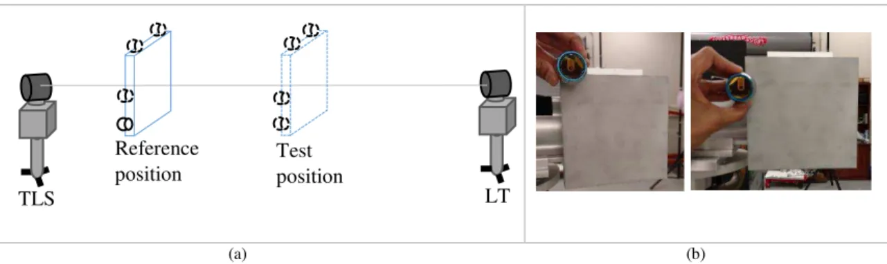
The ASTM E3125-17 standard mandates three distances determined from the reference position of the target. There are, therefore, four different target positions involved, one reference and three test positions. Figure 1 shows one way of realizing the relative-range error test with the reference and test positions located between the TLS and the LT. The TLS scans the front surface of the plate target at each of the reference and test positions, and the center of the plate is determined from the corresponding point cloud data. The distance between the center of the plate at the two positions is the test distance. At each of the reference and test positions, the outer boundary of the plate target is probed by an SMR that is locked on to an LT, to establish the center of the target. The distance between the center of the plate as determined by the LT at the two positions is the reference distance. The error in the displacement, which is the difference between the distance determined by the TLS and the LT, must be smaller than the manufacturer-specified limits to pass the test.
(a) (b)
Fig. 1. Setup for a relative-range error test using a flat plate target. (a) The outer boundary of the plate target is probed using an SMR to establish the center for reference length calculation. (b) Photo of the target and SMR used to probe outer boundary of the target.
If the TLS and the LT do not measure the same point on the plate, errors are introduced into the measurement, thereby increasing the test value uncertainty; these errors increase as the alignment deviates. It is generally very challenging to measure the same point by both the TLS and the LT without
distinguishing features or fiducials that can be used to locate that point. To reduce the impact of this
1 Certain commercial equipment, instruments, or materials are identified in this paper to foster understanding. Such identification does not imply recommendation or endorsement by the National Institute of Standards and Technology, nor does it imply that the materials or equipment identified are necessarily the best available for the purpose.
LT Reference position Test position TLS
problem, the test is performed by aligning the plate target with the measurement axis (an imaginary line joining the origin of the LT and the TLS in Fig. 1) at the reference and test positions. Aligning the plate target (shown in Fig. 1) is a considerable challenge (see Ref. [4]) because orienting the plate requires repeated measurements on the outer boundary of the plate, which are very time-consuming (about 2 h) and labor-intensive.
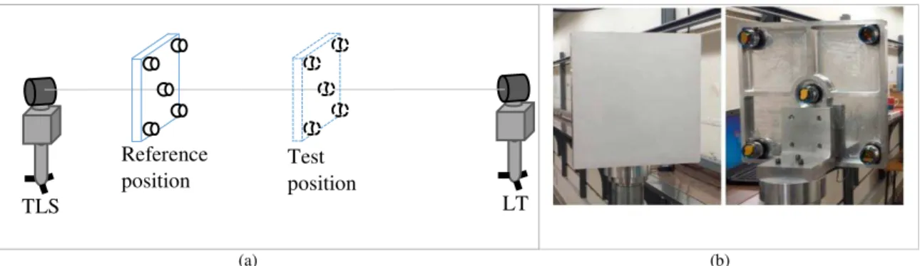
To facilitate the reference measurement and the alignment process, we developed a modified plate target at the National Institute of Standards and Technology (NIST), which we refer to as the first prototype plate target (Fig. 2). This target has five SMRs mounted on the back of the target. The SMR at the center of the target is used to ensure that the plate is on the measurement axis at each of the reference and test positions. Three of the remaining four SMRs (or all four) are used to align the plate so that it is
perpendicular to the measurement axis. Because this centering and alignment must be performed at all four positions (one reference and three test positions), this process, while an improvement from the previous setup, is still labor-intensive and time-consuming.
(a) (b)
Fig. 2. (a) First prototype of a plate target with five SMRs on the back side that are used to center and align the plate to the measurement axis. (b) Photos of the target's front side for TLS measurement and back side with an SMR at the center for LT measurement and corner SMRs for alignment purposes.
2.
Solution
To perform this test more efficiently, we devised a method to add fiducials to the plate target to allow a common point to be measured by both the TLS and the LT, thus avoiding the need to align the plate perpendicular to the measurement axis and centered on that axis. Our second prototype plate target was designed using a 100 mm diameter, commercially available “integration sphere” mounted at the center of a square plate with side dimensions of 457.2 mm (18 in.) in such a manner that the center of the sphere lies on the front surface of the plate; see Fig. 3(a). The integration sphere is a hollow partial sphere with a kinematic nest inside that allows an SMR to be centrally seated so that the center of the SMR is coincident with the center of the outer spherical shell of the integration sphere. The design allows the LT to measure the center of the SMR from the back side of the plate while the TLS measures both the sphere and the plate surface from the front side. The center of the sphere is then projected onto the plane (obtained from a best fit of the TLS point cloud data) to obtain a point that, in theory, is coincident with the center of the SMR measured by the LT. LT Reference position Test position TLS
Volume 123, Article No. 123009 (2018) https://doi.org/10.6028/jres.123.009
Journal of Research of the National Institute of Standards and Technology
4 https://doi.org/10.6028/jres.123.009 (a) (b)
Fig. 3. Second prototype of the plate-sphere target with a 100 mm diameter integration sphere centrally mounted on a square plate with side dimensions of 457.2 mm (18 in.). (a) Target with no absorbing flock paper around the sphere. (b) Target with laser-absorbing flock paper around the sphere.
We presented this design to the ASTM E57.02 working group in February 2016 and received feedback that the data in the region on the plate around the sphere may be noisier because of secondary reflections from the sphere. Based on that feedback, we added a laser absorbing ring of black flock paper, as seen in Fig. 3(b).
During subsequent testing, we determined that some scannners were unable to acquire data from a 100 mm diameter sphere at distances beyond 20 m. We therefore built the third prototype plate-sphere target with a 200 mm diameter integration sphere centrally mounted on a large square plate with side dimensions of 609.6 mm (24 in.); see Fig. 4.
Fig. 4. Third prototype of the plate-sphere target with a 200 mm diameter integration sphere centrally mounted on a square plate with side dimensions of 609.6 mm (24 in.).
In May 2016, the NIST Dimensional Metrology Group hosted an instrument runoff [5] attended by FARO, Z+F, Leica, Trimble, API, Bal-tec, and National Research Council of Canada staff. Basis Software, Inc., supplied an instrument for this event. The purpose of the runoff was to assess the suitablity of the test procedures in the draft standard at that time, to obtain feedback, and to modify the draft standard so that the eventual standard is both useful and practical. During the runoff, we received feedback that the central region of the plate was occluded by the sphere, and therefore the test was not performed with the laser beam normal (or near normal) to the plate. Based on this feedback, we then built a fourth prototype, depicted in Fig. 5, where two 100 mm diameter integration spheres are mounted on the sides of a square plate with side dimensions of 304.8 mm (12 in.) in such a manner that the centers of the spheres lie on the plane defined by the front surface of the plate. The LT measures the centers of the SMRs in each of the two fiducial spheres shown in Fig. 5. The mean of the two center coordinates is then used in the calculation of the reference distance. The TLS measures both the plate and the spheres. The mean of the centers is projected onto the plate to determine the test distance.
Fig. 5. Fourth prototype of the plate-sphere artifact with two 100 mm diameter integration spheres mounted on the sides of a square plate with side dimensions of 304.8 mm (12 in.).
The artifact shown in Fig. 5 can be manufactured at low cost because there are no critical tolerance requirements for the lateral location of the sphere center (i.e., in-plane position of the centers) with respect to the plate.This is because the test protocol allows wide latitude in choosing the “center point,” and therefore the only important criterion is that the point identified by the TLS as the “center point” must coincide with the point identified by the LT. That issue is addressed in all versions of the artifact described in this paper.
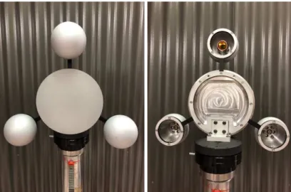
This concept of using multiple sphere fiducials outside a plate was then commercialized by Bal-tec, Inc. Their first version of this artifact (shown in Fig. 6) was presented at the annual meeting of the American Society for Precision Engineering (ASPE) in Charlotte, NC, in November 2017 (during the commerical session and in the booth). In that design, three 100 mm diameter integration spheres are mounted in the sides of a circular flat plate 177.8 mm (7 in.) in diameter. NIST was not directly involved in the design of this artifact. The addition of the third sphere helps to lower the influence of random errors in the determination of the plate center for both the LT and the TLS.
Volume 123, Article No. 123009 (2018) https://doi.org/10.6028/jres.123.009
Journal of Research of the National Institute of Standards and Technology
6 https://doi.org/10.6028/jres.123.009
3.
Benefits
• The relative-range error test is challenging to perform with a plate artifact without any fiducials. This is because the plate must be aligned to the measurement axis at the reference position and at each of the test positions. Such an alignment process is labor-intensive and time-consuming to perform.
• Our solution of using fiducial spheres on a plate ensures that both the TLS and the LT measure a common point on the plate, thus overcoming the need to carefully align the plate normal to the measurement axis.
• The relative-range error tests can be performed in less than 30 min using this new artifact, which represents a significant savings in the time and cost required to perform the test.
4.
Next Steps
Bal-tec, Inc., will continue to improve the design of this artifact based on feedback from TLS users.
5.
Partners
While the idea for this artifact was originally conceived by NIST staff, and the first prototype was fabricated at NIST, the concept benefited from extensive discussions with National Research Council of Canada staff. Further, feedback from industry partners (FARO, Leica, Z+F, Trimble, Basis Software, Bal-tec, API) who participated in the instrument runoff held at NIST in May 2016 resulted in improvements to subsequent prototypes, leading to the commercialization by Bal-tec.
6.
Learn More
More information about the development of the ASTM E3125-17 standard can be found in Ref. [5]. Information about the tec plate-sphere product may be found by contacting representatives from Bal-tec, Inc.
7.
References
[1] ASTM International (2017) ASTM E3125-17 – Standard Test Method for Evaluating the Point-to-Point Distance Measurement Performance of 3D Imaging Systems in the Medium Range (ASTM International, West Conshohocken, PA). https://doi.org/10.1520/E3125-17
[2] Cheok GS, Saidi KS, Lytle AM (2007) Evaluating a ranging protocol for 3D imaging system. Proceedings of the 24th
International Symposium on Automation and Robotics in Construction, (ISARC, Kochi, India), pp 81-87.
https://doi.org/10.22260/isarc2007/0017
[3] Ingensand H (2006) Metrological aspects in terrestrial laser-scanning technology. Proceedings of the 3rd IAG/12th FIG
Symposium (IAG/FIG, Baden, Austria). Available at
http://www.fig.net/resources/proceedings/2006/baden_2006_comm6/PDF/LS1/Ingensand.pdf
[4] Muralikrishnan B, Rachakonda P, Lee V, Shilling M, Sawyer D, Cheok G, Cournoyer L (2017) Relative range error evaluation of terrestrial laser scanners using a plate, a sphere, and a novel dual-sphere-plate target. Measurement 111:60-68. https://doi.org/10.1016/j.measurement.2017.07.027
[5] Muralikrishnan B, Rachakonda P, Shilling M, Lee V, Blackburn C, Sawyer D, Cheok G, Cournoyer L (2016) Report on the May 2016 ASTM E57.02 Instrument Runoff at NIST, Part 1 - Background Information and Key Findings. (National
Institute of Standards and Technology, Gaithersburg, MD), NIST Internal Report (NISTIR) 8152. https://doi.org/10.6028/NIST.IR.8152
About the authors: Bala Muralikrishnan is a mechanical engineer in the Engineering Physics Division at NIST. Prem Rachakonda is a mechanical engineer in the Engineering Physics Division at NIST. Vincent Lee is a mechanical engineer in the Engineering Physics Division at NIST. Meghan Shilling is a
mechanical engineer in the Engineering Physics Division at NIST. Daniel Sawyer is the group leader of the Dimensional Metrology Group at NIST. Geraldine Cheok is a research structural engineer in the
Intelligent Systems Division at NIST. Luc Cournoyer is a senior technical officer (retired) at NRC Canada. Joe Gleason is the director of engineering at Bal-tec, Inc.