HAL Id: tel-02187312
https://tel.archives-ouvertes.fr/tel-02187312
Submitted on 17 Jul 2019
HAL is a multi-disciplinary open access
archive for the deposit and dissemination of sci-entific research documents, whether they are pub-lished or not. The documents may come from teaching and research institutions in France or abroad, or from public or private research centers.
L’archive ouverte pluridisciplinaire HAL, est destinée au dépôt et à la diffusion de documents scientifiques de niveau recherche, publiés ou non, émanant des établissements d’enseignement et de recherche français ou étrangers, des laboratoires publics ou privés.
belt transmissions : Application to the Front Engine
Accessory Drive of trucks
Carlos Alexandre Ferreira Da Silva
To cite this version:
Carlos Alexandre Ferreira Da Silva. Modeling and optimization of power losses in poly-V belt transmissions : Application to the Front Engine Accessory Drive of trucks. Mechanical engineering [physics.class-ph]. Université de Lyon, 2018. English. �NNT : 2018LYSEI079�. �tel-02187312�
THESE
MODELING AND OPTIMIZATION OF POWER LOSSES IN
POLY-V BELT TRANSMISSIONS : APPLICATION TO THE
FRONT ENGINE ACCESSORY DRIVE OF TRUCKS
Présentée devant
l’Institut National de Sciences Appliquées (INSA) de Lyon
Pour obtenir
le GRADE DE DOCTEUR en GENIE MECANIQUE
Ecole Doctorale des Sciences de l’Ingénieur de Lyon :
Mécanique, Energétique, Génie Civil, Acoustique (MEGA, ED 162)
Par
Carlos Alexandre FERREIRA DA SILVA
Double diplôme d’ingénieur en Génie Mécanique
Université Fédérale d’Uberlândia (Brésil) et INSA de Lyon (France)
Soutenue le 6 Novembre 2018 devant la commission d’examen :
Jury MM.G. Parker, Robert Professeur des Universités Virginia Tech Rapporteur
Boltezar, Miha Professeur des Universités Univ of Ljubljana Rapporteur
Rémond, Didier Professeur des Universités INSA de Lyon Directeur
Manin, Lionel Maître de Conférences INSA de Lyon Co-Directeur
Michon, Guilhem Professeur des Universités ISAE Toulouse Examinateur
Baranger N., Thouraya Professeur des Universités Université Lyon 1 Examinatrice
SIGLE ECOLE DOCTORALE NOM ET COORDONNEES DU RESPONSABLE
CHIMIE CHIMIE DE LYON
http://www.edchimie-lyon.fr
Sec. : Renée EL MELHEM Bât. Blaise PASCAL, 3e étage
INSA : R. GOURDON
M. Stéphane DANIELE
Institut de recherches sur la catalyse et l’environnement de Lyon IRCELYON-UMR 5256
Équipe CDFA
2 Avenue Albert EINSTEIN 69 626 Villeurbanne CEDEX [email protected] E.E.A. ÉLECTRONIQUE, ÉLECTROTECHNIQUE, AUTOMATIQUE http://edeea.ec-lyon.fr Sec. : M.C. HAVGOUDOUKIAN [email protected] M. Gérard SCORLETTI
École Centrale de Lyon
36 Avenue Guy DE COLLONGUE 69 134 Écully
Tél : 04.72.18.60.97 Fax 04.78.43.37.17
[email protected] E2M2 ÉVOLUTION, ÉCOSYSTÈME,
MICROBIOLOGIE, MODÉLISATION
http://e2m2.universite-lyon.fr
Sec. : Sylvie ROBERJOT Bât. Atrium, UCB Lyon 1 Tél : 04.72.44.83.62 INSA : H. CHARLES
M. Philippe NORMAND
UMR 5557 Lab. d’Ecologie Microbienne Université Claude Bernard Lyon 1 Bâtiment Mendel 43, boulevard du 11 Novembre 1918 69 622 Villeurbanne CEDEX [email protected] EDISS INTERDISCIPLINAIRE SCIENCES-SANTÉ http://www.ediss-lyon.fr
Sec. : Sylvie ROBERJOT Bât. Atrium, UCB Lyon 1 Tél : 04.72.44.83.62 INSA : M. LAGARDE
Mme Emmanuelle CANET-SOULAS
INSERM U1060, CarMeN lab, Univ. Lyon 1 Bâtiment IMBL
11 Avenue Jean CAPELLE INSA de Lyon 69 621 Villeurbanne Tél : 04.72.68.49.09 Fax : 04.72.68.49.16 [email protected] INFOMATHS INFORMATIQUE ET MATHÉMATIQUES http://edinfomaths.universite-lyon.fr
Sec. : Renée EL MELHEM Bât. Blaise PASCAL, 3e étage
Tél : 04.72.43.80.46 Fax : 04.72.43.16.87 [email protected] M. Luca ZAMBONI Bât. Braconnier 43 Boulevard du 11 novembre 1918 69 622 Villeurbanne CEDEX Tél : 04.26.23.45.52 [email protected]
Matériaux MATÉRIAUX DE LYON
http://ed34.universite-lyon.fr
Sec. : Marion COMBE
Tél : 04.72.43.71.70 Fax : 04.72.43.87.12 Bât. Direction [email protected] M. Jean-Yves BUFFIÈRE INSA de Lyon MATEIS - Bât. Saint-Exupéry 7 Avenue Jean CAPELLE 69 621 Villeurbanne CEDEX
Tél : 04.72.43.71.70 Fax : 04.72.43.85.28
[email protected] MEGA MÉCANIQUE, ÉNERGÉTIQUE,
GÉNIE CIVIL, ACOUSTIQUE
http://edmega.universite-lyon.fr
Sec. : Marion COMBE
Tél : 04.72.43.71.70 Fax : 04.72.43.87.12 Bât. Direction [email protected] M. Jocelyn BONJOUR INSA de Lyon Laboratoire CETHIL Bâtiment Sadi-Carnot 9, rue de la Physique 69 621 Villeurbanne CEDEX [email protected] ScSo ScSo* http://ed483.univ-lyon2.fr
Sec. : Viviane POLSINELLI Brigitte DUBOIS
INSA : J.Y. TOUSSAINT Tél : 04.78.69.72.76 M. Christian MONTES Université Lyon 2 86 Rue Pasteur 69 365 Lyon CEDEX 07 [email protected]
To my parents who, through their efforts, allowed me to make my dreams come true.
Acknowledgments
I would like to thank God for giving me knowledge, strength, ability and opportunity to undertake this work and to persevere and complete it satisfactorily.
Thanks to my family for always standing by my side.
Thanks to LaMCoS for hosting me throughout the thesis.
Thanks to my thesis director, Didier Remond, and my thesis co-director, Lionel Manin, for giving me the opportunity to undertake this work.
I would especially like to thank my advisor, Lionel Manin, who guided me and gave me his support with patience and pedagogy throughout this professional experience.
Thanks to my teammates, Lionel Manin, Marie-Ange Andrianoely, Etienne Besnier and colleague Renaud Rinaldi, for the support and the valuable contribution.
Thanks to my interns, Xiaowen Li, Selven Ayasamy and Clement Santini for the valuable contribution and for giving me the opportunity to learn more than I might imagine.
Thanks to my fellow lab mates for the valuable discussions and moments spent in their vivacious and always stimulating company.
Thanks to Volvo Trucks for hosting us during the EDIT consortium meetings.
Thanks to Julien Ameil and Elie Garcia for providing us with support whenever required.
Thanks to the Auvergne Rhone Alpes council and Volvo Trucks who supported this work.
Abstract
This work is a part of the Efficient Distribution Truck (EDIT, FUI 19) project, led by Volvo Trucks, whose objective is to reduce distribution vehicles’ fuel consumption for 2020 by 13% when compared with the current production vehicle EURO-6. The EDIT project targets five areas of research and technical solutions, one of which consists of obtaining an optimized poly-V belt transmission concerning the power losses. In terms of life-time of the mechanical components, reduction of noise and vibrations, the Front Engine Accessory Drives (FEADs) are currently one of the most technologically sophisticated systems. However, further improvements can be made to make the vehicles more energy efficient. This thesis, which aims at investigating possibilities for reducing and optimizing the power losses in the FEADs, is composed of three main parts: the characterization of the viscoelastic materials of the poly-V belts via Dynamic Mechanical Analysis (DMA) and the FEAD components; the modeling, the optimization and the implementation of the power loss models in a simulation tool; and their experimental validation through a test bench. The power losses occurring in a FEAD are of several types: poly-V internal losses (hysteresis of the belt-rubber), poly-V external losses (belt/pulley slip) and losses from the accessory drives (friction inside the bearings). These power losses can be quanti-fied and optimized thanks to the models developed throughout this thesis. These models have been validated and implemented in a simulation tool (PLFead, Power Loss Front engine accessory drive), which has been developed to optimize the power losses taking into consideration the design parameters and operating conditions of the FEAD.
Key-words: Poly-V belt transmission. Power losses. FEAD. Optimization. Test bench.
Résumé
Ces travaux s’inscrivent dans le cadre du projet EDIT(Efficient Distribution Truck, FUI19), piloté par le groupe Volvo Trucks, dont l’objectif de réduction de consommation pour 2020 est fixé à 13% par rapport à un véhicule actuel EURO-6. Le projet EDIT porte sur cinq axes techniques d’amélioration dont un consiste en l’obtention d’un système optimisé de transmission par courroie poly-V au regard des pertes de puissance. Actuellement les faces avant de moteur sont perfectionnées sur le plan mécanique ; cela signifie que la durée de vie de ses composants est optimisée, et que les nuisances vibratoires sont réduites. Par contre, des améliorations peuvent être apportées sur le plan énergétique. Cette thèse, qui a pour objectif d’investiguer les possibilités de réduction et d’optimisation des pertes de puissance sur les façades accessoires, se décline en trois parties : une caractérisation par l’analyse mécanique dynamique des matériaux viscoélastiques des courroies poly-V et des composantes de façade ; une modélisation, une optimisation et une implémentation logi-cielle des modèles de pertes de puissance ; validées par une dernière partie expérimentale sur banc d’essais. Les pertes de puissances dans une face avant moteur sont de plusieurs types : des pertes internes à la courroie poly-V (hystérésis du caoutchouc), des pertes externes à la courroie (glissement poulie/courroie) et des pertes internes aux composants (frottement dans les roulements). Ces pertes peuvent désormais être quantifiées et op-timisées grâce aux modèles développés durant cette thèse. Ces modèles ont été validés et implémentés dans un outil de simulation (PLFead, Power Loss Front engine accessory drive), qui a été développé pour optimiser les pertes de puissance en tenant compte des paramètres de design et de fonctionnement des faces avant moteur.
Mots-clés : Transmission par courroie poly-V. Pertes de puissance. Faces avant moteur.
Optimisation. Caractérisation. Matériau viscoélastique. Modélisation. Validation sur banc d’essais. Simulation.
Resumo
Este trabalho se insere no âmbito do projeto EDIT (Efficient Distribution Truck, FUI 19), pilotado pelo grupo Volvo Trucks, cujo o objetivo de redução de consumação para 2020 é fixado em 13% em relação ao veículo atual EURO-6. O projeto EDIT se concentra em cinco áreas de pesquisa e soluções técnicas, na qual uma destas consiste na obtenção de um sistema otimizado de transmissão por correia poly-V no que diz respeito as perdas de potência. Atualmente as faces dianteiras de motores são aperfeiçoadas em relação aos seus mecanismos, isso significa que a vida útil dos seus componentes é otimizada e que o nível de vibrações é reduzido. No entanto, melhorias podem ser feitas para aumentar a eficiência enérgetica. Esta tese, que tem o objetivo de investigar possibilidades de re-dução e otimização de perdas de potência das faces dianteiras de motores, se divide em três partes : uma caracterização experimental através da análise mecânica dinâmica dos materiais viscoelásticos das correias poly-V e dos componentes de faces dianteiras de mo-tores ; uma modelagem, uma otimização e uma implementação dos modelos de perda de potência em uma ferramenta de simulação ; validadas por uma ultima parte experimental em bancada de ensaios. As perdas de potência nas faces dianteiras de motores são de vários tipos : perdas internas à correia poly-V (histerese da borracha), perdas externas à correira (escorregamento polia/correia) e perdas internas aos componentes (atrito nos rolamentos). Estas perdas de potência podem à partir de agora ser quantificadas e otimi-zadas graças aos modelos desenvolvidos durante esta tese. Estes modelos foram validados e implementados em uma ferramenta de simulação (PLFead, Power Loss Front engine accessory drive), que foi desenvolvida para otimizar as perdas de potência levando em conta paramêtros de design e de funcionamento das faces dianteiras de motores.
Palavras-chave : Transmissão por correias poly-V. Perdas de potência. Faces dianteiras
de motores. Otimização. Caracterização. Material viscoelástico. Modelagem. Validação em bancada de ensaios. Simulação.
Contents
1 INTRODUCTION 21
1.1 MOTIVATION . . . 22
1.2 LITERATURE REVIEW . . . 25
1.3 POLY-V BELT TRANSMISSION . . . 26
1.4 FRONT ENGINE ACCESSORY DRIVE . . . 27
1.5 POLY-V BELT . . . 28
1.5.1 Material . . . 28
1.5.2 Design . . . 29
1.6 ACCESSORIES . . . 30
1.6.1 Poly-V pulley . . . 31
1.6.2 Torsional Vibration Damper pulley . . . 32
1.7 TENSIONERS . . . 33
1.7.1 Idler-pulley . . . 33
1.7.2 Mechanical tensioner . . . 34
1.7.3 Hydraulic tensioner . . . 35
1.8 KEY ENTRY TOPICS . . . 36
1.8.1 Geometry . . . 36
1.8.2 Belt span tensions . . . 37
1.8.3 Belt setting tension . . . 38
1.8.4 Sliding and adhesion arcs . . . 39
1.9 OBJECTIVES . . . 41
1.10 TASK OUTLINE . . . 42
1.11 CONTRIBUTIONS . . . 43
2 FEAD POWER LOSSES MODELING 45 2.1 FEAD POWER LOSS MODEL . . . 46
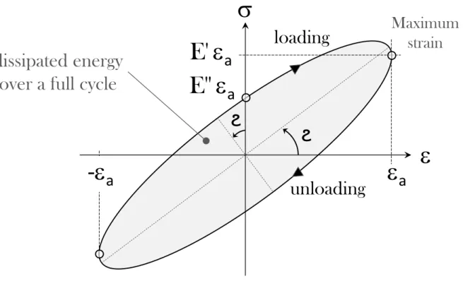
2.2 HYSTERESIS LOSSES . . . 46
2.3 HYSTERESIS POWER LOSSES OF BELTS . . . 47
2.3.1 Bending losses . . . 50
2.3.2 Stretching losses . . . 52
2.3.3 Flank compression losses . . . 54
2.3.4 Radial compression losses . . . 55
2.3.5 Shear losses . . . 58
2.3.6 Total belt hysteresis losses . . . 63
2.3.7 Results . . . 63
2.3.8 Conclusions about belt-hysteresis losses . . . 72
2.4 TENSIONER-HYSTERESIS LOSSES . . . 73
2.5 BEARING POWER LOSSES . . . 74
2.5.1 Model . . . 74
2.5.2 Bearing radial loads . . . 75
2.7 BELT VIBRATION LOSSES . . . 80
2.8 NUMERICAL AND EXPERIMENTAL RESULTS . . . 83
2.9 SUMMARY AND CONCLUSIONS . . . 86
3 FEAD POWER LOSSES OPTIMIZATION 87 3.1 METHODS . . . 88
3.2 OPTIMIZATION INPUT PARAMETERS . . . 90
3.3 GENETIC ALGORITHM . . . 91 3.3.1 Fitness function . . . 91 3.3.2 Implementation . . . 92 3.3.3 Genetic functions . . . 94 3.4 DYNAMIC PROGRAMMING . . . 95 3.4.1 Principle . . . 95 3.4.2 FEAD application . . . 96
3.5 NUMERICAL AND EXPERIMENTAL RESULTS . . . 98
3.5.1 Simulations . . . 100
3.5.2 Experiments . . . 105
3.6 SUMMARY AND CONCLUSIONS . . . 106
4 EXPERIMENTAL VERIFICATION 107 4.1 TEST FIXTURE . . . 108
4.2 DEVELOPMENT TESTS . . . 110
4.2.1 2 pulleys system . . . 110
4.2.2 3 pulleys and 1 idler-pulley . . . 112
4.3 INDUSTRIAL CASE STUDIES . . . 113
4.3.1 EURO-6 . . . 113
4.3.2 EDIT . . . 115
4.3.3 SUMMARY AND CONCLUSIONS . . . 117
5 SIMULATION TOOL 119 5.1 PLFead . . . 120 5.2 STRUCTURE . . . 121 5.2.1 Modules . . . 121 5.2.2 Flowcharts . . . 122 5.3 INTERFACES . . . 123 5.3.1 Geometry . . . 123 5.3.2 Material . . . 125 5.3.3 Dynamics . . . 126 5.3.4 Power losses . . . 127 5.3.5 Optimization . . . 128
5.4 SUMMARY AND CONCLUSIONS . . . 129
6 EXPERIMENTAL CHARACTERIZATION AND SIDE RESEARCH 131 6.1 BELT STIFFNESS AND DAMPING . . . 132
6.2 PULLEY-BELT FRICTION COEFFICIENT . . . 135
6.2.1 1st method: global friction coefficient . . . 135
6.2.2 2nd method: local friction coefficient . . . 136
6.3 TENSIONER CHARACTERIZATION . . . 140
6.3.1 Experimental setup . . . 140
6.3.2 Tensioners dissipative behavior . . . 141
6.3.3 Conclusions about tensioners characterization . . . 143
6.4.1 General characterization . . . 144
6.4.2 Implementation of elastomeric constitutive law . . . 145
6.4.3 Classic model . . . 146
6.4.4 TVD rubber-ring viscoelastic properties . . . 147
6.4.5 Viscoelastic model . . . 148
6.4.6 Results . . . 149
6.4.7 Dynamic Mechanical Analysis . . . 149
6.4.8 Numerical results . . . 150
6.4.9 Experimental verification . . . 153
6.5 SUMMARY AND CONCLUSIONS . . . 155
7 SUMMARY, CONCLUSIONS, AND FUTURE WORK 157 7.1 SUMMARY AND CONCLUSIONS . . . 158
7.2 FUTURE WORK . . . 160 8 FRENCH SUMMARY (Résumé étendu) 161 Chapitre 1. Introduction . . . 162 Chapitre 2. Modélisation . . . 164 Chapitre 3. Optimisation . . . 169
Chapitre 4. Vérification expérimentale . . . 172
Chapitre 5. Outil de simulation . . . 176
Chapitre 6. Caractérisations et recherche additionnelle . . . 180
Chapitre 7. Conclusions et futurs travaux . . . 186
APPENDICES 193 A1: Hysteresis loop area analysis . . . 193
A2: Belt/pulley contact pressure . . . 195
A3: Poly-V belt Finite Element Analysis . . . 197
A4: Belt elastomer characterization . . . 200
A5: Belt-hysteresis enhanced analysis . . . 202
A6: GABO EPLEXOR R, DMA machine . . . 204
A7: Development of the sliding velocity . . . 205
A8: FEAD optimization via Genetic Algorithm . . . 206
A9: FEAD optimization using Dynamic Programming . . . 207
A10: EDIT tensioner hysteresis curves . . . 208
𝐵 Belt width 𝑖, 𝑝 𝑖𝑡ℎ, 𝑝𝑡ℎpulley of the poly-V belt transmission
𝐵𝑑 Width of one V (belt-rib) 𝜙𝑝 Individual wrap angles, with 𝑝 = 1, 2, … , 𝑛𝑝
𝑛 Number of ribs composing the poly-V belt 𝜔𝑝 Individual pulley angular speed, with 𝑝 = 1, 2, … , 𝑛𝑝
𝑑𝑏 Poly-V belt setting diameter □𝑅 Refers to the driver pulley (s), e.g. 𝜙𝑅, 𝜔𝑅, etc.
𝐻 Thickness of the poly-V belt □𝑁 Refers to the driven pulley (s), e.g. 𝜙𝑁, 𝜔𝑁, etc.
𝐻𝑡 Thickness of the top (backside) layer 𝑉𝑏 Belt linear velocity ( 𝑉𝑏= 𝑉 = 𝜔 𝑅 )
𝐻𝑏 Thickness of the middle layer 𝜌𝑏 Belt mass per unit length
𝐻𝑐 Thickness of the ribs layer 𝐶𝑝 Torque imposed to a generic pulley 𝑝
𝜙 Belt-pulley wrap angle 𝑅𝑝 Pulley pitch radius, 𝑅𝑝= 𝑟𝑝with 𝑝 = 1, 2, … , 𝑛𝑝
𝜙𝑎 Belt-pulley adhesion angle 𝑑𝑝 Pulleys’ diameters, 𝑑𝑝= 2 𝑟𝑝with 𝑝 = 1, 2, … , 𝑛𝑝
𝜙𝑠 Belt-pulley sliding angle □𝑠 Refers to the slack belt-span (s) or sliding angle (s)
𝑇 Belt span tension □𝑡 Refers to the tight belt-span (s)
𝑇𝑡 Belt span tight tension □𝑎 Refers to the adhesion angle (s)
𝑇𝑠 Belt span slack tension 𝜀𝑎𝑏𝑒𝑛𝑑𝑚𝑎𝑥 Maximum strain amplitude due to bending
𝑇𝑐 Centrifugal action 𝑊ℎ𝑏𝑒𝑛𝑑 Energy lost by bending-hysteresis
𝑇𝑜 Belt setting (initial, static) tension 𝐸𝐻𝑡ʺ Appropriate top layer 𝐸ʺ(plain strain conditions)
𝑇0𝑚𝑖𝑛 Minimum belt setting tension 𝐸𝐻𝑏ʺ Appropriate middle layer 𝐸ʺ(plain strain conditions)
𝜇 Belt-pulley friction coefficient 𝐸𝐻𝑐ʺ Loss modulus of the ribs layer material
𝜇𝑔 Belt-pulley global friction coefficient 𝑊ℎ𝑠𝑡 Energy lost by stretching-hysteresis
𝜇𝑙 Belt-pulley local friction coefficient 𝐸𝐵𝑒𝑙𝑡ʺ Longitudinal loss modulus of the full belt
𝛼 Wedge angle of the ribs/pulley contact surface 𝜀𝑎𝑠𝑡 Strain amplitude due to belt stretching
𝑃𝐿𝐹𝐸𝐴𝐷 FEAD total power loss 𝐴 Belt cross-sectional area
𝑃𝐿ℎ𝑦𝑠 Total Hysteresis power loss 𝑐 (𝐸𝐴) Tensile modulus or strain stiffness along the belt
𝑃𝐿𝑏𝑒𝑎𝑟 Total bearings power loss 𝑘 𝑘𝑡ℎbelt member: top, middle, cord or ribs
𝑃𝐿𝑠𝑙𝑖𝑝 Total belt-pulleys power loss 𝐸𝐻𝑡ʹ Appropriate top layer 𝐸ʹ(plain strain conditions)
𝑃𝐿𝑣𝑖𝑏 Total belt-vibration power loss 𝐸𝑐𝑜𝑟𝑑ʹ Storage modulus of the belt tension cords
𝑃𝐿𝑏𝑒𝑙𝑡−ℎ𝑦𝑠 Total belt-hysteresis power loss 𝐸𝐻𝑏ʹ Appropriate middle layer 𝐸ʹ(plain strain conditions) 𝑃𝐿𝑡𝑒𝑛𝑠−ℎ𝑦𝑠 Total tensioner-hysteresis power loss 𝐸𝐻𝑐ʹ Storage modulus of the ribs layer material
𝑊ℎ Energy loss by hysteresis 𝐴𝐻𝑡 Cross-sectional area of the belt top-layer
𝐸∗ Complex modulus of the poly-V belt/TVD 𝐴
𝑐𝑜𝑟𝑑 Cross-sectional area of the tension-cords layer
𝐸′ Storage modulus of the poly-V belt/TVD 𝐴
𝐻𝑏 Cross-sectional area of the belt middle-layer
𝐸′′ Loss modulus of the poly-V belt/TVD 𝐴
𝐻𝑐 Cross-sectional area of the belt ribs-layer
ϩ Loss factor of the viscoelastic material 𝜈 Poisson ratio of the belt elastomer (rubber)
𝜀 [𝜀𝑎] Dynamic strain [dynamic strain amplitude] 𝑃𝑐 Pulley-belt contact pressure
𝜎 [𝜎𝑎] Dynamic stress [dynamic stress amplitude] 𝑊ℎ𝑓𝑐 Energy lost by flank-compression-hysteresis
𝑗 Imaginary unit or 𝑗𝑡ℎbelt-span of the FEAD 𝜀
𝑎𝑓𝑐 Strain amplitude due to belt flank compression
𝜃𝑒𝑥𝑝 Temperature experienced by the belt/TVD 𝐴1𝑉 Cross-sectional area of one V (belt-rib)
𝑓𝑒𝑥𝑝 Frequency experienced by the belt/TVD 𝑃𝑧 Horizontal component of 𝑃𝑐
𝜀𝑒𝑥𝑝 Strain amplitude experienced by the belt/TVD 𝑃𝑣 Vertical component of 𝑃𝑐
𝜀𝑎𝑏𝑒𝑛𝑑 Strain amplitude due to belt bending 𝑑𝑆 Infinitesimal element of the belt contact surface
𝑥 Through-thickness distance from neutral axis 𝑊ℎ𝑟𝑐 Energy lost by radial-compression-hysteresis
𝑅 Radius of the curved belt, usually, 𝑅 = 𝑅𝑝 𝜀𝑎𝑟𝑐 Strain amplitude due to belt radial compression
𝑥𝑒𝑞 Arbitrary 𝑥 in the rib layer □𝐻 Refers to the properties belonging to the layer "H"
𝐵𝑒𝑞 Equivalent 𝐵 in the rib layer □𝐻𝑡 Refers to the poly-V belt top layer properties
𝐻𝑠ℎ Thickness of the sheared layer 𝐿3 Distance from the front-bearing to the pulley
𝐻𝑐∗ Hypothetical thickness of the sheared-layer in 𝐻𝑐 𝐷 Seating-Unseating distance vector
𝑊ℎ𝑠ℎ Energy lost by shear-hysteresis 𝑠 , 𝑢 Seating-Unseating points
𝐺∗ Complex modulus of belt or TVD material (shear) 𝑊
𝑖 Weight vector of the pulley "i"
𝐺′ Storage modulus of belt or TVD material (shear) 𝐺 Unit vector representing the gravity
𝐺′′ Loss modulus of the belt or TVD material (shear) 𝜇𝑇
𝑖 Unit vector in the belt-span Tidirection
𝛾𝑎𝑠ℎ Shear angle along the adhesion arc (𝑅 𝜙𝑎) 𝑇𝑖 𝑖𝑡ℎbelt-span vector
𝐴𝑠ℎ Cross-sectional area of the sheared layer 𝑇𝑖 Belt-span tension, Ti = Ti= norm Ti
𝜏𝑠ℎ Shear stress proportional to 𝛾𝑎𝑠ℎ 𝐹𝑟 Belt/pulley resultant radial force
𝜛 Deflection due to cyclic shear loading 𝐹𝑟_𝑘 𝑘𝑡ℎFrof a FEAD containing𝑘 shafts
𝛥𝑉𝑇 Belt-pulley speed difference for driver pulleys 𝐹𝑟_𝑘_𝑓 Component of Fr_kacting on the front bearing
𝛥𝑉𝑆 Belt-pulley speed difference for driven pulleys 𝐹𝑟_𝑘_𝑟 Component of Fr_kacting on the rear bearing
𝑦 Sum of increments along the arc of contact 𝑃 , 𝐶 , 𝜔 Power, Torque, angular velocity
𝜀𝑠 Strain at the belt-pulley seating point 𝑓𝑃, 𝑓𝐶, 𝑓𝜔 Power, Torque, Speed loss factors
𝐺∗ Dimensionless quantity used in shear losses 𝑠𝑖 Slip (s = 𝑓𝜔) quantity on a generic pulley i
𝐿 Belt theoretical length (≈ size of the FEAD path) 𝜀 Strain in the belt longitudinal direction
𝐸𝑐𝑜𝑟𝑑∗ Complex modulus of the belt tension cords 𝑉𝑡, 𝑉𝑠 Belt linear velocity at tight and slack free spans
𝐸𝑐𝑜𝑟𝑑ʺ Loss modulus of the belt tension cords 𝑟𝑐𝑝 radius after belt radial compression
𝐸𝐵𝑒𝑙𝑡∗ Longitudinal complex modulus of the poly-V belt 𝑥𝑐𝑝 Belt radial compression
𝐸𝐵𝑒𝑙𝑡′ Longitudinal storage modulus of the poly-V belt 𝐾ℎ Arbitrary radial stiffness of a generic layer h 𝐸𝐵𝑒𝑙𝑡′′ Longitudinal loss modulus of the poly-V belt 𝑉𝑏, 𝑉𝑝 Belt and pulley linear velocities
𝛷𝐻𝑡 Volume fraction of the top layer material 𝑉𝑠𝑙 Sliding velocity between the belt and the pulley
𝛷𝑐𝑜𝑟𝑑 Volume fraction of the cords layer material 𝐶∗ Dimensionless quantity used in slip losses
𝛷𝐻𝑏𝐻𝑐 Volume fraction of middle + ribs layers materials 𝜔𝐶𝑆 Crankshaft angular speed
𝛷𝐵𝑒𝑙𝑡 Volume fraction of the poly-V belt, equal to 1 𝑃𝑖 Power transmitted by the pulley i
𝑇𝑟𝑒𝑓 Temperature of reference for the master curves 𝑊𝑠𝑝𝑎𝑛𝑗 Belt-hysteresis energy loss in the span j
𝑎𝑇 Master curves, data shifting, constant coefficients 𝑃𝐿𝑠𝑝𝑎𝑛𝑗 Belt-hysteresis power loss in the span j
𝜃𝑡 Tensioner rotation angle 𝛥𝜀𝑗 Variation of strain in the span j
𝜃𝑡_0 Initial tensioner rotation angle 𝛥𝑇𝑗 Variation of tension in the span j
𝜃𝑡_𝑒𝑞 Tensioner rotation angle at equilibrium 𝜆 Number of complete hysteresis loops
𝛥𝜃𝑡 Variation of the tensioner arm angle 𝑥𝑐 Pulley center‘s x-coordinate of the test bench
𝐶𝑓𝑐 Tensioner frictional torque 𝑦𝑐 Pulley center‘s y-coordinate of the test bench
𝑘𝑡 Tensioner arm stiffness 𝐹𝑓 Fitness function (function to be minimized)
𝑊𝑡𝑒𝑛𝑠−ℎ𝑦𝑠Tensioner-energy loss for 1 cycle 𝑥𝑖 Pulley center‘s x-coordinate of the pulley i
𝛺𝑡 Tensioner oscillation frequency 𝑋 Vector containing all 𝑥𝑖, i.e. 𝑋 = 𝑥1, 𝑥2, … , 𝑥𝑛𝑝 ʹ
𝑃𝐿𝑏 Bearing power loss 𝑦𝑖 Pulley center‘s y-coordinate of the pulley i
𝑀𝑏 Bearing total frictional moment 𝑌 Vector containing all𝑦𝑖, i.e. 𝑌 = 𝑦1, 𝑦2, … , 𝑦𝑛𝑝 ʹ
𝑛𝑏 Bearing rotational speed 𝛴𝜌 Power loss model constant values
𝑀𝑟𝑟 Rolling frictional moment 𝑋𝑜𝑝𝑡 Optimized center X-coordinates
𝑀𝑠𝑙 Sliding frictional moment 𝑌𝑜𝑝𝑡 Optimized center Y-coordinates
𝑀𝑠𝑒𝑎𝑙 Frictional moment of bearing seals 𝑇0𝑜𝑝𝑡 Optimized belt-setting tension
𝑀𝑑𝑟𝑎𝑔 Frictional moment due to drag 𝑂1 Center of the pulley 1 (crankshaft)
𝑛𝑠 Number of shafts 𝑂𝑖 Center of a generic pulley i
𝑃𝐿𝑏_𝑖 Total power loss of the ithbearing 𝑇0𝑚𝑖𝑛∗ Minimum belt setting tension to transmit power
𝑃𝐿𝑏_𝑖_𝐹 Power loss of the ithfront bearing 𝑇0
𝑚𝑎𝑥 Maximum belt setting tension
G1 Part of the t that is selected to t+1 EDIT Efficient DIstribution Truck
G2 Part of the t that is recombined, then be part of t+1 FUI Single Inter-Ministry Fund
G3 Part of the t that is mutated, then be part of t+1 EURO-6 European emission standard No 459/2012
𝑍 Individual criterion of a DP optimization problem FEAD Front Engine Accessory Drive
𝑆 State of each DP sub-problem DMA Dynamic Mechanical Analysis
𝑈 Decision variables acting on each DP sub-problem PLFead Power Losses Fead, simulation tool
𝑥𝑚𝑖𝑛 Minimum 𝑥𝑖reached by GA or DP optimization MATLAB MATrix LABoratory, software
𝑥𝑚𝑎𝑥 Minimum 𝑥𝑖reached by GA or DP optimization TVD Torsional Vibration Damper
𝑦𝑚𝑖𝑛 Minimum 𝑦𝑖reached by GA or DP optimization PK, PJ, … Types of poly-V belt profile
𝑦𝑚𝑎𝑥 Maximum 𝑦𝑖reached by GA or DP optimization PET Poly Ethylene Terephthalate
v , 𝑤 DP intermediate standard sub-problem examples EPDM Ethylene Propylene Diene Monomer
𝑠𝑖 Generic step from 2 to 𝑠𝑛 when optimizing by DP MT, HT Mechanical, Hydraulic Tensioners
𝑠𝑛 Number of steps when optimizing using DP DR, DN DriveR, DriveN pulleys
𝑉𝑠𝑖 DP state of the step𝑠𝑖, composed of 𝑋 , 𝑌 , 𝑇0, 𝛴𝜌 PL Power Loss or Power Losses
𝐹 DP function to be optimized (≈ 𝐹𝑓of GA) BC Boundary Conditions
𝑥𝑑 Displacement of the system used to identify EA GABO Dynamic Mechanical Analysis machine
𝑚𝑑 Mass of the 1DOF system used to identify EA PLMap(s) Power Loss Map (s)
𝑘𝑑 Stiffness of the 1DOF system used to identify EA SKF Bearing manufacturing company
𝑐𝑑 Damping of the 1DOF system used to identify EA CS CrankShaft
𝑙𝑑 Generic belt-span length used to identify EA AD Accessory Drive
𝐹𝑒𝑥𝑡 External force applied to the 1DOF system PLS Power Loss Simulated
𝑋𝑑 Absolute value of the displacement 𝑥𝑑 PLM Power Loss Measured
𝑐𝑐 Critical damping of a mass-spring-damper model BF Brute Force method
𝑓𝑛 Natural frequency of the belt testing system/TVD DP Dynamic programming method
𝜔𝑛 Radian frequency of the belt testing system/TVD GA(s) Genetic Algorithm(s)
𝜔0 Radian frequency of the undamped system Multi-DP Multi Decision Process
𝛼𝑑 Damping factor of a given vibration signal RAM Random Access Memory
𝑛𝑣𝑖𝑏 Number of periods (𝑛) of a vibration signal CPU Central Processing Unit
𝛿𝑑 Logarithmic decrement of a vibration signal PS Power Supplied
𝑃𝑥 Normal load applied to poly-V belt sample PC Power Consumed
𝑇𝑚𝑎𝑥 Traction force applied to poly-V belt sample WP Water Pump
𝐾𝑐𝑠𝑡 Constant stiffness of the TVD rubber-ring ALT ALTernator
𝑅𝑟𝑟 External radius of the TVD rubber-ring AC Air Conditioner
𝐿𝑟𝑟 Width of the TVD rubber -ring PG Power Generated
𝑒𝑟𝑟 Thickness of the TVD rubber -ring GUI Graphical User Interface
𝐼𝑛 Inertia of the TVD corresponding to 𝑓𝑛 Ra Roughness average
𝜉 Damping ratio of the TVD rubber-ring DOF Degree of Freedom
𝜔𝑎𝑐𝑦 Radian frequency of the engine torque fluctuation FRF Frequency Response Function
𝜃𝐶𝑆 Harmonic excitation motion from the engine (CS) FEA Finite Element Analysis
𝜃𝑎𝑚𝑝 Amplitude of the harmonic excitation motion F(x) Function of “ x ”
𝜃1 Angular lag and the TVD angular DOF MS Measuring System
𝐶𝑐𝑠𝑡 Constant damping of the TVD rubber-ring 𝐼1 Inertia of the TVD outer-ring
𝐾𝑣𝑎𝑟 Varying stiffness of the TVD rubber-ring
𝐶𝑣𝑎𝑟 Varying damping of the TVD rubber-ring
Chapter 1
INTRODUCTION
Contents
1.1 MOTIVATION . . . . 22 1.2 LITERATURE REVIEW . . . . 25 1.3 POLY-V BELT TRANSMISSION . . . . 26 1.4 FRONT ENGINE ACCESSORY DRIVE . . . . 27 1.5 POLY-V BELT . . . . 28
1.5.1 Material . . . 28 1.5.2 Design . . . 29
1.6 ACCESSORIES . . . . 30
1.6.1 Poly-V pulley . . . 31 1.6.2 Torsional Vibration Damper pulley . . . 32
1.7 TENSIONERS . . . . 33
1.7.1 Idler-pulley . . . 33 1.7.2 Mechanical tensioner . . . 34 1.7.3 Hydraulic tensioner . . . 35
1.8 KEY ENTRY TOPICS . . . . 36
1.8.1 Geometry . . . 36 1.8.2 Belt span tensions . . . 37 1.8.3 Belt setting tension . . . 38 1.8.4 Sliding and adhesion arcs . . . 39
1.9 OBJECTIVES . . . . 41 1.10 TASK OUTLINE . . . . 42 1.11 CONTRIBUTIONS . . . . 43
1.1
MOTIVATION
Over the last years, significant research effort has been directed towards developing vehicle transmissions more energy efficient. This effort has been a direct consequence of the new environmental regulations encouraging truck and car manufacturers to reduce the power losses of their engines. Recently, for example, the European Union have set penalties for car manufacturers of 95 euros per gram of CO2/km for each new vehicle sold from
2019 exceeding this emission limit. Hence, modeling and optimizing the power losses in the transmissions of vehicles is extremely important to attain emission reduction goals. Moreover, for development purposes and in design of power transmissions, it is worth predicting the potential power losses before manufacturing. Thus, to predict the power losses in poly-v belt transmissions, theoretical models have been developed taking into consideration different types of power loss in a Front Engine Accessory Drive (FEAD). These losses have several origins: from the poly-V belt or from the mechanical compo-nents of the system (bearings, tensioners). In the first case, energy is dissipated inside the belt due to the hysteretic behavior of the belt constitutive elastomer (internal losses or torque losses). However, energy is also dissipated inside bearings and at the surface of the belt due to belt-pulleys slip (external losses or speed losses). Next, optimizing the power losses coming from the FEAD of vehicles helps reducing the engine fuel consumption and the emission of greenhouse gases. Thus, an optimization method based on a genetic algorithm has also been applied, i.e. principles of real life (natural selection, cross-over and mutation) applied to computations have been used to minimize power losses, since genetic algorithms are commonly used in optimization because of their adaptability to handle complex engineering problems (FEADs). For comparison purposes, the dynamic programming which is a technique based on the principle of sub-problematization has also been implemented. The optimization-problem consists in minimizing the power loss function representing the power losses taking place in a front engine accessory belt drive or the emissions of polluting gases. Results have shown in this thesis that the total power losses can be reduced by tens of percent by adjusting both the positions of the engine accessories (geometric parameters) and the belt setting tension (operating parameters). Experimental results confirm these numerical predictions from theoretical power loss mod-els implemented in a simulation tool with exceptional characteristics. Thus, this thesis is motivated by the environmental questions about saving energy, the vehicle manufacturers’ interrogations about how to improve their engines and my determination to carry forward the science and technology.
EDIT project
This thesis has been achieved within the frame of the EDIT (Efficient Distribution Truck) collaborative industry project. Indeed, Renault Trucks has been leading a collaborative industry project aiming to reduce the fuel consumption of distribution trucks compared with the current production vehicle EURO-6. Six industry partners have been working on the EDIT project alongside Renault Trucks, they are: Valeo, Lamberet, Michelin, BeNomad, INSA Lyon (LaMCoS) and IFSTTAR (LICIT).
Using a Renault Range D Wide truck with refrigerated body as a prototype (Fig. 1.1), the project aimed to design and develop a demonstration refrigerated vehicle consuming 13% less fuel than the reference Euro-6 distribution truck.
Figure 1.1 – Renault Range D Wide truck (Urban Lab 2).
Urban Lab 2 uses technologies, to which each partner have been contributing with their expertise, focusing on the key areas: aerodynamics, tyres, connectivity and hybridization/ optimization of the engine. Indeed, according to Renault Trucks Press Releases:
Aerodynamics
To reduce the aerodynamic drag of the Urban Lab 2 - and therefore its fuel consump-tion - engineers worked on airflow throughout the vehicle. Lamberet and Renault Trucks adapted the cab, chassis and refrigerated body to the recommendations of aerodynamic specialists, whilst meeting the regulatory and operating requirements of controlled temper-ature transport. The first step involves reducing the front surface area: "The refrigeration unit is normally located above the cab", explained François Savoye, Energy Efficiency Strategy Manager at Renault Trucks. "On Urban Lab 2, we decided to position it in the wheelbase of the vehicle to free up space overhead and optimize the body/tractor link to lower the body and improve airflow. This meant we could incorporate a roof deflector shaped to provide seamless continuity with the body. Redesigning the interior architec-ture of the refrigerated body has made a marked improvement in the shape of the roof, without adding to the height. As for the sides of the vehicle, these are fitted with textile side deflectors. "We have used a PVC-coated textile for the first time", François Savoye added. "When stretched and fitted on the side protectors, it provides a light, effective and economic system."
Lateral airflow is also boosted by streamlined wheels and the fitting of rear deflectors that are perfectly in keeping with the architecture and continuity of the tailgate. These deflectors are angled so as to reduce depression in the slipstream of the vehicle and do not require any manual operation when handling the doors. The access step is completely covered thanks to a mobile guard opened by door extensions that provides a seamless con-tinuity between the upper and lower sections of the cab. Ground clearance is optimized by the addition of flexible components, thus optimizing air flow in the under-structure. Lastly, replacing wing mirrors with a system of profiled cameras and internal feedback screens also helps reduce vehicle air resistance.
Tyres
Michelin has been working with Renault Trucks to develop energy-saving tyres specially designed for distribution vehicles. "The objective of these tyres is to further reduce rolling resistance, without negatively impacting other performance criteria, such as safety, grip or longevity", explained Jean-François Cordonnier, Truck Pre-development Manager at Michelin. To this end, Michelin has deployed its wide range of technologies, in particular Infini-Coil technology, to guarantee tyre endurance and safety. Firstly, the self-generating tread ensures a lasting grip throughout the life of the tyre and secondly, silica is used as a reinforcing agent in the tread to improve the compromise between longevity and rolling resistance.
Connectivity
For Renault Trucks, drivers play a key role in reducing fuel consumption. This is why Urban Lab 2 features technology to help them with their driving by connecting the vehicle to infrastructures. Working with the company BeNomad, engineers have developed special navigation software that provides this connectivity. For each journey, the GPS proposes the route that is the most efficient and uses the least fuel, estimating both the predicted journey time and fuel consumption. This software has been configured to take not only fuel consumption into account, but also, and above all, the operational constraints of a distribution vehicle. Lastly, Urban Lab 2 is connected to infrastructures to optimize driving through green lights. When Urban Lab 2 approaches traffic lights, it receives information from the lights and the system calculates if it is more efficient to brake or accelerate, when conditions and regulations allow it to do so. This therefore limits the amount of stop-start driving, which has a highly negative impact on fuel consumption. Also, the traffic modeling expertise of LICIT has helped Renault Trucks to effectively integrate the effect of traffic on fuel consumption.
Hybridization
To reduce fuel consumption, Urban Lab 2 also proves innovative in its engine design, with a system combining Stop&Start and micro-hybrid technology, developed in partnership with Valeo. The Stop&Start system switches off the engine when the vehicle comes to a halt, at a red light for example, thereby reducing fuel consumption. In addition, the micro-hybrid system recovers "free" energy, such as energy generated during foot lift or braking, via a high-power (48 V) reversible electric machine. This energy can be used to drive the electrical accessories of the vehicle or reduce the mechanical power required by the thermal engine.
Renault Trucks has also been working with LaMCoS to reduce power loss in the front face of the engine in order to optimize the overall efficiency of the micro-hybrid system.
Finally, Renault Trucks and its partners have set themselves an ambitious target and have recently achieved the reducing fuel consumption of 12.8% compared to an equivalent Renault Trucks D Wide Euro-6. This amount was confirmed by measurements in practice.
Renault Trucks has even won the "Low Emissions Drivetrain Award" for its laboratory distribution vehicle (Urban Lab 2). This prize, awarded by the LUTB Transport and Mobility Systems cluster and the PFA Automotive Industry and Mobilities, as part of the Solutrans Innovation Awards, was presented to the manufacturer at the Lyon Chamber of Commerce and Industry on 21 November 2017.
1.2
LITERATURE REVIEW
Serpentine belts: Several recent studies have mainly focused on serpentine belt drive
systems (see Fig. 1.2). Hawker [1] considered the belt longitudinal deflection and pulleys rotational vibrations in the analysis of free and forced response. Hwang et al [2] proposed a model to examine rotational vibration of a serpentine belt drive and the prediction of belt slip. Kraver et al [3] used a similar model to examine tensioner pivot dry friction using an equivalent viscous damper. Beikmann et al [4] demonstrated that the operating equilibrium is determined by an iteration of the nonlinear, time-invariant equations of motion. Beikmann et al also considered transverse and torsional belt vibrations [5] [6]. Parker [7] presented an efficient method to calculate the natural frequencies, vibration modes, and dynamic response of serpentine belt drive systems and to analytically formu-late the eigensensitivities to system parameters. Chowdhury et al [8], in addition to the modeling of the dynamics of the belt, added the shaft on which the pulleys are mounted, they attempted to analytically determine the effect of the vibration of the flexible shaft-pulley system on the tension fluctuation of the attached belt span. These studies provide a good basis of relevant contributions and the serpentine belt drive dynamic responses detailed in some of these works are of great importance for the belt-vibrations power loss theory presented in this thesis.
Modelling and optimization of the power losses in poly-V belt transmissions:
Regarding belt transmission systems, most of the works are generally related to their dynamics, e.g., Pan et al [9] have made efforts to model realistically the dynamics and the belt-pulley coupling in belt transmissions, Chowdhury and Yedavalli [8] studied the dynamics of belt-pulley-shaft systems, the slippage at the belt-pulley interfaces is ignored - which is often the case. However, sometimes the power losses (or their effects) have been indirectly studied (considered) through the friction or the slippage between the belt and the pulley, for example, Srivastava [10] and Haque reviewed the state-of-the-art research on dynamic modeling and control of friction-limited continuously variable transmissions and Lubarda [11] considered the mechanics of belt-friction (power loss) before the state of gross slip and determined the belt force before the pulley-belt slipping, etc. Most of the works directly related to power losses in belts transmission were mainly initiated by Amijima [12], [13], Gerbert [14], Childs and Cowburn [15]. However, only flat and V belts were considered. Furthermore, constant elastomeric properties of the belt rubber (stor-age and loss moduli) were used even though polymeric materials are known for exhibiting complex time and temperature dependent hysteretic properties [16]. Several authors such as Chen et al. [17], Almeida et al. [18] studied the global efficiency of belt transmission and therefore the global power loss. In the case of poly-V belts, experimental studies were carried out on the analysis of the pulley-belt slip (Manin et al. [19]) and on the iden-tification of the friction coefficient between the belt and the pulley (Cepon et al. [20]). Recently, the speed and torque losses in poly-V belt drives with two equal-sized pulleys have been studied by Balta et al. in [21] and [22], respectively. Regarding the power losses in poly-V belts, a first model related to the hysteresis dissipation of the poly-V belt submitted to dynamic loading, was originally developed by Manin et al. [23]. Moreover, with respect to the optimization of power losses in poly-V belt transmissions, there is not much literature on this topic, except the studies of (1) Zhu et al [24] which have obtained the dynamic response of a FEAD and optimized the belt vibrations; and (2) Balta et al. [21] which proposed a design optimization procedure emerged from their experiments. Finally, most of the works related to the account for the rubber viscoelastic behavior in the structural components (belt, pulley, dampers) of the FEAD are about the impact of the poly-V belt viscoelasticity on its different vibration modes [25] [26] [27] [28] [29].
1.3
POLY-V BELT TRANSMISSION
Belts are commonly used in power transmission systems. In many of these systems there is a flexible element (belt) subjected to initial tension and moving in its axial direction. Indeed, there are essentially three types of belts, flat, trapezoidal and poly-V (V-ribbed) belts. They are used in mechanical systems such as textile and spinning machines, con-veyors, industry fans, etc [14]. In this work, we are focusing on poly-V belts which are nowadays widely used in the automotive and truck industries as an essential part of the power transmission of vehicles (Fig. 1.2).
Figure 1.2 – Typical poly-V belt accessory drive system.
Poly-V belts are generally fabricated with composite materials that combine synthetic rubber backing (flexibility), polyester cords (longitudinal rigidity) and some fibrous poly-chloroprene base compounds which interacts directly with the pulley surface (Fig. 1.3).
Synthetic rubber backing Polyester tension member
Fibrous polychloroprene base compound
(high friction surface) 6 PK 1980
6 Number of ribs
PK Profile designation / spacing the ribs 3.56 mm 1980 Effective length [mm]
1.4
FRONT ENGINE ACCESSORY DRIVE
In most cases, on the front engine of vehicles, power is delivered with a single poly-V (v-ribbed) belt from the crankshaft to the individual accessories such as the compressor, the alternator, the water and steering pump, etc. The belt transmission system including all the individual accessories is commonly named Front Engine Accessory Drive (FEAD). A Renault-Trucks FEAD (hereafter considered in the analyses) is presented in Fig. 1.4. In addition, an automatic tensioning device whose function is to adjust the belt slack span tension value over a wide range of operating conditions is also used (Fig. 1.4, left).
Poly-V belt shape
Close-up view & cross section
Tensioner Water pump Crankshaft Alternator Air conditioner Δθ
Figure 1.4 – EURO-6 Renault-Trucks FEAD with focus on the Poly-V Belt (inset).
Based on various areas of research, e.g. the hybridization of engines, new prototypes of FEADs have emerged. In Fig. 1.5 the FEAD of the Urban Lab 2 laboratory vehicle is presented. As previously mentioned, this is one of the technical solutions used to reduce fuel consumption. This prototype of FEAD is hereafter also considered in the analyses.
1.5
POLY-V BELT
The poly-V belt considered throughout this work has a PK profile chosen among four different types: PJ, PK, PL and PM which have dimensions as in Fig. 1.6.
… 𝑛 ribs
𝐻
𝐻
𝑏𝐻
𝑡𝑑
𝑏𝐵
𝑑 Dimensions (mm) PJ PK PL PM 𝐻 3.8 5 9/7.5 14.5 𝐻𝑡 1.1 1.5 1.5 2 𝐻𝑏 1.2 1.5 3 4 𝐵𝑑 2.34 3.56 4.7 9.4 𝑑𝑏minimum 20 45 75 180𝐵
Figure 1.6 – Dimensions of the standard profiles of poly-V belts.
In most cases the belt profiles above are selected with the help of charts provided by the belt manufacturers (e.g. Hutchinson, Dayco, etc.) and they are chosen as a function of the power transmitted and the rotation speed of the smallest FEAD’s pulley.
1.5.1
Material
Poly-V belts must be easy to bend to be effective in running on and off the pulleys. They must also be stiff in the longitudinal direction to support the traction force and to prevent excessive sliding against the pulleys [14]. To accomplish these properties, high power capacity poly-V belts are mostly designed with
• A tension member • An elastomer
• A high friction surface
The tension member is a flexible cord layer of high modulus fibers, i.e. PET, polyester as shown in Fig. 1.3, aramid (kevlar) or glass. Sometimes the fibers are directly mixed into an elastomer to get a high modulus matrix.
The tension member is also surrounded by a highly flexible elastomer, i.e. synthetic rubber as in Fig. 1.3, rubber EPDM, polychloroprene or polyurethane. Also fibers are included in the elastomer and oriented so that to increase the load supporting capacity.
The friction surface is the outermost layer directly in contact with the pulley. Either an additional thin layer of some high friction coating (e.g. fibrous polychloroprene base compound as shown in Fig. 1.3) is attached to the belt or the elastomer itself has sufficient friction when it works directly on the pulley.
1.5.2
Design
Poly-V belts are more and more employed and they replace progressively other traditional designs, because of their compactness and their contact surface area up to 2.5 times larger than the contact surface area of flat belts and V-belts (Fig. 1.7).
Poly-V belts are
designed in order to
• Have a larger contact surface area than V belts or flat belts • Improve transmission ratio (1 : 60 vs V belt 1 : 20).
(Does away with the need for stepped pulleys)
• Reduce diameters
(diameters up to 9mm with the H profile compared to 50mm with V belts)
• Reduce belt width
(for a given geometry and the same power transfer)
• Operate in bending and counter bending
(e.g. serpentine belt passing by tensioners in a FEAD)
• Drive several accessories, even from the back of the belt
(serpentine belt layouts)
Figure 1.7 – Benefits of the use of poly-V belts instead of other designs of belts [31].
According to Fig. 1.7, the poly-V belt is not only an improved belt model, but it is also designed to be a combination with the best characteristics of flat belts and V-belts.
From microscopic analyses of the cross-section of the poly-V (Fig. 1.8), a physical model of the poly-V belt is adopted to be used across this work, mainly in the power losses modeling (chapter 2) where the models are based on the assumptions bellow.
Poly-V belt idealized:
Microscopic analysis: Physical Model adopted:
… n ribs Twisted
tension cords
Figure 1.8 – Poly-v belt cross section microscopic analysis and its physical model.
• The poly-V ribs are assumed to be trapezoidal;
• The poly-V tension member is assumed to be composed of several cords, each one with small cords rolled spirally against each other;
• A poly-V belt may be idealized as an assembly of two flat belts and several small V-belts corresponding to the number of ribs.
1.6
ACCESSORIES
In internal combustion engines, accessories are almost exclusively driven by poly-V belts.
Mechanical Tensioners
Hydraulic Tensioners Idler pulley
Overrunning alternator pulley
Water pump pulley
Figure 1.9 – Examples of FEAD components: pulleys and tensioners [32].
According to Schaeffler [32], the primary requirements for accessory drive systems and their automated tensioning systems are listed below:
• Self belt force adjustment during initial installation and maintenance of the FEAD and components including the belt (tolerance compensation of drive components);
• Nearly consistent belt force during operation and the entire life of the transmission (compensation of the belt elongation and wear);
• Reduction of dynamic belt force peaks; • Minimization of slip, noise and belt wear;
• Rating life increase for the entire belt drive system; • Optimal reliability of the overall belt drive system;
• Minimization of friction loss in the overall system, and so forth.
FEAD components can be from simple idler-pulleys equipped with grooved ball/roller bearings to more complex mechanical and hydraulic tensioning systems (Fig. 1.9).
1.6.1
Poly-V pulley
In Fig. 1.10, it is presented several types of pulleys, possibly made of different materials, which may be used to transmit power with a poly-V belt. The manufacturing process of the (poly-V) pulleys which fit the poly-V belt is also shown on the left (Fig. 1.10).
Figure 1.10 – Examples of different types of poly-V pulleys.
The poly-V pulley is a special type of grooved pulley designed to transmit more power than other (e.g. flat or V) models.
Poly-V pulleys have clear advantages over the use of conventional pulleys which are the same as those presented in Fig. 1.7.
According to the intended application, poly-V pulleys can be made of steel, aluminum, brass, etc. They can also be of different diameters, widths and form with splined or bolted shaft couplings. In addition, there exist many possibilities to manufacture them producing various sizes (number of ribs) and profiles as in Fig. 1.10. The width of the poly-v belt is adapted to the power to be transmitted.
1.6.2
Torsional Vibration Damper pulley
Internal combustion engines and especially diesel engines when firing produce torsional crankshaft vibrations. These vibrations are partly due to the cyclic rod forces working on the crankshaft combined with its proper rotation; it results in an irregular rotation speed. These torsional vibrations could lead to excessive belt wear, noise and transverse belt vibrations. That is why it is important to dampen them. For this purpose, a poly-V driving pulley is adapted to be a Torsional Vibration Damper (TVD) for the crankshaft. The principle is to separate into two (or more) mechanical parts the crankshaft pulley and to insert a rubber ring between them, a vibration absorber is therefore obtained (e.g. Fig. 1.11), with the same principle as a TMD (Tuned Mass Damper).
Rubber
Outer and inner metal parts
Figure 1.11 – Single-mass rubber TVD pulley [33].
The most common types of TVD are the single (Fig. 1.11) and dual mass rubber TVD which filters the vibrations from the crankshaft with an additional rubber ring (Fig. 1.12).
Figure 1.12 – Dual-mass rubber TVD pulley [33].
TVDs are mechanical assemblies which dampen the vibrations engendered by the engine torque fluctuations and are generally composed of at least three elements: the hub, a rubber ring and an inertia steel ring with V-ribs on its outer diameter (used as a pulley).
1.7
TENSIONERS
FEAD tensioners can be subdivided into two types. They can be fixed or mobile and belong to two categories, mechanical and hydraulic tensioners. Idler-pulley, mechanical and hydraulic tensioners are briefly presented hereafter.
1.7.1
Idler-pulley
The simplest tensioner, the idler pulley is responsible for guiding and maintaining tension with the drive belt. Examples of this type of tensioner are presented in Fig. 1.13.
Figure 1.13 – Examples of idler-pulleys.
Moreover, there are several interests of introducing an idler pulley: vibration and noise reduction in critical belt spans, prevent collision with the surrounding parts as shown in Fig. 1.14, increase of wrap angles on neighboring pulleys and therefore decrease of setting tension and increasing belt durability.
without idler (collision !!!)
surrounding mechanical
parts
Figure 1.14 – Role of an idler-pulley in a FEAD
The idler-pulleys have similar rating life and noise development requirements as the belt tensioning systems presented in the following sections.
1.7.2
Mechanical tensioner
The Mechanical Tensioner (MT) is an articulated system composed by an idler-pulley attached to a mobile part (arm) connected to the FEAD by a torsion spring (Fig. 1.15).
This type of tensioner is a good cost-optimized solution to automatically maintain poly-V belt drives tensioned. The required belt pre-load force is usually generated by the arm of the lever, the tension pulley as well as the torque exerted by a torsion spring.
A mechanical tensioner can be modeled either by a friction element [34], or by a spring and a damper in parallel. This consists in a friction element (disk, ring and cone) pre-loaded by a torsion spring similar to that in Fig. 1.15.
Tension pulley
Mobile part
Torsion spring
FEAD
Figure 1.15 – Example of MT with its parts (left) and other types (right).
With respect to the damping function of the mechanical tensioner, the principle is simple: as the lever arm moves, a relative motion between two surfaces in contact takes place generating friction, and consequently, damping. The belt pre-load force thanks to the spring torque and damping are adjusted to match the mechanical tensioner application.
Depending on the application and power to be transmitted, the mechanical tensioner can generally be optimized (optimal tensioner-arm length and spring stiffness are employed) in order to reduce belt transverse vibrations and also to increase belt durability.
1.7.3
Hydraulic tensioner
Similar to the mechanical ones, Hydraulic Tensioners (HT) have fixed and mobile parts (Fig. 1.16). They are mainly considered when the system demands a solution with high requirements: significant tensioning force and belt-tensioning/tensioner-size ratio.
Pressure spring
with hydraulic leakage gap inside
Lever arm Tension pulley
Figure 1.16 – Example of HT with its parts (left) and other types (right).
This type of tensioner consists of a hydraulic component with an integrated compression spring and hydraulic leakage gap damping as well as a lever arm with an attached idler pulley (Fig. 1.16, left). The hydraulic leakage gap damping acts in a controlled way and in proportion to the speed generating damping only when needed.
The optimal adjustment of the required belt pre-load force to the relevant application is performed by the HT integrated pressure spring and the converted lever ratio. The required damping is set by adjusting the leakage gap.
The properties of the lubricant (viscosity, compressibility, ...) used inside the hydraulic tensioners ensure the lowest possible damping temperature dependency in combination with excellent resistance to act without hardly wear. This may be one of the biggest advantages of using the hydraulic tensioner. Two design examples (right) of hydraulic tensioner and its constitutive parts (left) are shown in Fig. 1.16.
More details on belt drive systems can be found in [32].
After introducing the power transmission system studied in this thesis, the poly-V belt, the FEAD and its components, let us introduce the minimum necessary to understand the modeling of the power losses developed in chapter 2.
The geometry of the transmission, the belt-span tension, the belt setting tension, the adhesion and the sliding arcs are parameters directly involved in the FEAD power losses. Thus, let us briefly get into a basic theorization of their concepts.
1.8
KEY ENTRY TOPICS
1.8.1
Geometry
To calculate the geometrical parameters of a 2-pulleys belt transmission the formulas in Fig. 1.17 from [30] can be used. They relate the belt theoretical length (L) to the pulley’s diameters (d) and the center distance (e) between the pulleys.
ϕ1 ϕ2
Figure 1.17 – Geometry of a belt transmission composed of two pulleys [30].
If the belt transmission has several pulleys (at least 3 pulleys) as in the case of the Front Engine Accessory Drives (FEADs), the formulas in Fig. 1.18 from [30] and [35] can be used, as is the case in this thesis.
acos acos
acos
1.8.2
Belt span tensions
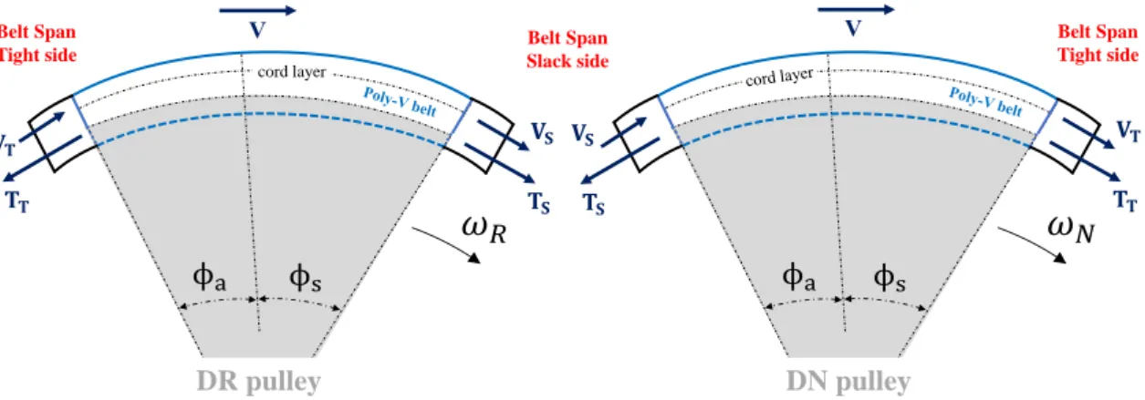
In a FEAD, power is often transmitted from a DriveR (DR) pulley to several DriveN (DN) pulleys by means of friction between the belt and the pulleys. Consequently, the tension varies in the belt. Let us consider the belt transmission system in Fig. 1.19.
𝑻
𝒕
𝜔
𝑁
𝜔
𝑅
𝜙
𝑅𝜙
𝑁DR pulley
DN pulley
𝑻
𝒔
𝑻
𝒕
𝑻
𝒔
Figure 1.19 – Belt transmission system with a DR and a DN pulley.
When it is running, some variation of tension occurs along the angle of contact φ, it means that the belt is pulled on one side and pushed (lack of pulling) on the other side of the DR pulley, giving rise to the tight Tt and slack Ts side tensions. The effective pull (Tt− Ts)
is transmitted between the pulleys via the free spans of the belt.
In the same direction of rotation (i.e. Vb direction), similar to what happens around
the DR pulley, a variation of tension also happens along the DN pulley, but in this case with tensions increasing from Ts to Tt instead of decreasing from Tt to Ts as along the
DR pulley. This is a consequence of the driving and resisting torques imposed by the crankshaft and accessory-drive shafts, respectively.
The phenomenon described above happens similarly in a Front Engine Accessory Drive with the particularity that, in this case, along the FEAD path the effective pull from the crankshaft is partially distributed to all the accessory driven pulleys.
To summarize, the belt-span tension always changes around a pulley transmitting power from a slack to a tight side or vice-versa, the only difference is if the change in the belt tension corresponds theoretically to all (Fig. 1.19) or part (FEADs) of the effective pull generated by the crankshaft. Also, another parameter that changes with changing the belt-span tension is the magnitude of the adhesion φa and sliding φs angles constituting
the wrap angle φ (φa+ φs) of the pulleys [14]. The angle φ of all pulleys in a FEAD can
be determined from the geometry (Fig. 1.18). The adhesion φaand sliding φs angles/arcs
1.8.3
Belt setting tension
The setting tension T0 is the tension existing in all belt-spans when the system is at rest.
This tension must be sufficiently high to guarantee the power transmission on all pulleys when the system is running, i.e. T0 ≥ T0 min as in Fig. 1.20, and therefore, ensuring that
the full pulley/belt slip (gross slip) does not occur.
From the above statement, let us consider the 2-pulleys belt transmission in Fig. 1.19. The calculation of the belt setting tension is also indicated in Fig. 1.19, where T0 is
the belt setting tension and is always calculated considering the smallest pulley in the transmission [30]. Indeed, if the non-slippage is ensured on the smallest pulley, it will also be ensured on the other pulleys of the transmission. Similarly, in a FEAD, it is also necessary to ensure the non-slippage of the belt on all pulleys.
The belt setting tension (𝑇0) depends on : • The torque of the smallest pulley 𝐶1
• The radius of the smallest pulley 𝑟1
• The wrap angle 𝜙1
• The belt-pulley global friction coefficient 𝜇𝑔
• The belt mass per unit length 𝜌𝑏
• The belt linear velocity 𝑉𝑏
𝑇
𝑜≥ 𝑇
𝑜𝑚𝑖𝑛=
2 𝑟𝐶11
𝑒𝜇𝑔 𝜙1 + 1
𝑒𝜇𝑔 𝜙1 − 1
+
𝜌
𝑏𝑉
𝑏2
DR pulley DN pulley DR pulley DN pulley
System stopped System running
𝑇 𝑇0 𝑇 0 𝑇0 𝑇0 𝜙1 𝜙1 𝜙2 𝜙2 𝑪𝟏 𝑪𝟐 𝑇𝑡 𝑇 𝑡 𝑇𝑠 𝑇𝑠
Figure 1.20 – Belt setting tension for a 2-pulleys belt transmission system [30].
In this regard, a minimum belt setting tension T0 ≥ T0 min for each component of the
system can be estimated as in Fig. 1.19 considering the driving and resisting torques from the engine and accessory drives. Thus, the tension is the (highest) setting tension which ensures the power transmission on all accessories of the FEAD.
In practice, the belt manufacturer guide/catalog do not use directly the equation to find
T0 as in Fig. 1.19. The guides for selecting belts consider different correction factor of
the power to be transmitted to take into account the diameter of the smallest pulley, the belt/pulley wrap angles smaller than 180 degrees, the type of the driven machine, the transmission utilization rate per day, the length of the free belt-spans, etc.
1.8.4
Sliding and adhesion arcs
Still considering a 2-pulleys belt transmission system as in Fig. 1.21, when the system is running the belt span tension does not vary continuously over the whole arc of contact (φ) from slack to tight side or vice-versa, but according to Grashof [36] φ is divided into two angles (arcs): the sliding angle φs and the adhesion angle φa. Moreover, according to
Gerbert [14] the tension in the belt varies along the sliding angle φs and remains constant
along the adhesion angle φa. Also, in the sliding arc there is a relative motion in the
longitudinal direction between the poly-V belt and the pulley surface.
DR pulley
DN pulley
𝑻𝒕𝜔
𝑁𝜔
𝑅 𝜙𝑁𝑠 𝑒 𝜇𝑙 𝑠𝑖𝑛𝛼2 𝜙𝑁 behavior 𝑻𝒕 𝑒− 𝜇𝑙 𝑠𝑖𝑛𝛼2 𝜙𝑅 behavior 𝜙𝑁𝑎 𝜙𝑅𝑠 𝜙𝑅𝑎 𝜙𝑁 𝜙𝑅 Tight side Slack side 𝐶𝑅 𝐶𝑁 Constant and equal to 𝑇𝑡 Constant and equal to 𝑇𝑠 𝑻𝒕 𝑻𝒕 𝑻𝒕 𝑻𝒔 𝑻𝒔 𝑻𝒔 𝑻𝒔 𝑻𝒔Figure 1.21 – Variation of tension in the belt along the contact arcs of a simple transmission.
Belt transmissions with 2, 3 or more pulleys have tension distribution profiles similar to that in Fig. 1.21, because the belt tension member is extensible and thin. Thus, there is an extensible belt subjected to varying tension running on stiff pulleys (rigid bodies). This implies that the belt slides on the pulley and the friction is fully developed within the sliding angle φs. In contrast, within the adhesion angle the belt adheres to the pulley.
In this case, no shear occurs since the belt is assumed to be thin, so the tension is constant and no friction exist [14].
In Fig. 1.21, the sliding arc, corresponding to the sliding angle φs, is located towards
the unseating region (where the belt leaves the pulley). Consequently, the adhesion arc, corresponding to the adhesion angle φa, is located towards the seating region [14] (where
the belt meets the pulley), both at the DR and DN pulleys.
Assuming that in poly-V belts no radial sliding occurs (besides circumferential sliding), the magnitude of both DR (φRs) and DN (φN s) sliding angles in Fig. 1.21 are determined from Eqs. 1.1 and 1.2.
Applying the Capstan formula [37] on the DN pulley of Fig. 1.21 gives the varying force
TN(φ) (Eq. 1.1) which results in a varying contact pressure (Appendix A2) and ranges
from Ts to Tt along the sliding arc.
TN(φ) − Tc Ts− Tc = e µl sin( α 2) φN = eµgφN (1.1)
Similarly, applying the Capstan formula on the DR pulley of Fig. 1.21 gives the varying force TR(φ) (Eq. 1.2) which results in a varying contact pressure (Appendix A2) and
ranges from Tt to Ts along the sliding arc.
TR(φ) − Tc Tt− Tc = e− µl sin( α 2) φR = e−µgφR (1.2) Where
• Tc = ρb Vb2 represents the centrifugal action;
• α represents the poly-V belt wedge angle; • µl is the belt-pulley local friction coefficient.
• µg is the belt-pulley global friction coefficient.
Note that along the contact arc between the belt and the DN pulley (Eq. 1.1) the sliding angle φN varies from where it was indicated in Fig. 1.21 to φN s which is a constant value.
Similarly, along the contact arc between the belt and the DR pulley (Eq. 1.2) the sliding angle φR varies from where it was indicated in Fig. 1.21 to φRs (constant value).
As briefly mentioned earlier, from sliding angles φN s and φRs (Eqs. 1.1 and 1.2) the following relations can be used to obtain the adhesion angles φN a and φRa.
φ = φs+ φa (1.3)
Moreover, in Eqs. 1.1 and 1.2 to determine the angles φN sand φRs the belt-pulley friction coefficient µ, i.e. µl or µg, is needed.
In chapter 6, two methods are presented for determining the belt/pulley friction coef-ficients µl and µg. A method from [20] which uses the concept of gross slip, i.e. when the
sliding arc is equal to the arc of contact φ between the belt and the pulley, and another method which considers the belt/pulley contact from a tribological approach.

![Figure 1.7 – Benefits of the use of poly-V belts instead of other designs of belts [31].](https://thumb-eu.123doks.com/thumbv2/123doknet/14690393.745240/30.892.140.756.180.523/figure-benefits-use-poly-belts-instead-designs-belts.webp)