*Corresponding author: Marcy Zenobi-Wong, Cartilage Engineering + Regeneration, Institute for Biomechanics, ETH Zürich, Otto-Stern-Weg 7, HPL J22, 8093 Zürich, Switzerland, Phone: +41 44 632 50 89, e-mail: [email protected]
Matti Kesti and Philipp Fisch: Cartilage Engineering + Regeneration, Institute for Biomechanics, ETH Zürich, 8093 Zürich, Switzerland Marco Pensalfini and Edoardo Mazza: Experimental Continuum Mechanics, Institute for Mechanical Systems, ETH Zürich, 8092 Zürich, Switzerland; and Swiss Federal Laboratories for Materials Science and Technology, EMPA, 8600 Dübendorf, Switzerland
Letter
Matti Kesti, Philipp Fisch, Marco Pensalfini, Edoardo Mazza and Marcy Zenobi-Wong*
Guidelines for standardization of bioprinting:
a systematic study of process parameters and
their effect on bioprinted structures
DOI 10.1515/bnm-2016-0004
Received March 4, 2016; accepted April 25, 2016; previously published online May 19, 2016
Abstract: Biofabrication techniques including
three-dimensional bioprinting could be used one day to fab-ricate living, patient-specific tissues and organs for use in regenerative medicine. Compared to traditional cast-ing and moldcast-ing methods, bioprinted structures can be much more complex, containing for example multiple materials and cell types in controlled spatial arrange-ment, engineered porosity, reinforcement structures and gradients in mechanical properties. With this complexity and increased function, however, comes the necessity to develop guidelines to standardize the bioprinting process, so printed grafts can safely enter the clinics. The bioink material must firstly fulfil requirements for biocompat-ibility and flow. Secondly, it is important to understand how process parameters affect the final mechanical prop-erties of the printed graft. Using a gellan-alginate physi-cally crosslinked bioink as an example, we show shear thinning and shear recovery properties which allow good printing resolution. Printed tensile specimens were used to systematically assess effect of line spacing, printing direction and crosslinking conditions. This standardized testing allowed direct comparison between this bioink and three commercially-available products. Bioprinting is a promising, yet complex fabrication method whose out-come is sensitive to a range of process parameters. This study provides the foundation for highly needed best
practice guidelines for reproducible and safe bioprinted grafts.
Keywords: additive manufacturing; biofabrication;
extru-sion bioprinting; hydrogel; mechanical testing; standards.
Introduction
Bioprinting is a fabrication technique which has been developing over the past 20 years, however, there are no commercial bioprinted products in clinical use. In order for clinical translation to occur, more process-related knowl-edge is needed to standardize the bioprinting process so that it is reproducible, customized and safe. In contrast to conventional manufacturing techniques, bioprinted constructs are highly dependent on both structural and process parameters as well as material properties. Addi-tionally, bioprinted grafts contain living cells which can secrete matrix proteins and remodel the structure, so that the properties are also varying with time. There are no current standards for bioprinting processes or bioprinted materials, the so called ‘bioinks’. Currently additive manufacturing terminology is being standardized (ISO/ DIS 17296-1), yet such process standards for bioprinted polymers and hydrogels have not yet been introduced. Best practices and production guidelines for bioprinting technologies are therefore urgently needed [1]. The guide-lines include careful rheological characterization of the bioinks, mechanical testing of printed grafts and viability assays.
Bioink development is often considered to be the most challenging part of three-dimensional (3D) bioprint-ing due to the need to simultaneously optimize for high resolution printing, mechanical properties and biocom-patibility [2]. Several articles have related the decrease in cell viability after printing to polymer content [3] or print-ing pressure [4, 5]. However, increasprint-ing polymer content and viscosity have been reported to improve printing
resolution [6, 7] and mechanical properties [5]. The under-standing of the rheological properties of bioinks including shear thinning, yield stress, viscosity and shear recov-ery are important in evaluating the printing parameters and material related mechanical properties. Rheological analysis of shear response and shear recovery should be performed to predict the printing pressure and shape
retention, respectively (Figure 1A). The shear response can be divided into two categories, namely shear thinning and shear thickening, which illustrates the bioink’s vis-cosity in shear, thus allowing the printing pressure to be predicted.
Mechanical characterization of the printed structures is important to evaluate how stable the printed structures
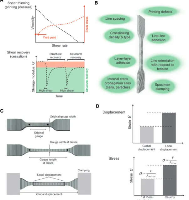
Figure 1: A schematic illustration of the important rheological and mechanical characteristics of bioprinted structures.
Rheological measurements of shear rate vs viscosity show shear thinning which is important for printability and required printing pres-sure while the meapres-surement of shear recovery (cessation) is important to evaluate shape retention post-printing (A). Bioprinting process parameters affecting the mechanical properties of the printed structures (B) and how typical hydrogel dumbbell specimens deform in tension (C) are further illustrated. Tensile properties should be calculated based on a strain derived either using global displacement (based on the distance between the grips) or local (true) displacement (measured from the video tracking of the displacement in the gage length). Furthermore, the stress can be given as 1st Piola-Kirchhoff stress (calculated using the initial cross sectional area) or as Cauchy stress (using true cross sectional area) (D). The measurements and their calculation should always be described using these terms so that studies can be compared and reproduced.
will be in the intended implantation site. Furthermore, the importance of a correct match of the deformation behav-ior of the implant material and the underlying tissue has recently been shown [8]. These properties are a func-tion of the material itself, as well as bioprinting process parameters (Figure 1B). Printed tensile specimens have been used to investigate the interaction of lines and layers [9–17], however, a systematic investigation of how process parameters influence these properties has not been con-ducted. Terminology to describe the tensile measurements include two crucial aspects. First, the displacement to cal-culate strain can be reported in terms of global or local (true) displacement (Figure 1C). The latter is the preferred value and reflects deformation of the gage length of the specimen, whereas global displacement is more suscep-tible to artifacts (e.g. slippage) and/or material deforma-tion inhomogeneities. Secondly, it is important to specify whether the stress is reported as 1st Piola-Kirchhoff stress (PK-stress = force divided by initial cross sectional area) or Cauchy stress (C-stress = force divided by current cross sectional area) (Figure 1D). The second definition of stress becomes relevant when deformations in the gage become large, leading to a significant difference between initial (reference) and deformed cross sectional area (defor-mation); e.g. in the case of hydrogels (Supplementary Figure 1). C-stress however, requires a visual acquisition of the specimen shape during the measurement, something which is not always available in tensile testing setups.
Currently the printing properties of bioinks are mainly characterized by rheology which allows the effect of sterilization, storage or batch production to be quan-tified. Additional mechanical tensile tests are required to determine how printing process parameters such as line spacing and line orientation affect structural properties of the printed constructs. Using a physically crosslinkable gellan-alginate bioink called Vivoflow, we performed a parametric study to identify and quantify the parameters with the greatest effect on mechanical properties of bio-printed structures. Furthermore, we demonstrated how these complementary material (rheology) and process related (tensile) measurements can be used to evaluate and compare bioinks. Best practice guidelines are pre-sented so that future bioink developers can evaluate their product according to common standards.
Results
A parametric study was performed with the Vivoflow bioink to investigate the most important material and
bioprinting process parameters to obtain reproducible bioprinting. As a first step, printing process parameters such as pressure, feedrate and printing height were tested to standardize the line thickness to 982 μm±92 μm (Sup-plementary Figure 2). After determination of the average line thickness, the effective line-line adhesion was inves-tigated by printing a series of bioink sheets with differ-ent line spacing (Figure 2). At all line spacings between 400–700 microns, there was a continuous overlap of the printed lines. Based on these observations, the effect of line spacing in this range on tensile properties was inves-tigated by comparing printed and cast (bulk) dumbbell samples of the same bioink. The line orientation was perpendicular to the tensile direction (transverse, 90°) to maximize the potential influence of line-line adhesion. As seen from the variance in ultimate stress, when a wider line spacing (600–700 μm) was used, some specimen broke before the sample could be mounted in the testing device. However, for the samples that could be tested, some of them were in fact as stiff as the samples printed with the smaller line spacing (400–500 μm). Similar behavior was observed for ultimate strain where nearly 50% strain was achieved with all line spacing conditions, when the test could be carried out. As illustrated in Figure 2 the most reproducible printing quality was achieved with the line spacing of 500 μm, thus all the following experiments were conducted with the dumbbell specimen printed with this line spacing.
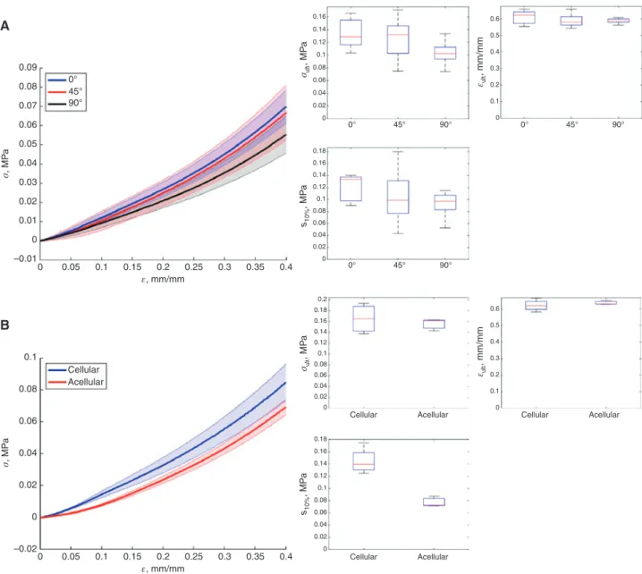
Bioprinting process allows fabrication of complex shapes which can ultimately be used in regenerative medicine as organ templates and other complex tissue replacement grafts. These complex structures will inevi-tably be exposed to forces acting in arbitrary directions, thus the printing direction should not in general affect the structural properties. A parametric investigation of print-ing direction with respect to the direction of tensile load was performed. Dumbbell specimens were printed paral-lel (0°), transverse (90°) and diagonal (45°) to the direc-tion of tensile loading. In Figure 3A no significant change in the ultimate stress (p > 0.1), ultimate strain (p > 0.1) or secant modulus (p > 0.1) was observed when the printing direction was altered, thus illustrating that the printing direction is not a significant factor in withstanding the external forces acting on the printed structures if the line spacing is optimized.
Bioinks are often tested for mechanical properties without cells, although final applications include cells. Figure 3B however, confirms that no significant difference in the ultimate stress (p > 0.1) and ultimate strain (p > 0.1) were found through addition of 6 × 10⁶ cells/mL
0.20 A B C D 0.7 0.6 0.5 0.4 0.3 0.2 0.1 0.0 0.18 0.16 0.14 Ultimate stress σult , MP a Secant modulus s10% , MP a Ultimate strain εul t , mm/mm 0.12 0.10 0.08 0.06 0.04 0.02 0.00 0.24 0.22 0.20 0.18 0.16 0.14 0.12 0.10 0.08 0.06 0.04 0.02 0.00 Bulk 400 µm 500 µm 600 µm 700 µm Bulk 400 µm 500 µm 600 µm 700 µm Bulk Bulk 400 µm 400 µm 500 µm 500 µm 600 µm 700 µm 600 µm 700 µm
Figure 2: Printed tensile specimen with increasing line spacing were compared to cast samples (bulk) to determine their mechanical properties.
(A) Ultimate stress (Cauchy), (B) ultimate strain (local) and (C) secant modulus ( < 10%) illustrate the probability of structural defects due to the printing process increased with increasing line spacing. Each point represents a tensile specimen at failure. These values are also repre-sented by boxplots where 50% of the values are in the box, the middle line represents the mean and the tails represent the highest and the lowest values. The microscopy images for each line spacing show the change in surface topography (D). Scale bar 500 μm.
secant modulus was significantly higher (p < 0.005) with cells, which might be explained by interaction of extracel-lular cations with the gellan junction zones and alginate eggbox lattice.
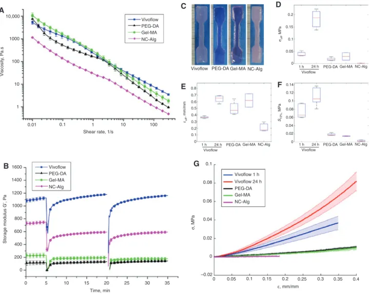
Direct comparison of bioink properties is important in order to be able to select specific inks for specific applica-tions. A standardized testing protocol consisting of rheo-logical and mechanical assessments was used to compare three commercially available bioinks to Vivoflow, which was physically crosslinked with cations for one and 24 h [14]. The commercial bioinks are referred to based on their main composition as Gel-MA (10% gelatin methacrylate [5, 18, 19] photo-crosslinked with 0.05% Ircacure I2959, BioGel from BioBots), PEG-DA (polyethyleneglycol-dia-crylate photo-crosslinked with photoinitiator, BioInk from regenHu AG, [20] and NC-Alg (1.36% nanocellulose and 0.5% alginate crosslinked with cationic solution, Cellink from Cellink) [21]. The rheological tests included shear behavior with yield point measurements (Figure 4A) and shear recovery analysis by two shear cycles (Figure 4B).
In all bioink compositions a clear shear thinning behavior was observed whereas a yield point was only observed in Vivoflow (31 Pa±2.4 Pa), Gel-MA (65 Pa±14 Pa) and NC-Alg (11 Pa±0.7 Pa). PEG-DA bioink did not have a yield point and is the only ink not designed to have shape forming and viscous fluid like properties in printing. The shear recovery behavior, i.e. bioink’s ability to recover struc-tural stability (stop flow and to withstand consecutive line printing), was high in all the bioink compositions ( > 79%). Briefly, Vivoflow and PEG-DA recovered fully ( > 99%) after shear whereas storage modulus recovery up to 79.3% in NC-Alg and 84.3% in Gel-MA was observed. Furthermore, the shape retention capability and stiffness of the Vivo-flow, Gel-MA and NC-Alg were sufficient for consecutive layer printing without intermediate crosslinking whereas the PEG-DA required crosslinking layer-by-layer.
Mechanical properties of the bulk-like printed struc-tures with the line spacing of 400 microns (Supplemen-tary Figure 3) were characterized in order to evaluate structural integrity. Figure 4F illustrates the secant
0.09 0° 45° 90° 0.08 0.07 0.06 0.05 0.04 0.03 0.02 0.01 0 –0.01 0 0.05 0.1 0.15 0.2 0.25 0.3 0.35 0.4 A B σ , MP a ε, mm/mm 0 –0.02 0.02 0.04 0.06 0.18 0.16 0.14 0.12 0.1 0.08 0.06 0.04 0.02 0 0.08 0.1 Cellular Acellular Cellular Acellular 0 0.05 0.1 0.15 0.2 0.25 0.3 0.35 0.4 σ , MP a s10% , MP a 0.18 0.16 0.14 0.12 0.1 0.08 0.06 0.04 0.02 0 0° 45° 90° s10% , MP a 0.16 0.14 0.12 0.1 0.08 0.06 0.04 0.02 0 0° 45° 90° 0° 45° 90° σul t , MP a 0.2 0.18 0.16 0.14 0.12 0.1 0.08 0.06 0.04 0.02 0
Cellular Acellular Cellular Acellular
σul t , MP a 0.6 0.5 0.4 0.3 0.2 0.1 0 εul t , mm/mm 0.6 0.5 0.4 0.3 0.2 0.1 0 εult , mm/mm ε, mm/mm
Figure 3: Tensile measurements of specimens with varying printing direction (A) and comparison of cellular and acellular specimens (B). The dumbbell specimens were printed in longitudinal (0°), transverse (90°) or diagonal (45°) orientations with respect to the tensile direc-tion. No significant differences were observed in ultimate stress (Cauchy), ultimate strain (local) or secant modulus ( < 10%) as a function of the printing direction. Furthermore, there was no significant differences in ultimate stress and strain when tensile properties of cell laden and acellular specimens were measured (6 × 10⁶ cells/mL, ~1% v/v) while a significant difference in secant modulus was observed. The shaded regions of the stress-strain curves represent standard deviations (n = 5).
modulus ( < 10%) of all the bioinks which was confirmed to be within the elastic deformation zone. Vivoflow 1 h had a significantly higher modulus compared to all the com-mercial bioinks (p < 0.01) and furthermore Vivoflow 24 h had a significantly higher modulus (p < 0.05) compared to other bioink compositions. The secant modulus of the commercial bioinks were not significantly different from each other (p > 0.05). Ultimate stress was the highest in the Vivoflow 24 h (183 kPa±36 kPa, p < 0.001) whereas the other conditions were not statistically significantly differ-ent (Vivoflow 1 h 39 kPa±8.9 kPa, Gel-MA 22 kPa±20 kPa,
PEG-DA 18 kPa±7 kPa and NC-Alg 1.4 kPa±0.2 kPa). The ultimate strain value of Vivoflow 24 h was similar to the covalently crosslinked bioinks (PEG-DA, Gel-MA) (p > 0.05) whereas the NC-Alg had a significantly lower ultimate strain value compared to Vivoflow 24 h (p < 0.005), Gel-MA (p < 0.05) and PEG-DA (p < 0.05). Summary of the secant moduli, ultimate stress and ultimate strain values for each bioink can be found in Supplementary Table 1.
The Vivoflow bioink can be tuned to match the desired tissue properties, thus the compatibility with several dif-ferent cell types can be enhanced. Tensile tests were
10,000 1000 100 10 1 0.01 0.1 1 10 Shear rate, 1/s A C D E F G B Viscosity , P a.s 100 Vivoflow PEG-DA Gel-MA NC-Alg
Vivoflow PEG-DA Gel-MA NC-Alg
0.2 0.15
0.05 0
1 h 24 h PEG-DA Gel-MA NC-Alg
Vivoflow
1 h 24 h PEG-DA Gel-MA NC-Alg
Vivoflow
1 h 24 h PEG-DA Gel-MA NC-Alg
Vivoflow 0.1 0.8 0.7 0.6 0.5 0.4 0.3 0.2 0.1 0 0.14 0.12 0.08 0.06 0.04 0.02 0 0.1 Vivoflow PEG-DA Gel-MA NC-Alg Vivoflow 24 h Vivoflow 1 h PEG-DA Gel-MA NC-Alg 1600 1400 1200 1000 800 600 400 200 0 0.1 0.08 0.06 0.04 0.02 0 –0.02 0.05 0.1 0.15 0.2 0.25 0.3 0.35 0.4 0 5 10 15 20 0 Time, min Storage modulus G’, Pa 25 30 35 σ , MP a ε, mm/mm
Figure 4: Comparison of rheological properties (A–B) and mechanical testing (C–G) of three commercial bioinks and Vivoflow bioink. Shear thinning behavior was observed in all bioink compositions (A) and shear recovery curves for all bioinks suggest high levels of recov-ery ( > 79%) (B). Printed tensile specimen (C) were mechanically tested for ultimate stress (Cauchy) (D), ultimate strain (local) (E) and secant modulus ( < 10%) (F). The average stress-strain curves for each bioink (G) are illustrated where the shaded regions represent standard deviation. Error bars (D–F) represent standard deviation. Each condition was tested with a minimum of n = 3 in rheology and n = 4 in tensile testing. Table 1: Best practices and guidelines for bioprinting.
Guidelines for optimized bioprinting
Method Action Importance (1–5)
Rheology Characterize ink by measuring shear thinning, yield point and shear recovery 5
Evaluate effect of sterilization and storage on rheology 5
Printing process
parameters Optimize the printing line dimensions by feedrate, pressure, nozzle dimension and printing heightDetermine visually the line spacing until overlap occurs 52
Investigate the percentage of line overlap for reproducible mechanical properties (where cast and
printed specimens have analogous properties) 5
Tensile tests Perform tensile testing according to standardized protocols (refer to ISO & ASTM standards) 5
Report secant modulus at 10% strain (if linear approximation is valid) 3
Report which terms and calculation (global strain or local strain and C-stress or PK-stress) are used 5
Evaluate effect of sterilization and storage on mechanical properties 3 Biocompatibility Perform viability tests for a minimum of 2 weeks and proliferation and protein synthesis assays 5
0.18 ε, mm/mm ε, mm/mm 20 mM 50 mM 100 mM 20 mM 50 mM 100 mM 0 0.16 0.14 0.12 0.1 0.08 0.04 0.06 0.02 0.6 0.5 0.4 0.3 0.2 0.1 0 0.1 0.08 0.06 0.04 0.02 0 –0.02 0 0.7 0.6 0.5 0.4 0.3 0.2 0.1 0 0 0.25 0.2 0.15 0.1 0.05 0.05 20 mM 0.3 50 mM CaCI2 SrCI2 100 mM 20 mM 50 mM 100 mM 20 mM 50 mM CaCI2 SrCI2 100 mM 20 mM 50 mM 100 mM 20 mM 50 mM CaCI2 SrCI2 100 mM 20 mM 50 mM 100 mM 0 0.25 0.2 0.15 0.1 0.05 0.1 0.15 0.2 0.25 0.3 0.35 0.4 0.5 h 1 h 3 h 6 h 12 h 24 h 0 0.18 0.16 0.14 0.12 0.1 0.08 CaCI2 SrCI2 0.06 0.04 0.02 0 –0.02 0.05 0.1 0.15 0.2 0.25 0.3 0.35 0.4 0 0.16 0.14 0.12 0.1 0.08 0.04 0.02 0.5 h 0.06 1 h 3 h 6 h 12 h 24 h 0.5 h 1 h 3 h 6 h 12 h 24 h 0.5 h 1 h 3 h 6 h 12 h 24 h A B
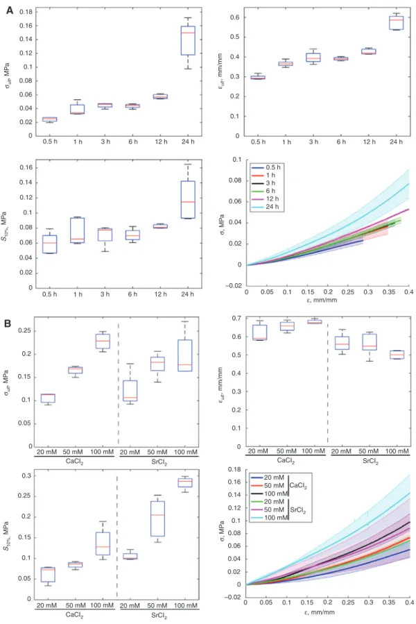
Figure 5: Mechanical properties of the Vivoflow printed structures are tunable by crosslinking time (A) and concentration and cation source (B). The mechanical properties from lowest to highest were achieved between the crosslinking conditions 20 mM SrCl2, 0.5 h and 100 mM SrCl2, 24 h. The mechanical properties can be tuned after the bioprinting process which allows more cell specific approaches. The shaded regions in the stress-strain curve represent standard deviation. Each condition was tested with five samples (n = 5). Ultimate stress (Cauchy), ulti-mate strain (local) and secant modulus ( < 10%) are represented.
performed after crosslinking with 20 mM SrCl2 for 0.5, 1, 3, 6, 12, and 24 h to investigate the crosslinking kinetics and effect on mechanical properties. The ultimate stress increased from 24 kPa±3 kPa up to 140 kPa±29 kPa with 20 mM SrCl2 during 24 h of crosslinking whereas ultimate strain increased from 30%±1% to 58%±4% in the same period. Furthermore, the tensile properties were evalu-ated after crosslinking with 20 mM, 50 mM and 100 mM strontium or calcium chloride. When the cation concen-tration was increased from 20 mM to 100 mM, the ultimate strain was not significantly different illustrating preserva-tion of the construct elasticity whereas the ultimate stress increased from 121 kPa±39 kPa to 197 kPa±51 kPa for SrCl2 and from 106 kPa±13 kPa to 228 kPa±19 kPa for CaCl2. Sim-ilarly the secant modulus increased significantly when cation concentration was increased. Similar results for pure gellan gum gels [22] and pure alginate gels [23] have been previously reported.
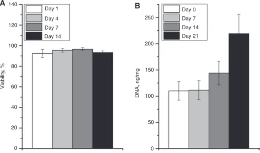
Vivoflow bioink was designed for cartilage bioprint-ing [14] and primary bovine chondrocytes were mixed into the ink prior to printing. The cell laden bioprinted struc-tures were monitored over 21 days for the changes in cell viability and amount of DNA. High cell viability ( > 93%) was observed over the whole 14 day period in vitro culture which is the minimum recommended time to observe via-bility in bioinks. Furthermore, double stranded DNA was quantified over 21 days to assess cell proliferation in the bioink. The amount of DNA doubled over 21 day culture in vitro suggesting that the bioink and bioprinting process were cell compatible.
Discussion
Bioprinting allows precise deposition of cell-laden inks in a confined 3D space. The high precision manufactur-ing process is prone to bioink- and process-related effects which can lead to variable mechanical properties and poor reproducibility. This paper evaluates and quanti-fies the mechanical properties of bioprinted structures compared to non-printed cast structures to determine the optimal printing process parameters. A systematic study was performed to investigate and to quantify the most important bioprinting process parameters in order to provide accurate process knowledge and best practices for reproducible bioprinting. Furthermore, this study pro-vides guidelines for standardized bioink testing so that future bioinks can be compared to current ones (Table 1).
The results suggest that the most important para-meters for the optimized and reproducible bioprinting processes with pneumatic printing systems are con-stant line thickness and line spacing. In fact, during pneumatically driven extrusion, slight changes in the bioink viscosity introduce flow inhomogeneities, which cause inconsistent line dimensions and line overlap and therefore decreased reproducibility. These local viscos-ity changes can be present due to bioink additives such as polymers, cells, growth factors, particles and/or entrapped air (Supplementary Figure 4). Polymer chain entanglements and molecular interactions will introduce local viscosity changes that are more frequently present in high polymer concentrations and in more complex
140 120 100 80 60 40 20 0 Day 0 Day 7 Day 14 Day 21 Day 1 Day 4 Day 7 Day 14 Viability , % DNA, ng/m g 250 200 150 100 50 0 A B
Figure 6: Biocompatibility assays performed for Vivoflow printed scaffolds.
Viability of the embedded cells (A) and DNA quantification as a measure of proliferation (B). The error bars represent the standard deviation and each condition was tested with n = 8 and n = 6, respectively.
compositions. For this reason, a minimum line overlap (%) should be used to guarantee high reproducibility of the mechanical properties. This line overlap is bioink dependent: for Vivoflow ink, a line overlap of > 48% pro-duced constant and reproducible structural properties. Furthermore, the ultimate stress and ultimate strain of the cast and the printed specimens with this line overlap percentage ( > 48%, 500 μm line spacing) were not statis-tically different. These results suggest that with an opti-mized bioprinting process and line overlap, it is possible to produce reproducible structures with comparable mechanical properties to cast structures. To minimize the line overlap the pneumatically driven extrusion systems could be replaced with the piston driven (posi-tive displacement) systems to gain a full control over the dispensing volume over time despite the presence of minor irregularities and local viscosity changes.
Production of complex tissue constructs and organ templates in the bioprinting process are rarely assessed for their mechanical integrity. Complex anatomic struc-tures cannot yet be printed with controlled mechani-cal anisotropy, thus the printing direction should not introduce differences in mechanical properties. A recent study by Compton et al. [11] described how internal fiber-reinforcement increased the mechanical properties in epoxy based materials and significant differences were reported between the transverse and longitudinal samples in tension. These differences were explained by the high aspect ratio fibers capability to bind to the polymer matrix with high pullout stress and up to nine times Young’s modulus was achieved compared to the casted polymer resin without fibers. Müller et al. investigated inkjet print-ing process parameters with photo-curable acrylic based rigid (VeroWhitePlus) and rubber-like (TangoBlackPlus) materials in alternating layers. The transverse (90°) and longitudinal (0°) printing directions were found signifi-cantly different in ultimate stress and strain values with no differences in the Young’s modulus [16]. Figure 3 illustrates the hydrogel based bioink comparison in different print-ing directions with an optimized printprint-ing process. These experiments did not show significant differences between longitudinal, diagonal and transverse testing directions for secant modulus, ultimate stress or ultimate strain, thus illustrating that the printing direction was not a significant factor. However, if the line spacing is increased beyond the recommended line overlap, differences between the print-ing directions could become significant due an increased probability of discontinuous line adhesion.
Translation of bioprinting technologies to industrial and clinical products has been limited by several draw-backs such as poor reproducibility of the printing process
and scarcity of commercial bioinks. Furthermore, the lack of standardization limits the application driven product design needed for clinical products. A standardized test protocol consisting of rheological and mechanical char-acterization was introduced for direct comparison of bioinks. All tested bioinks had shear thinning proper-ties, which is essential for cell survival during the extru-sion process, and high shear recovery behavior ( > 79%). This illustrates the material’s capacity to preserve the extrusion resolution and support layers before further crosslinking. The limited shear recovery of the Gel-MA and NC-Alg bioinks can be explained by the structural changes in the polymer components during the high shear which can result in weaker structures post-printing; however, both bioinks had sufficient recovery for consecutive layer printing without intermediate crosslinking similar to Vivoflow, whereas the PEG-DA bioink required layer-by-layer crosslinking. Mechanical comparison of current commercial bioinks revealed similarities in ultimate stress and secant modulus, while the covalently crosslinked bioinks outperformed the physically crosslinked NC-Alg in ultimate strain. Physically crosslinked Vivoflow had the highest secant modulus of all the bioinks and the overall highest ultimate stress was achieved with Vivoflow 24 h. Furthermore, the ultimate strain of Vivoflow 24 h was similar to the covalently crosslinked bioinks illustrating the strong physical crosslinking.
The Vivoflow bioink was further characterized in detail for its crosslinking-dependent mechanical (Figure 5) as well as biological properties (Figure 6). Mechanical properties were found to be highly dependent on the crosslinking conditions such as crosslinking time, con-centration and cation source. Vivoflow crosslinking was found to be time dependent, driven by the osmosis and the diffusion properties of the increasingly crosslinked matrix. The highest recorded secant modulus (283 kPa±16 kPa) and highest ultimate stress (197 kPa±51 kPa) were achieved with the 100 mM SrCl2 crosslinking for 16 h. Intermediate crosslinking properties were recorded with one h crosslinking which was also tested for the biocom-patibility with embedded chondrocytes (6 × 10⁶ cells/mL)
for tissue engineering applications. The bioink volume fraction of the cells was approximately 1% and had no significant differences in ultimate stress or ultimate strain values although a significant difference in secant modulus was observed, suggesting the cells’ ability to influence cation-polymer interactions, thus stiffening the bioink. Neither the printing process nor the crosslinking compro-mised cell viability over the 14 days observation period; in fact, during 21 days the amount of DNA had doubled in the cellular constructs illustrating good biocompatibility.
Here we systematically investigated the bioprinting process parameters to determine the optimal conditions for biocompatible printing. The influence of parameters on structural integrity was systematically evaluated and quantified for best practices (Table 1). This process-related knowledge and its influence on mechanical properties are essential for modeling, design and production of fabri-cated biological structures. Since most of the effects are related to fundamental process parameters, the results are applicable to other bioprinting setups which use extru-sion (pneumatic or displacement), microvalve-mediated and laser-based bioprinters. This paper aims to establish common standards for bioprinting process and protocols for bioink characterization which can benefit the biofabri-cation community.
Materials and methods
Gellan (Kelcogel) was purchased from CP Kelco in both high and low acetylated forms. High G content alginate was purchased from Kim-ica, Chile ltd. D-glucose was purchased from Sigma-Aldrich (Buchs, Switzerland). Dulbecco’s modified Eagle’s media (DMEM), phosphate buffered saline (PBS), fetal bovine serum (FBS), penicillin-streptomy-cin (PS), and trypsin were all purchased from Life Technologies (Zug, Switzerland). All concentrations are given in percentages weight/vol-ume (% w/v) unless otherwise indicated.
Bioink preparation
Gellan was added to D-glucose (300 mM) containing ultra-pure water at 90 °C to achieve a 3.5% solution and alginate was added to the mixture to achieve 2.5% solution. The boiling flask was kept at 90 °C with agitation until the solution was homogeneous, typically for 1 h. The homogeneous solution was cooled down to approximately 30 °C prior the cell mixing. Briefly, the bovine chondrocytes (6 × 10⁶ cells/mL) passage two were mixed in the culture medium consisting of DMEM, 10% FBS, 1% PS, 50 μg/mL ascorbic acid and 10 ng/mL of transforming growth factor beta three (TGF-β3) added to the bioink in 1:10 volume ratio whereas acellular bioink was mixed with culture medium without cells and TGF-β3 to pre-crosslink the bioink. Mix-ing was performed until the solution reached room temperature and the printing syringes were loaded. For the best printing outcome with acellular bioink, the syringes were centrifuged at 5000 rpm for 8 min for degasing.
Commercial bioinks
All commercial bioinks were purchased from the original vendors Cellink (Cellink, Sweden), BioInk (RegenHU, Switzerland) and Bio-Gel (BioBots, US). The inks were prepared according to manufac-turer’s protocols and recommendations except in BioGel where a
common photoinitiator, Ircacure® 2959 in cytocompatible 0.05% concentration [24, 25], was used instead of the one provided by the vendor. Bioinks were crosslinked with two different methods: photo-crosslinked (BioInk and BioGel) and physically crosslinking via cati-ons (Vivoflow, Cellink). Photo-crosslinking was performed for 1 min following each layer and finally for 5 min to complete the crosslink-ing whereas the cation initiated bioinks were crosslinked post print-ing for 10 min with Cellink kit crosslinkprint-ing solution and 1 h or 24 h for Vivoflow (20 mM SrCl2).
Printing syringes of the bioinks were mounted onto the extru-sion printer Biofactory® (RegenHU, Switzerland) and the parameters were set for 410 micron straight nozzle diameter. BioInk (P:50–125 kPa, valve opening time 200 μs) and Cellink (P:35 kPa, valve opening time 1200 μs) were printed according to manufacturer’s recommenda-tions using pneumatic microvalves whereas BioGel was printed with a direct extrusion system as suggested by the manufacturer similar to Vivoflow. Bioinks were printed longitudinal (0°) in sheet conforma-tion (4 cm length, 1 cm width and 1.5 mm height) to prevent printing related stress localization and to prevent process related bias in the mechanical testing. Immediately following the printing, the tension dumbbells were transferred into sterile petri dishes containing either the crosslinking medium (Cellink and Vivoflow) or culture medium (BioInk, BioGel). Following the physical crosslinking all the sam-ples were kept in culture medium for 48 h to allow uniform swelling before the tensile specimens were stamped according to ISO 527-2-5B standard. In the results, the commercial inks are referred to by their composition: BioInk = PEG-DA, BioGel = Gel-MA, Cellink = NC-Alg.
Rheology
An Anton Paar MCR 301 (Anton Paar, Zofingen, Switzerland) rheometer equipped with a Peltier element for temperature control and a thermostatic hood was used to measure the bioinks (before crosslinking) to determine shear and recovery responses by simulat-ing the bioprintsimulat-ing. Shear thinnsimulat-ing was analyzed in rotation with a plate-cone geometry (50 mm diameter) by measuring viscosity η at a frequency of 1 rad s−1 with a logarithmic increase of the shear rate. Yield points were calculated using the Herschel/Bulkley equation
HB c p τ τ= + ⋅ γ
where τ is shear rate, τHB is the Herschel/Bulkley yield point, c flow coefficient, γ p shear stress with exponent p, where p is the Herschel/Bulkley index (p < 1 for shear thinning and p > 1 for shear thickening). Cessation of flow was measured for each bioink in oscillation with a frequency of 1 rad/s and 1% strain for 15 min sequence until a 1 s lasting high shear (100−s) sequence was per-formed followed by oscillation and second high shear sequence. All the rheology measurements were performed at 25 °C corresponding to the printing at room temperature and all the measurements were measured in triplicates.
Mechanical testing
Mechanical testing was performed by considering the guidelines and standards for elastomers and plastics in tensile measurements (ASTM D412-06a, ASTM D638-14, ISO 37, ISO 527-1,2) as well as
standards for biomedical and regenerative medicine (ASTM F2064-14, ASTM F2900-11, ASTM F2150-13) relevant for the mechanical test-ing. Bioinks were printed in sheet conformation (4 cm length, 1 cm width and 1.5 mm height) to prevent printing related stress localiza-tion and inaccurate sample sizes. The sheets were kept in culture medium for 24 h for uniform swelling and the dumbbell specimens were stamped according to ISO 527-2-5B standard. The cast bioink sheets (bulk) were similarly stamped. Each specimen was imaged with a stereomicroscope (Wild M650, Leica) to calculate the initial gage dimensions where the average height and width were averaged over three sample positions (Supplementary Figure 5). Tension test-ing was performed with a custom-made testtest-ing device with uniaxial hydraulic actuators equipped with 100 N load cells. Custom-made titanium clamps equipped with sandpaper were used for specimen fixation. The tensile specimens were clamped to the retracting probes without preloading and the stress-strain curves were recorded after a 0.005 N–0.01 N pre-force was reached. Samples were subjected to a controlled tensile displacement of 0.1 mm s−1 until failure in a saline bath (NaCl, 154 mmol/L) at room temperature. Local (true) strains were determined from images of the deforming specimens (time lapse) via point tracking with a custom-written code [26] or similarly using an ImageJ plugin trackmate. Both 1st Piola-Kirchhoff (σpK1) and Cauchy (σC) stresses were computed for each specimen according to the following relations: σpK1 = Fc/(w0t0), and σC = Fc/(wctc), F being the measured force throughout the tensile test, w the specimen width, and t its thickness where the subscripts 0 and c refer to the initial (reference) and the current (deformed) configurations, respectively. Each specimen dimensions (width and thickness) were measured using a stereomicroscope (Wild M650, Leica) initially (reference) and the poisson ratio was analyzed from the local deformation tracking to simulate the thickness changes during the deformation (deformed). Secant modulus was calculated within the linear region of the stress-strain curve by dividing the corresponding stress value by the 10% strain. A linear region was observed until 10% strain for all the tension samples where the secant modulus highly correlates with the Young’s modulus. Ultimate stress was always calculated using Cauchy stress equation and ultimate strain was always determined from the local deformation. These ultimate values were obtained as the highest values of the stress-strain curves which were recorded until 0.5% decrease in the stress was detected to neglect any disrup-tion related forces.
Acknowledgments: The work was funded by the
Swiss National Science Foundation (grant number CR32I3_146338/1) and FIFA/F-MARC. Authors would like to thank Prof. André Studart, Complex Materials, ETH Zurich for use of equipment.
Author’s statement
Conflict of interest: Authors state no conflict of interest. Materials and methods
Informed consent: Informed consent has been obtained
from all individuals included in this study.
Ethical approval: The research related to human use has
been complied with all the relevant national regulations, institutional policies and in accordance the tenets of the Hel-sinki Declaration, and has been approved by the authors’ institutional review board or equivalent committee.
References
1. Chhaya PM, Poh SP, Balmayor RE, van Griensven M, Schantz J-T, Hutmacher WD. Additive manufacturing in biomedical sciences and the need for definitions and norms. Expert Rev Med Devices. 2015;12:537–43.
2. Malda J, Visser J, Melchels PF, Jüngst T, Hennink EW, Dhert JW, et al. 25th anniversary article: engineering hydrogels for biofabrication. Adv Mat. 2013;25:5011–28.
3. Billiet T, Van Gasse B, Gevaert E, Cornelissen M, Martins CJ, Dubruel P. Quantitative contrasts in the photopolymerization of acrylamide and methacrylamide-functionalized gelatin hydrogel building blocks. Macromol Biosci. 2013;13:1531–45.
4. Aguado B, Mulyasasmita W, Su J, Lampe K, Heilshorn S. Improving viability of stem cells during syringe needle flow through the design of hydrogel cell carriers. Tissue Eng Part A. 2012;18:806–15.
5. Billiet T, Gevaert E, De Schryver T, Cornelissen M, Dubruel P. The 3D printing of gelatin methacrylamide cell-laden tissue-engineered constructs with high cell viability. Biomaterials. 2014;35:49–62.
6. Khalil S, Sun W. Bioprinting endothelial cells with alginate for 3D tissue constructs. J Biomec Eng. 2009;131:1–8.
7. Tirella AO, Vozzi G, Ahluwalia A. A phase diagram for microfabri-cation of geometrically controlled hydrogel scaffolds. Biofabri-cation. 2009;1:1–12.
8. Mazza E, Ehret EA. Mechanical biocompatibility of highly deformable biomedical materials. J Mech Behav Biomed Mat. 2015;48:100–24.
9. Bakarich S, Balding P, Gorkin R, Spinks GM, In het Panhuis, M. Printed ionic-covalent entanglement hydrogels from carra-geenan and an epoxy amine. RSC Adv. 2014;4:38088–92. 10. Bakarich S, Gorkin R, In Het Panhuis M, Spinks GM.
Three-dimensional printing fiber reinforced hydrogel composites. ACS Appl Mater Interfaces. 2014;6:15998–6006.
11. Compton GB, Lewis AJ. 3D-Printing of lightweight cellular com-posites. Adv Mat. 2014;26:5930–5.
12. Cui J, Lackey M, Madkour EA, Saffer ME, Griffin MD, Bhatia RS, et al. Synthetically simple, highly resilient hydrogels. Biomacro-mol. 2012;13:584–588.
13. Hong S, Sycks D, Chan H, Lin S, Lopez PG, Guilak F, et al. 3D printing of highly stretchable and tough hydrogels into complex, cellularized structures. Adv Mat. 2015;27:4035–40.
14. Kesti M, Eberhardt C, Pagliccia G, Kenkel D, Grande D, Boss A, et al. Bioprinting complex cartilaginous struc-tures with clinically compliant biomaterials. Adv Func Mat. 2015;25:7406–17.
15. McKee TC, Last AJ, Russell P, Murphy JC. Indentation versus tensile measurements of young’s modulus for soft biological tissues. Tissue Eng Part B. 2011;17:155–64.
16. Mueller J, Shea K, Daraio C. Mechanical properties of parts fabricated with inkjet 3D printing through efficient experimental design. Mater Des. 2015;86:902–12.
17. Wei J, Wang J, Su S, Wang S, Qiu J, Zhang Z, et al. 3D printing of an extremely tough hydrogel. Roy Soc Chem Adv. 2015;5:81324–9. 18. Hoch E, Schuh C, Hirth T, Tovar ME, Borchers K. Stiff gelatin
hydrogels can be photo-chemically synthesized from low vis-cous gelatin solutions using molecularly functionalized gelatin with a high degree of methacrylation. J Mat Sci Mater Med. 2012;23:2607–17.
19. Schuurman W, Levett P, Pot WM, Van Weeren RP, Dhert AJ, Hutmacher WD, et al. Gelatin-methacrylamide hydrogels as potential biomaterials for fabrication of tissue-engineered cartilage constructs. Macromol Biosci. 2013;13:551–61. 20. Rimann M, Bono E, Annaheim H, Bleisch M, Graf-Hausner U.
Standardized 3D bioprinting of soft tissue models with human primary cells. J Lab Autom. 2015;1–14.
21. Markstedt K, Mantas A, Tournier I, Martinez Avila H, Hägg D, Gatenholm P. 3D bioprinting human chondrocytes with nanocellulose–alginate bioink for cartilage tissue engineering applications. Biomacromol. 2015;16:1489–96.
22. Grasdalen H, Smidsrød O. Gelation of Gellan Gum. Carbohyd Polym. 1987;7:371–93.
23. Mørch AY, Donati I, Strand LB, Skjak-Braek G. Effect of Ca2+, Ba2+, and Sr2+ on alginate microbeads. Biomacromol. 2006;7:1471–80.
24. Bryant JS, Nuttelman RC, Anseth SK. Cytocompatibility of UV and visible light photoinitiating systems on cultured NIH/3T3 fibroblasts in vitro. J Biomat Sci Polymer Edn. 2000;11:439–57. 25. Williams GC, Malik NA, Kim KT, Manson NP, Elisseeff HJ. Variable
cytocompatibility of six cell lines with photoinitiators used for polymerizing hydrogels and cell encapsulation. Biomat. 2005;26:1211–8.
26. Hopf R, Bernardi L, Menze J, Zündel M, Mazza E. Experimental and theoretical analyses of the age-dependent large-strain behavior of Sylgard 184 (10:1) silicone elastomer. J Mech Behav-ior Biomed Mat. 2016;60:425–437.
Supplemental Material: The online version of this article (DOI: 10.1515/bnm-2016-0004) offers supplementary material, available to authorized users.