Publisher’s version / Version de l'éditeur: Building Practice Note, 1985-12-01
READ THESE TERMS AND CONDITIONS CAREFULLY BEFORE USING THIS WEBSITE.
https://nrc-publications.canada.ca/eng/copyright
Vous avez des questions? Nous pouvons vous aider. Pour communiquer directement avec un auteur, consultez la
première page de la revue dans laquelle son article a été publié afin de trouver ses coordonnées. Si vous n’arrivez pas à les repérer, communiquez avec nous à [email protected].
Questions? Contact the NRC Publications Archive team at
[email protected]. If you wish to email the authors directly, please see the first page of the publication for their contact information.
NRC Publications Archive
Archives des publications du CNRC
For the publisher’s version, please access the DOI link below./ Pour consulter la version de l’éditeur, utilisez le lien DOI ci-dessous.
https://doi.org/10.4224/20337925
Access and use of this website and the material on it are subject to the Terms and Conditions set forth at
Shear resistance of wood frame walls
Hansen, A. T.
https://publications-cnrc.canada.ca/fra/droits
L’accès à ce site Web et l’utilisation de son contenu sont assujettis aux conditions présentées dans le site LISEZ CES CONDITIONS ATTENTIVEMENT AVANT D’UTILISER CE SITE WEB.
NRC Publications Record / Notice d'Archives des publications de CNRC:
https://nrc-publications.canada.ca/eng/view/object/?id=ed84a682-d8f8-4b54-b947-3a5175d8222f https://publications-cnrc.canada.ca/fra/voir/objet/?id=ed84a682-d8f8-4b54-b947-3a5175d8222f
SHEAR RESISTANCE OF WOOD FRAME WALLS
by A.T. Hansen
Technical Information Group
Division of Building Research
BPN 61
Ottawa, December 1985
@National Research Council Canada 1985
zyxwvutsrqponmlkjihgfedcbaZYXWVUTSRQPONMLKJIHGFEDCBA
ABSTRACT
zyxwvutsrqponmlkjihgfedcbaZYXWVUTSRQPONMLKJIHGFEDCBA
For over fifty years, many agencies have been performing racking tests on wood frame walls to determine their shear resistance. The racking strength of walls is derived from the inte- rior finish as well as the exterior sheathing and siding. This is discussed in the context of Canadian tests which eventually led to the deletion of building code requirements for brac- ing and sheathing. Comparisons between Canadian and U.S. test results indicate generally reasonable agreement with certain materials, while others show substantial differences. Allowable shear values given in US model building codes are summarized. Mathematical models for computing racking strength from the lateral strength characteristics of fasteners are discussed. Design aids for computing the shear resistance of wood frame walls are noted.
RESUME
Depuis plus de cinquante ans, plusieurs organismes ont effectud des essais de ddformation diagonale de murs ossature de bois afin de ddterminer leur rdsistance au cisaillement. La rdsistance des murs la dkformation diagonale dkpend des revetements intdrieur, in- termddiaire et extdrieur. Cette question est dtudide ici dans le contexte des essais cana-
diens qui ont abouti
zyxwvutsrqponmlkjihgfedcbaZYXWVUTSRQPONMLKJIHGFEDCBA
h la suppression des exigences du code du btitiment en matihre decontreventement et de revetement. La comparaison des rdsultats des essais canadiens et amhricains rdvde que l’on s’entend assez bien sur certains matdriaux, mais beaucoup moins sur d’autres.
On ddcrit les contraintes admissibles en cisaillement dktermindes dans les codes moddes du btitiment aux Etats-Unis. On ddcrit aussi des moddes mathdmatiques pour calculer
la rCsistance
zyxwvutsrqponmlkjihgfedcbaZYXWVUTSRQPONMLKJIHGFEDCBA
h la ddformation diagonale a partir de la rdsistance des attaches aux effortstransversaux. Finalement, on fait mention d’aides
zyxwvutsrqponmlkjihgfedcbaZYXWVUTSRQPONMLKJIHGFEDCBA
ii la conception pour le calcul de laINTRODUCTION
zyxwvutsrqponmlkjihgfedcbaZYXWVUTSRQPONMLKJIHGFEDCBA
Under Canadian building codes, houses and many small buildings of conventional wood frame construction are not required to be individually analyzed for structural sufficiency. This is because they are considered to have sufficient inherent strength to resist normal forces when constructed in conformity with specified rule-of-thumb practice. As a re-
sult, much less design attention is paid to such buildings, particularly to their ability to withstand wind and seismic forces.
In the case of larger buildings (over three storeys or with a floor area greater than 600
zyxwvutsrqponmlkjihgfedcbaZYXWVUTSRQPONMLKJIHGFEDCBA
m2),individual structural analysis is required. Similarly, buildings used to house inmates or patients (institutional type), for gatherings of people (assembly type) or with extreme fire hazards are required to be structurally analyzed regardless of the size of the building. Lack of accepted performance data for conventional wood frame construction, however, may make design compliance difficult to establish, particularly in relation to wind and seismic effects.
The increasing use of insulating sheathing materials in place of structural sheathing has in many cases removed a significant component of racking resistance that may have been taken for granted. This loss is especially significant during construction before the interior wall finish is in place. Without temporary bracing the building is vulnerable to damage from wind forces. An awareness of the contribution of each component in resisting racking forces is, therefore, important in order to avoid failures.
The purpose of this paper is to review existing information on the racking resistance of wood frame construction in order to give designers an appreciation of the shear strength of wood frame walls.
RACKING TESTS
Racking tests to measure the resistance of walls to wind and seismic forces were initiated many years ago by the Forest Products Laboratory of the U.S. Department of Agricul- ture 111. Since that time many other agencies in various countries have carried out similar tests and many papers have been published describing this work 121. However, variations in wall panel size, construction details, and wood species, as well as methods of testing, frustrate attempts to compare many of these results.
Generally, tests have followed a standard method published by the American Society for Testing and Materials designed to compare the relative performance of sheathing mate- rials [3]. Most racking tests consisted of applying incremental loads to the top of a test
wall specimen approximately 2400
zyxwvutsrqponmlkjihgfedcbaZYXWVUTSRQPONMLKJIHGFEDCBA
x 2400 mm in size (Figure 1 ) . To satisfy the require-ments of the standard to compare sheathing materials only, restrictions are placed on the wood species, stud spacing and boundary conditions, and the tests are limited to sheathing diaphragms. These limitations have led to the development of another method (also by
HOLD-DOWN FORCE
TO PREVENT OVERTURNING
zyxwvutsrqponmlkjihgfedcbaZYXWVUTSRQPONMLKJIHGFEDCBA
I
RACKING&
FORCEzyxwvutsrqponmlkjihgfedcbaZYXWVUTSRQPONMLKJIHGFEDCBA
2400 x 2400zyxwvutsrqponmlkjihgfedcbaZYXWVUTSRQPONMLKJIHGFEDCBA
mm TEST PANEL #zyxwvutsrqponmlkjihgfedcbaZYXWVUTSRQPONMLKJIHGFEDCBA
//A/////‘//.
’/ /SUPPORTING BASE
zyxwvutsrqponmlkjihgfedcbaZYXWVUTSRQPONMLKJIHGFEDCBA
Figure 1 Typical test panel.
zyxwvutsrqponmlkjihgfedcbaZYXWVUTSRQPONMLKJIHGFEDCBA
RACKING FORCE
LENGTH
zyxwvutsrqponmlkjihgfedcbaZYXWVUTSRQPONMLKJIHGFEDCBA
OF PANEL SHEAR =v
of how the wall will perform in a building. The direct application of the measured values to building design must, therefore, be done with some caution.
CANADIAN TESTS
Canadian tests were carried out in the 1950’s by both the National Research Council’s Division of Building Research and the Forest Products Research Branch (now Forintek
Canada Corporation). Table 1 is based on these tests
zyxwvutsrqponmlkjihgfedcbaZYXWVUTSRQPONMLKJIHGFEDCBA
[5]. Prior to these studies, itwas normal practice to brace exterior walls unless they were sheathed with plywood, al- though fibreboard and gypsum board sheathing were allowed without bracing on one-storey houses 161. Bracing was required to extend across three stud spaces and usually consisted
of a 19 x 89 mm board notched into the studs. Horizontal lumber sheathing with brac- ing became a standard for comparison since this was most representative of traditional practice.
Tests showed that horizontal lumber sheathing, even when combined with bracing, did not contribute as much to the strength and stiffness as the interior finishing materials. A t a displacement of 13 mm, which is perhaps the limit of acceptable distortion, such bracing and sheathing contributed only 20 to 30% of the total strength. The remainder was due to the interior finish. On complete houses the exterior walls carry only part of racking forces. The partitions which are normally fastened to the ceiling diaphragm also carry part of the total racking force (Figure 2). The contribution of sheathing and bracing to the total racking strength would be somewhat less, therefore, than that indicated by tests on the exterior walls only.
Figure
zyxwvutsrqponmlkjihgfedcbaZYXWVUTSRQPONMLKJIHGFEDCBA
2zyxwvutsrqponmlkjihgfedcbaZYXWVUTSRQPONMLKJIHGFEDCBA
Shear forces due to wind on a typical house. These tests led to the conclusion that bracing and sheathing were not necessary to resistracking forces where the interior was finished (although sheathing may be necessary as a nailing base or support for some siding materials). This decision is reflected in current
Canadian building code requirements
zyxwvutsrqponmlkjihgfedcbaZYXWVUTSRQPONMLKJIHGFEDCBA
171. As a result, very few Canadian racking testshave been carried out since the 1950’s. Although most wood frame buildings continue to be sheathed, this is primarily to permit rapid protection from the weather and, in the case
of insulating sheathings, to reduce heat loss. Tradition, however, is also considered to be
a significant factor in retaining sheathing.
EFFECT OF INTERIOR FINISH ON RACKING RESISTANCE
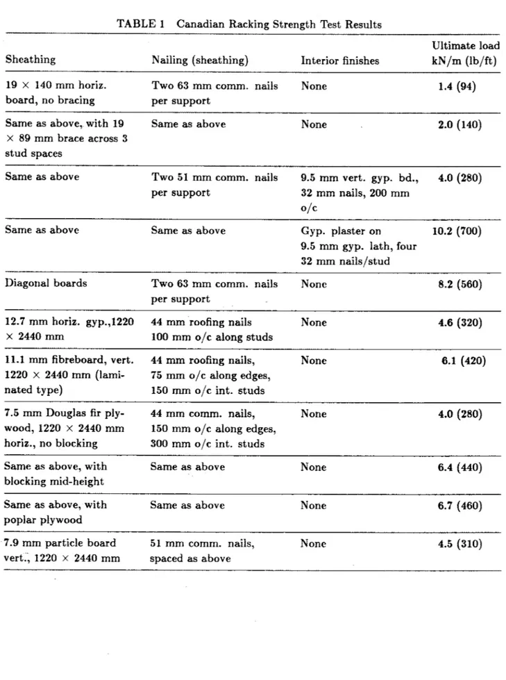
Although not commonly considered as a structural component, interior finish does in fact .contribute substantially to the racking resistance of buildings. According to Table 1,
gypsum lath and plaster increased the ultimate shear load of braced lumber-sheathed walls by five times, while gypsum wallboard doubled it even though the latter was attached only
to the studs.
Tests by the National Association of Home Builders Research Institute on typical partitions (12.7 mm gypsum board on both sides of studs spaced 610 mm o/c) indicated an ultimate
load of 7.2 kN/m (500 lb per lineal ft), or about 3.6 kN/m for each membrane
zyxwvutsrqponmlkjihgfedcbaZYXWVUTSRQPONMLKJIHGFEDCBA
[ 8 ] . Morerecent tests by the U.S. Forest Products Laboratory
zyxwvutsrqponmlkjihgfedcbaZYXWVUTSRQPONMLKJIHGFEDCBA
[9] indicated that a gypsum wallboardhowever, a different test method 141 was used than was the case in earlier tests and the framing was of the spruce-pine-fir group rather than Douglas fir. This study also indicated that racking resistance per unit length of wall was not linear, but increased with greater lengths. Values based on tests of short wall lengths, therefore, were conservative when applied to longer walls. Wallboard orientation was also significant. When wall lengths
were increased to three times the wall height, horizontally applied gypsum wallboard gave almost twice the shear resistance as the vertically applied board, presumably due to the greater average distance of the nails from the cut edges of the board.
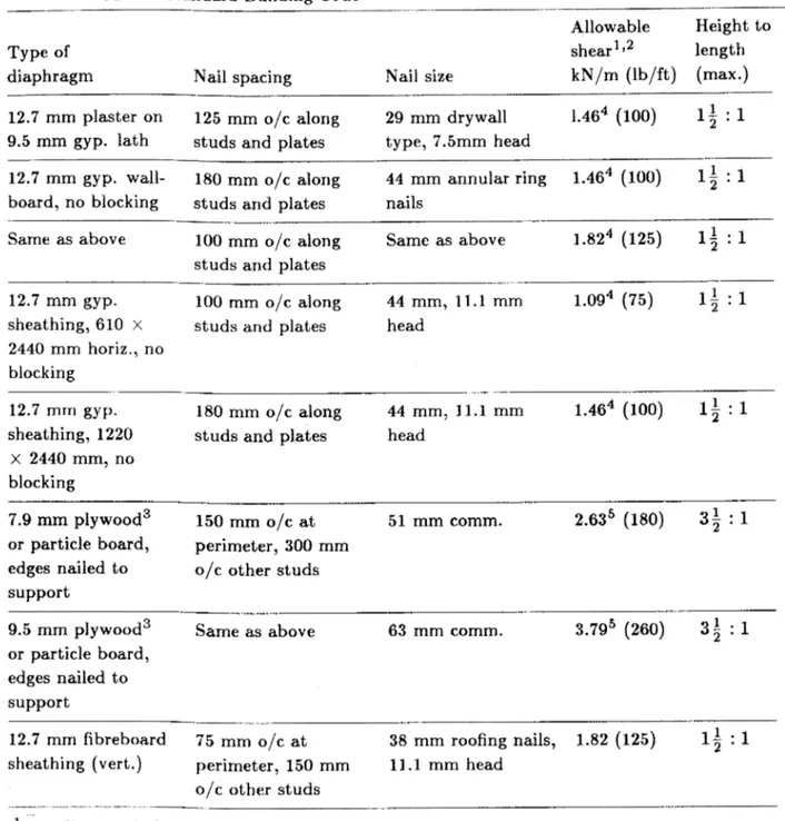
The ICBO Uniform Building Code
[lo]
and the SBCCI Standard Building CodezyxwvutsrqponmlkjihgfedcbaZYXWVUTSRQPONMLKJIHGFEDCBA
[
111 are ingeneral agreement regarding the maximum allowable shear values for vertical diaphragms sheathed with gypsum wallboard, gypsum sheathing or plaster. These are summarized in
Table
zyxwvutsrqponmlkjihgfedcbaZYXWVUTSRQPONMLKJIHGFEDCBA
2. The BOCA Basic Building Code [12] includes similar data but this is includedfor information in its appendix. These values are apparently based in part on tests carried out a number of years ago by the Armour Research Foundation
[
131.EFFECT OF SHEATHING AND BRACING ON RACKING RESISTANCE
Table 1 indicates that horizontal lumber sheathing contributes relatively little to the strength of walls having an interior finish. In the case of braced horizontal lumber sheath- ing, however, the U.S. Department of Housing and Urban Development has accepted a
value of 9.5 kN/m (650 lb per lineal ft) where the bracing consists of 19 x 89 mm lumber installed a t a 45" slope. This has been used as one of the criteria in assessing proprietory sheathings in the U.S. since 1949 [14]. While diagonal lumber provides considerably greater racking resistance to walls than horizontal lumber, this is seldom used in Canada.
A braced panel without sheathing according to one series of tests has an approximate ultimate strength of 5.8 kN/m (400 lb/ft) [15]. This is an average value based on tests incorporating different species of U.S. pine bra.cing installed a t a 45" slope (in compression), and is considerably higher than indicated in Canadian tests where the bracing extended across only three stud spaces.
Although no published data were found to indicate the racking resistance of foamed plastic
or glass fibre insulating sheathings, their strength characteristics indicate that this resis- tance would be small. Some tests have incorporated insulating sheathings in combination with other materials, however
[
161.Vertical fibreboard sheathing (Table 1) has an ultimate strength of 6.1 kN/m (420 lb/ft). American tests on 12.7 mm average density sheathing are in fairly good agreement, indi-
cating an average ultimate strength of about
zyxwvutsrqponmlkjihgfedcbaZYXWVUTSRQPONMLKJIHGFEDCBA
6.3 kN/m (440 lb/ft)[
151.Plywood sheathing is available in a variety of species and thicknesses, and may be applied vertically or horizontally, with different nail spacings, and with or without blocking a t the joints between sheets, all of which affect its racking resistance. According to Table 1, the ultimate strength values for panels with 7.5 mm plywood vary from 4.0 to 6.7 kN/m (280 to
460
zyxwvutsrqponmlkjihgfedcbaZYXWVUTSRQPONMLKJIHGFEDCBA
lb/ft), with the lower value applying to horizontally applied plywood with no blocking a t mid-wall height. Tests by the U S . Forest Products Laboratory on panels sheathed with6 mm Douglas fir plywood with different sizes and spacings of framing members indicate ultimate strengths of from 10.4 to 11.4 kN/m (712 to 782 lb/ft) [17]. These higher values are probably due to a number of factors, including larger nail sizes, closer nail spacing and the use of Douglas fir framing. The manner in which the tests are carried out can also affect the ultimate strength. If, for example, the sheathing is allowed to be in contact with the supporting base, considerably higher values can result. Extensive testing has also been
carried out by the American Plywood Association and data from this work as well
zyxwvutsrqponmlkjihgfedcbaZYXWVUTSRQPONMLKJIHGFEDCBA
as datafrom the U.S. Forest Products Laboratory and the Oregon Forest Research Center have provided the basis for the current design of plywood diaphragms in the U.S. [18].
Panels with vertically applied 7.9 mm particle board have an ultimate strength of
zyxwvutsrqponmlkjihgfedcbaZYXWVUTSRQPONMLKJIHGFEDCBA
4.5 kN/m(310 lb/ft) (Table 1). More recent Canadian tests (unpublished) with 7.9 mm waferboard indicate an average ultimate strength of 5.7 kN/m (390 lb/ft). Another source, however, shows the ultimate strength to be 10.2 kN/mIn (700 lb/ft) 1191. The reason for these differences is not, known.
Both the ICBO Uniform Building Code
[lo]
and the SBCCI Standard Building Code 1111list allowable shear values for exterior walls for certain sheathing materials. When values are given in both codes these also are in basic agreement. Selected abstracts from the two codes for a number of typical sheathing membranes are shown in Table 2, along with values for gypsum wallboard and plaster. Some caution should be exercised in applying these values to design problems, however. Table 2 does not give all the qualifying conditions for the use of these values, nor does it list all of the systems covered in the model codes. Those who wish to use these values for design guidance should consult the codes directly
to ensure that the values are used appropriately. The materials used for sheathing or
for interior wall cladding in Table 2 are assumed to conform to the appropriate product standard referenced in the model codes as well. While the BOCA Basic Building Code does not include allowable shear values for wood frame walls, provision is made for their design in conformance with accepted engineering practice.
GENERAL CONSIDERATIONS IN COMPUTING SHEAR RESISTANCE
The design values for shear resistance often cannot be determined by simply adding to- gether the values for the individual membranes in a wall system, although in the case of
partitions which have identical membranes on both sides, this can be done. If the load- deflection characteristics of each membrane component in a wall are known, a reasonable approximation of the total load required to reach a given deflection can also be determined. Unless the membranes fail at the same deflection limit, however, it is usually not possible to determine the total ultimate strength by adding the ultimate loads for individual mem- branes. If the membranes fail in sequence, the total strength may be no stronger than the strongest membrane in the assembly.
Normally, in calculating the shear resistance, only the wall portions that are continuous from floor to ceiling are considered. Portions containing doors or windows are usually
ignored. The minimum lengths of solid segments are also restricted in the
zyxwvutsrqponmlkjihgfedcbaZYXWVUTSRQPONMLKJIHGFEDCBA
US.
modelcodes by maximum height-to-length ratio limits. These range from I f
zyxwvutsrqponmlkjihgfedcbaZYXWVUTSRQPONMLKJIHGFEDCBA
: 1 tozyxwvutsrqponmlkjihgfedcbaZYXWVUTSRQPONMLKJIHGFEDCBA
3; : 1depending on the membrane, and how it is installed. Presumably this is to ensure that rotation of the segment will not occur before the shear strength of the wall is developed.
SHEAR RESISTANCE IN RELATION TO LATERAL
NAIL
STRENGTHBecause of the almost limitless combinations of materials, species, stud spacing, fastener spacing, membrane thickness, stud size, fastener size, and type of fastener (all of which can affect racking strength), it is practically impossible to determine the shear resistance in each case by testing full size wall panels. Even though tests have been in progress for over half a century, information on many combinations is lacking.
In recent years increasing attention has been given to developing analytical methods to determine racking resistance. Although the empirical relationship between the racking strength and the lateral resistance of nails in sheathing has been appreciated for some time [20], it was only a relatively few years ago that a method was developed for computing racking strengths that could be applied to various sizes of panels with symmetrical nailing patterns and sheathed with various materials [21]. The method assumes that as walls deflect, the individual sheathing panels tend to retain their rectangular shape while the framing assumes a rhomboid shape. The resulting change in nail location between the two causes an absorption of energy at the fasteners. The input needed to calculate shear resistance with this method is the panel geometry, the number and spacing of nails, and the lateral strength resistance characteristics of the nails attaching the sheathing to the framing.
Where the sheathing is installed vertically, and the nailing is spaced symetrically, the total racking resistance (R) due to perimeter nailing can be expressed as
2
zyxwvutsrqponmlkjihgfedcbaZYXWVUTSRQPONMLKJIHGFEDCBA
a 2 - 1 b 2 - 13 a -cos
zyxwvutsrqponmlkjihgfedcbaZYXWVUTSRQPONMLKJIHGFEDCBA
a+
~ sin2 a ) ]zyxwvutsrqponmlkjihgfedcbaZYXWVUTSRQPONMLKJIHGFEDCBA
+
kb R = n . s . s i n a [ a + b - -(---
where
n = number of sheathing panels
s = ' maximum lateral strength of an individual nail
a = angle between the vertical and diagonal of each panel a = number of nail spaces along each horizontal panel edge
b = number of nail spaces along each vertical panel edge
This proceedure can be modified to allow for the nailing along intermediate studs, but since
the perimeter nailing contributes about
zyxwvutsrqponmlkjihgfedcbaZYXWVUTSRQPONMLKJIHGFEDCBA
95% of the total racking resistance for commonsheathing, the additional complication does not appear to be warranted.
An extension of this method has been proposed which assumes that the sheathing panels
act as a series of springs extending diagonally from corner to corner of each panel
zyxwvutsrqponmlkjihgfedcbaZYXWVUTSRQPONMLKJIHGFEDCBA
[22]. Bydetermining the stiffness modulus of the assumed springs, based on the fastener spacing and load-deflection characteristics of an individual fastener, and knowing the size and modulus elasticity of the framing members, the racking characteristics of different panel configurations can be determined. This model can be adapted to apply to taped gypsum
board panels as well, where the entire wall tends to act as a single panel
zyxwvutsrqponmlkjihgfedcbaZYXWVUTSRQPONMLKJIHGFEDCBA
[9]. It is beyondthe scope of this paper, however, t o detail the various calculation methods, and the reader is directed to the references at the end of this paper for additional details.
DESIGN AIDS FOR CALCULATING SHEAR DIAPHRAGMS
Many useful publications are available to assist in the design of wood frame shear walls as well as horizontal diaphragms. These are chiefly concerned with the more traditional structural materials such as lumber and plywood sheathing.
Information on the design of plywood shear walls and horizontal diaphragms in the
U.S.
(and to some extent in Canada), is for the most part based on design procedures developed
by the American Plywood Association
zyxwvutsrqponmlkjihgfedcbaZYXWVUTSRQPONMLKJIHGFEDCBA
[
181. This work also forms the basis for the allowableshear values specified for plywood in two of the U.S. model codes and in American manuals
on wood design such as The Timber Construction Manual of the American Institute of Timber Construction [23].
The design of diaphragms incorporating lumber sheathing is described in detail in a pub- lication of the Western Wood Products Association [24], and has also formed the basis for the design procedures for such diaphragms described in manuals on wood design, such as the AITC manual previously mentioned.
In Canada, the Canadian Wood Council and the Council of Forest Industries of British Columbia have issued special publications to assist designers of shear walls and horizontal diaphragms
[
25,261, and Forintek Canada Corporation has developed a computer pro- gramme as a further refinement to the design process 1271.CONCLUSION
The wealth of information in the literature attests to the extent that the subject of wall racking strength has been investigated, and current literature indicates that it is still being actively investigated. This paper does not pretend to cover the subject thoroughly. Its intent is merely to acquaint the designer with some of the background work in this area. The problem facing the designer may not be so much a lack of information for proper design execution as. an excess of information from which to choose.
Canadian building codes do not as yet specify allowable shear values for shear walls and horizontal diaphragms as do certain U.S. codes, nor is there a nationally adopted standard in this field. The designer, therefore, must exercise professional judgement in dealing with this subject to ensure structural sufficiency in those types of wood frame buildings that
are required to be individually designed.
zyxwvutsrqponmlkjihgfedcbaZYXWVUTSRQPONMLKJIHGFEDCBA
REFERENCES
1. Trayer, G.W. The Rigidity and Strength of Frame Walls. Report No. R896, U.S. Dept. of Agriculture Forest Service, Forest Products Laboratory, Madison, WI, 1929.
2. Carney, J.M. Bibliography on Wood and Plywood Diaphragms, Journal of the Struc- tural Division, American Society of Civil Engineers, Vol. 101, No. ST11, pp. 2423- 2436, 1975.
3. Standard Methods of Conducting Strength Tests of Panels for Building Construction.
Designation E72-80, American Society for Testing and Materials, Philadelphia, PA.
zyxwvutsrqponmlkjihgfedcbaZYXWVUTSRQPONMLKJIHGFEDCBA
4. Standard Method of Static Load Test for Shear Resistance of Framed Walls for Build- ings. Designation E564-76, American Society for Testing and Materials, Philadel- phia, PA.
5. Hansen A.T. Results of Tests to Determine Racking Resistance of Walls. Technical Note 376, National Research Council Canada, Division of Building Research, Ottawa, June 1962.
6. Building Standards (Excluding Apartment Buildings). Canada Mortgage and Hous- ing Corporation, CM8, Ottawa, May 1955.
7. National Building Code of Canada, 1985. Associate Committee on the National Building Code. National Research Council Canada, NRCC 23174, Ottawa, 1985.
8. Racking Strengths and Stiffnesses of Exterior and Interior Frame Wall Constructions, Vol. 2, National Association of Home Builders Research Foundation Incorporated. Report PB-234 909, Rockville, MD, May 1971.
9. Wolfe, R.W. Contribution of Gypsum Wallboard to Racking Resistance of Light-
zyxwvutsrqponmlkjihgfedcbaZYXWVUTSRQPONMLKJIHGFEDCBA
.
Frame Walls. U.S. Dept. of Agriculture Forest Service. Forest Products Laboratory Research Paper FPL 439, Madison, WI, December 1983.
10. Uniform Building Code. International Conference of Building Officials. Whittier, GA, 1985.
11. Standard Building Code. Southern Building Code Congress International. Birming- ham, AL, 1985.
12. BOCA Basic Building Code. Building Officials and Code Administration Interna-
tional. Homewood, IL, 1981.
zyxwvutsrqponmlkjihgfedcbaZYXWVUTSRQPONMLKJIHGFEDCBA
13. Armour Research Foundation Report No. ARF K1037, Illinois Institute of Technol- ogy, Chicago, IL, May 1966.
14. A Standard for Testing Sheathing Materials for Resistance to Racking. Technical
Circular No. 12, Federal Housing Administration, Washington, DC, October 1949. 15. Tuomi, R.L., and Gromala, D.S. Racking Strength of Walls: Let-in Corner Bracing,
Sheet Materials, and Effect of Loading Rate. U.S. Dept. of Agriculture Forest Service. Research Paper FPL 301, Forest Products Laboratory, Madison, WI, 1977. 16. Wolfe, R. W. Racking Performance of Plywood-over-foam-insulation Wall Construc- tion, U.S. Department of Agriculture Forest Service, (Draft Report PB84-208404) Forest Products Laboratory, Madison, WI, September 1982.
17. Luxford, R.F., and Bonser, W.E. Adequacy of Light Frame-Wall Construction. U.S. Dept. of Agriculture Forest Service, Report No. 2137, Forest Products Laboratory, Madison, WI, November 1958 (Revision).
18. Carney, J.M. Plywood Diaphragm Construction
zyxwvutsrqponmlkjihgfedcbaZYXWVUTSRQPONMLKJIHGFEDCBA
- APA-U310, American PlywoodAssociation, Tacoma, WA, 1976.
19. Jessome, A.P. Canadian Waferboard Properties - 1979. Forintek Canada Corpora- tion, Eastern Laboratory Technical Report 5233, Ottawa, 1979.
20. Neisel, R.H., and Guerrera, J.F. Racking Strength of Fibreboard Sheathing. Tech- nical Association of the Pulp and Paper Industry. TAPPI Vol. 39, No. 9, Sup. New York, NY, February 1956.
21. Toumi, R.L., and McCutcheon, W.J. Predicting Racking Strength of Light Frame Walls. American Society for Civil Engineers Preprint 2934. San Francisco, CA, October 1977.
22. Itani, R.Y., Toumi, R.L., and McCutcheon, W.J. Methodology to Evaluate Racking Resistance of Nailed Walls. Forest Products Journal, Vol. 32, No. 1, 1982.
23. Timber Construction Manual, American Institute of Timber Construction, Engle- wood, CO, Second edition, 1974.
24. Degenkolb, H.J., and Wyllie, L.A. Western Woods Use Book, Western Wood Prod- ucts Association, Portland, OR, 1973.
25. Shear Walls and Diaphragms, Wood Design on Construction Data File WC-1, Cana- dian Wood Council, Ottawa, 1979.
26.
zyxwvutsrqponmlkjihgfedcbaZYXWVUTSRQPONMLKJIHGFEDCBA
Douglas Fir Plywood Diaphragms, Council of Forest Industries of British Columbia, Vancouver, 1979.27. Foschi, R.O. Computer Program for Structural Analysis of Diaphragms and Trusses
zyxwvutsrqponmlkjihgfedcbaZYXWVUTSRQPONMLKJIHGFEDCBA
TABLE
zyxwvutsrqponmlkjihgfedcbaZYXWVUTSRQPONMLKJIHGFEDCBA
1 Canadian Racking Strength Test Results Ultimate loadSheathing Nailing (sheathing) Interior finishes kN/m (lb/ft)
19
zyxwvutsrqponmlkjihgfedcbaZYXWVUTSRQPONMLKJIHGFEDCBA
x 140 mm horiz. Two 63 mm comm. nails None 1.4 (94)board, no bracing per support
Same as above, with 19 Same as above None 2.0 (140)
X 89 mm brace across 3
stud spaces
Same as above Two 51 mm comm. nails 9.5 mm vert. gyp. bd., 4.0 (280)
per support 32 mm nails, 200 mm o/c
Same as above Same as above Gyp. plaster on
~~
10.2 (700) 9.5 mm gyp. lath, four
32 mm nails/stud
Diagonal boards Two 6 3 mm comm. nails None 8.2 (560)
per support
12.7 mm horiz. gyp.,1220 44 mm roofing nails None 4.6 (320)
X 2440 mm 100 mm
zyxwvutsrqponmlkjihgfedcbaZYXWVUTSRQPONMLKJIHGFEDCBA
o / c along studs11.1 mm fibreboard, vert. 44 mm roofing nails, None 6.1 (420) 1220 x 2440 mm (lami-
nated type)
7.5 mm Douglas fir ply-
zyxwvutsrqponmlkjihgfedcbaZYXWVUTSRQPONMLKJIHGFEDCBA
44 mm comm. nails, None 4.0 (280)wood, 1220 X 2440 mm horiz., no blocking
75 mm o/c along edges,
150 mm o / c int. studs
150 mm o/c along edges,
300 mm o/c int. studs
Same
zyxwvutsrqponmlkjihgfedcbaZYXWVUTSRQPONMLKJIHGFEDCBA
as above, with Same as above None 6.4 (440)blocking mid-height
Same as above, with Same as above None 6.7 (460)
poplar plywood
7.9 mm particle board 51 mm comm. nails, None 4.5 (310)
TABLE
zyxwvutsrqponmlkjihgfedcbaZYXWVUTSRQPONMLKJIHGFEDCBA
2 Selected Allowable Shear Strengths from the ICBO Uniform Building Code and the SBCXI Standard Building CodeAllowable Height t o
Type of shear'
zyxwvutsrqponmlkjihgfedcbaZYXWVUTSRQPONMLKJIHGFEDCBA
j 2 lengthdiaphragm N a i l spacing Nail size kN/m (lb/ft) (max.)
zyxwvutsrqponmlkjihgfedcbaZYXWVUTSRQPONMLKJIHGFEDCBA
~~
1.464 (100) 1 2 I :
zyxwvutsrqponmlkjihgfedcbaZYXWVUTSRQPONMLKJIHGFEDCBA
112.7 mm plaster on 125 mm o/c along
9.5 mm gyp. lath studs and plates type, 7.5" head
12.7 mm gyp. wall- 180 o/c along 44 mm annular ring 1.464 (100) 1; : 1
board, no blocking studs and plates nails
Same as above 100 mm o/c along Same as above 1.824 (125) 1; : 1
29 mm drywall studs and plates
100 mm o/c along 1.0g4 (75) 1, 1 : 1
12.7 mm gyp.
sheathing, 610 x studs and plates head
2440 mm horiz., no blocking
44 mm, 1 1 . 1 mm
12.7 mm gyp. 180 mm o/c along 44 mm, 11.1 mm 1.464 (100)
zyxwvutsrqponmlkjihgfedcbaZYXWVUTSRQPONMLKJIHGFEDCBA
I f : 1sheathing, 1220 studs and plates head
x 2440 mm, no blocking
7.9 mm plywood3 150 mm o/c at 51 mm comm.
or particle board, perimeter, 300 mm edges nailed to o/c other studs support
9.5 mm plywood3 Same as above 63 mm comm. 3.7g5 (260) 3 $ : 1
or particle board, edges nailed to support
12.7 mm fibreboard 75 mm O/C at
sheathing (vert.) perimeter, 150 mm 11.1 mm head
O / C other studs
2.635 (180) 35 1 : 1
38 mm roofing nails, 1.82 (125) 1, 1 : 1
Applies to wind and seismic loads only.
Values shown are for studs spaced 400 mm o/c. Plywood grade - CD, CC, Structural 11.
Values can be doubled if identical material is used on both sides.
Values are for Douglas fir, larch and southern pine. Reduction factor of 0.82 for group 111 and