Publisher’s version / Version de l'éditeur:
ASTM Special Technical Publication, 718, pp. 57-76, 1980
READ THESE TERMS AND CONDITIONS CAREFULLY BEFORE USING THIS WEBSITE.
https://nrc-publications.canada.ca/eng/copyright
Vous avez des questions? Nous pouvons vous aider. Pour communiquer directement avec un auteur, consultez la première page de la revue dans laquelle son article a été publié afin de trouver ses coordonnées. Si vous n’arrivez pas à les repérer, communiquez avec nous à PublicationsArchive-ArchivesPublications@nrc-cnrc.gc.ca.
Questions? Contact the NRC Publications Archive team at
PublicationsArchive-ArchivesPublications@nrc-cnrc.gc.ca. If you wish to email the authors directly, please see the first page of the publication for their contact information.
NRC Publications Archive
Archives des publications du CNRC
This publication could be one of several versions: author’s original, accepted manuscript or the publisher’s version. / La version de cette publication peut être l’une des suivantes : la version prépublication de l’auteur, la version acceptée du manuscrit ou la version de l’éditeur.
Access and use of this website and the material on it are subject to the Terms and Conditions set forth at
Glass fiber as insulation and drainage layer on exterior of basement
walls
Tao, S. S.; Bomberg, M. T.; Hamilton, J. J.
https://publications-cnrc.canada.ca/fra/droits
L’accès à ce site Web et l’utilisation de son contenu sont assujettis aux conditions présentées dans le site LISEZ CES CONDITIONS ATTENTIVEMENT AVANT D’UTILISER CE SITE WEB.
NRC Publications Record / Notice d'Archives des publications de CNRC:
https://nrc-publications.canada.ca/eng/view/object/?id=2b45ee5f-fe0b-42c9-8b33-e09c31ca6cc8 https://publications-cnrc.canada.ca/fra/voir/objet/?id=2b45ee5f-fe0b-42c9-8b33-e09c31ca6cc8
n.0.
970
National Research Conseil nationalI c. 2
I
$
Council Canada de recherches CanadaGLASS FIBER AS INSULATION A N D
DRAINAGE LAYER O N EXTERIOR OF
BASEMENT WALLS
by S.S. Tao. M. Bomberg and J.J. Hamilton
Reprinted from
Thermal Insulation Performance
American Society for Testing and Materials
L I B R A R Y
Special Technical Publication 718. 19801
B I B L ~ O T H ~Rech. 86ti r r . w . < c
-
IC DBR Paper No. 970Division of Building Research
P o u r a s s u r e r l a p r o t e c t i o n d e s s o u s - s o l s c o n t r e 11humidit6 e t l e f r o i d , on a posd d e s panneaux de f i b r e d e v e r r e d e f o r t e densitd 'a l ' e x t d r i e u r d e deux s o u s - s o l s prototypes. Cette couche d ' i s o l a t i o n e t de d r a i n a g e peut f a c i l e m e n t Btre adaptde aux rnhthodes d e c o n s t r u c t i o n a c t u e l l e s e t l e coat n ' e s t pas t r o p dlevd. L1efficacitd du panneau d e f i b r e d e v e r r e d e 140 k g / m 3 p o s d v e r t i c a l e m e n t s o u s l a s u r f a c e fut contr6lde. L e s p r e m i e r s r d s u l t a t s f u r e n t e n c o u r a g e a n t s . On a con- s t a t 6 une bonne r d p a r t i t i o n d e llhumiditd e t une r e s i s t a n c e s u f f i s a n t e 'a l a c o m p r e s s i o n . Apr'es deux a n s s o u s t e r r e , l ' i s o l a n t a v a i t toujours une r h s i s t a n c e t h e r m i q u e s i t u d e e n t r e 22,6 e t 26,8 ~ " c / w . Nous e s t i m o n s qulune couche d ' i s o l a - tion e t de d r a i n a g e peut p r o t d g e r l e s o u s - s o l c o n t r e l1humidi- th, f o u r n i r une m e i l l e u r e i s o l a t i o n t h e r m i q u e e t p e r m e t t r e un m e i l l e u r v i e i l l i s s e m e n t d u b6ton. Avec c e r t a i n s p e r f e c - tionnements, l'idde e s t valable e t m d r i t e une etude plus a p - profondie, v o i r e l a c o m m e r c i a l i s a t i o n . L a p r d s e n t e c o m - munication d d c r i t l e s mdthodes d l i n s t a l l a t i o n , l e s i n s t r u - m e n t s d e contrBle e t l e s quelques r d s u l t a t s obtenus d a n s deux s o u s - s o l s e x p d r i m e n t a u x contrBles p a r l a D i v i s i o n d e s r e c h e r c h e s s u r l e b t t i m e n t du CNRC depuis 1967.
Authorized Repint from Journal of Special Technical Publication 718
-m.
American Society for Tesbng and Materiab 1916 Race Street, Philadelphia, Pa. 19103
S.
S.
Tao,
M.
Bomberg, and
J. J.
Hamilton'
Glass Fiber as Insulation and
Drainage Layer on Exterior of
Basement Wal Is
ANALYZED
REFERENCE: Tao. S. S.. Bomberg, M.. and Hamilton. J. J., bbGhrr Fiber am Inrub-
thn and Drainage Layer on E a c h of Basement W&" Thermal Insulation Perfor- mance, ASTM STP 718. D. L. McElroy and R. P. Tye, Eds., American Society for Testing and Materials, 1980, pp. 57-76.
ABX!iRAm To provide combined moisture and thermal protection for basements, high-density glass fiberboard was used on the exterior of two prototype basements. This insulation-drainage layer can easily be adapted to current construction procedures and the cost is not excessively high. Performance of the 140-kg/m3 (9 Ib/ft3) glass fiber- board installed vertically below grade was monitored. Early results are encouraging. Favorable moisture distribution and compressive deformation were found. After two years of burial the insulation still maintained a thermal resistivity that ranged from 22.6 to 26.8 m-OC/W. It is believed that the concept of an insulation-drainage layer has the potential to keep the basement dry, to provide improved thermal insulation. and to enable better curing of concrete. With refined design details the concept is at- tractive and worthy of continued study and development. This paper describes methods of installation, monitoring instruments, and some findings obtained from two experi- mental basements monitored since 1976 by the Division of Building Research/National Research Council of Canada.
KEY WORDS: thermal insulation, basement insulation, thermal resistance, heat transmission, fibrous material, glass fiber, mineral fiberboard, moisture, moisture con- tent, basement wall, drainage
+
Recent changes in thermal standards have encouraged Canadian house builders to explore inexpensive, efficient methods of insulating basement walls. Surveys conducted by the Housing and Urban Development Associil- tion of Canada (HUDAC) and the National Home Builders' Association (NHBA) have consistently shown a high incidence of dampness and water leakage problems in basements. Over longer periods of performance, homeowners and researchers have confirmed that problems become more'National Research Council of Canada, Division of Building Research, Prairie Research Station. Saskatoon. Saskatchewan, Canada.
THERMAL INSULATION PERFORMANCE
prevalent as basements grow older. Conventional exterior dampproofing has not prevented these problems, and after-the-fact repairs have tended to be very costly and often ineffective. Insulations placed on the inside (be- tween framing and covered with a vapor barrier and gypsum board or ' wood lining) do not protect the concrete from low temperatures or soil moisture and they are difficult to protect with complete vapor barriers.
Methods of improving drainage and drying of concrete and masonry basement walls were pioneered by Scandinavian researchers. Edvardsen [112 investigated the use of glass fiberboard as a drainage layer and a capillary break. He concluded that the material he had used, 50 kg/m3 (3 Ib/ft3), was completely satisfactory for these dual purposes. Elmroth and Hoglund [2], experimenting with mineral wool on the outside of concrete walls, reported that mineral fiberboard 5 cm (2 in.) thick and of 150-kg/m3 (9 Ib/ft3) den- sity performed well thermally and reduced moisture levels.
In Canada the Mark IX experimental house, completed in 1972 in Regina, Sask., incorporated a variety of insulations on its corrugated steel basement
[3-51.
Most of the steel walls were covered with expanded poly- styrene on the outside, but in some sections 9-mm-thick (3/8 in.) glass fi- berboard was used. Recent inspection has shown that the insulations are essentially dry and the steel panels rust-free after five years. Hamilton [61 also has reported the use of 50-kg/m3 (3 Ib/ft3) glass fiber insulation on the outside of a preserved wood basement in northern Quebec.In the search for a solution to both insulation and drainage problems of basement walls, the Prairie Regional Station (PRS), Division of Building Research/National Research Council of Canada (DBR/NRC), is monitor- ing the performance of high-density glass fiberboards on the exterior of cast-in-place concrete basements in Saskatoon. It has been postulated that a high-density insulation board often used in built-up roofing could fulfill both drainage and thermal needs and provide other benefits as well. This paper describes the method of i.nstallation, the monitoring instruments, and some preliminary findings.
Objectives
f Field investigations to evaluate several aspects of the performance, eco- nomics, and practicability of outside insulation on basement walls were
carried out in the following areas: 4
1. maintenance of insulating properties through several seasons,
2. effectiveness of glass fiber as a drainage layer in keeping groundwater from entering basements,
3. ground temperatures and ground freezing conditions adjacent to walls,
TAO ET AL ON GLASS FIBER 59
4. reaction of insulation material to earth pressures and field moisture conditions,
5. evaluation of practical aspects of construction and maintenance that may be attributable to external insulation, and
6. cost-benefit performance of the systems.
Meadow Green Subdivision, House 1
(619 Avenue W., Saskatoon)
This is a typical project bungalow of 97-m* (1040 ft2) plan area with cast-in-place concrete footings, basement walls, and floor. The soil on site is dry, relatively well-drained and fine-grained aeolian sand. Although foot- ing levels are many feet above the current water table, it is possible that the groundwater level may rise following urban development and the base- ment is therefore provided with conventional weeping tiles and washed gravel surround. The remainder of the backfill is uncompacted native soil.
A single layer of rigid fiber insulation was applied on the outside of the concrete wall, as shown in Fig. 1. Polystyrene insulation [51 mm (2 in.)] was set behind the floor joist header prior to beam filling during concrete wall casting. ("Beam filling" is a common method of joining cast-in-place concrete walls to main floor joists west of the Great Lakes in Canada. By embedding the floor joists in the top of foundation walls, the need for anchor bolts is eliminated.) Following removal of concrete forms, nailing strips were installed at two elevations. The upper one, atsfloor level, con- sists of 41 by 241-mm (2 by 10 in. nominal) planks, and the lower one, at 1.8 m (6 ft) above the footing, is made of 41 by 41-mm (2 by 2 in. nominal) treated lumber. Figure 2 shows the actual arrangement of various compo- nents.
Backfilling around the basement was carried out on 5 March 1976, and the house was completed in April and occupied in October of the same year. Until July 1978 no landscaping had been carried out and the ground around the house had experienced only normal precipitation and roof run- off.
As a first field prototype, the house was fitted with 51-mm-thick (2 in.) glass fiber insulations of four different densities above grade, namely, 50, 70, 110, and 140 kg/m3 (3, 4.5, 7, and 9 Ib/ft3); two different densities were used below grade, 110 and 140 kg/m3 (7 and 9 Ib/ft3). Because of its structural characteristics, however, only the 140-kg/m3 (9 Ib/ft3) insula- tion was instrumented for long-term monitoring. Forty-two thermocouples were placed in two vertical sections to give profiles of temperature from the inside wall surface to 2.1 m (7 ft) into the adjacent soil. They are located at the centerline of the north and west walls. The west test section is currently under continual observation, and the north section serves as a backup. For each, three water detectors (Retawmatic Corp. Model 402) were placed at
60
THERMlAL INSULATION PERFORMANCE 2 - 3 8 m m x 250 m m H E A D E R S G L A S S FIBER O F VARIOUS DENSITIES 50 m m EXPANOE 3 8 m m x 38 m m T R E A T E D POLYSTYRENE 4 G L A S S FIBER O F VARIOUS DENSITIES n-
I S C A L E mFIG. 1-Cross-sectiotrul view oj busemetrt wull. House I .
the concrete-insulation interface at elevations 750 and 150 mm (30 and 6 in.) above the footing as well as at the top of the footing. These detectors
r
can detect the presence of water if the insulation is saturated for more than
Y4 h.
In March 1977 a heat flow meter was mounted on the inside of the north
*
wall 750 mm (30 in.) below outside grade. It was specially assembled and carefully calibrated in the same arrangement as was used for testing. ATNO
Type WS31[ A
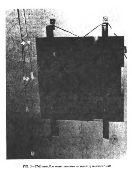
heat flow meter, 106 mm (4 in.) in diameter, was cast in the center of a 600-mm-square (24 in.), 9-mm-thick (0.35 in.) silicon rubber mat. Plexiglas of the same size was used to press the heat flow me- ter against the wall (Fig. 3). Information for thermal resistance calcula- tions was recorded by a multipoint chart recorder.TAO ET AL ON GLASS FIBER 61
-
. c & ? r r w . . v s l r p r-
,
--.*
,*
-
..
. -FIG. 2u-Nailing strips and f i m i n g urourrd busemerrt wirrdow. House 1.
The 140-kg/m3 (9 Ib/ftJ) glass fiber used in this experimental basement was tested in the laboratory using a constant-head method for determining water permeability coefficient. The results given in Table 1 indicate that this material has permeability comparable to that of a clean sand and gravel mixture.
Wildwood
Subdivision, House2
(1214
McKercher Dr., Sashtoon)!
This house is the same model of bungalow as the Meadow Green one. The soil profile in the Wildwood area shows 1.2 m (4 ft) of sandy loam underlain by silty clay, with 5 percent sand, 60 percent silt, and 35 percent clay. Natural soil moisture content on a dry-weight basis was in the range 30 to 40 percent during excavation. As the house is located near the low point of a long, gently sloping terrain, water collected from a large area will drain from the back of the house to the front. The exterior drainage and thermal insulation on the basement walls are shown in Fig. 4, and dif- fer from those of House 1 (Fig. 1) in the following:
62 THERMAL INSULATION PERFORMANCE
1. The upper nailing strip along the floor header is made up of 38 by 89- mm (2 by 4 in. nominal) wood and a strip of plywood 8 mm ( 9 1 6 in.) thick, bringing total thickness to about 46 mm to accommodate two layers of glass fiber insulation (Fig. 5).
2. Rigid glass fiberboards covering the whole wall have dimensions 1830
,
by 610 by 38 mm (6 ft by 2 ft by 1.5 in.) and density of 140 kg/m3 (9 Ib/ ft3). The 1830-mm (6 ft) length and 610-mm (2 ft) width expedite applica- tion and eliminate below-grade horizontal joints.3. Another layer of glass fiber insulation was applied to the upper half of the wall, where a minimum resistance of 1.48 m2 m°C/W (8.4 ft2 h-OF/Btu) is required.
4. Above grade, glass fiber insulation was covered with expanded metal- lath reinforced stucco parging.
A complete list of instrumentation installed in this basement is given in Table 2.
Five heat flow meters (two kinds) were installed on the west wall of the house, where moisture conditions are expected to be severe. One mounted on the inside of the concrete wall was the same as that described for House
FIG. 26-ltrstullutiotr oj' gluss Jiiber itrsulatiotr utrd jinishirig with asbestos-cemetrt board. House I .
TAO ET AL ON GLASS FIBER 63
FIG. 3-TNO heatflow meter mourrted otr itaside of'busemetrt wall.
1: On the outside, the heat flow meters consisted of calibrated 140-kg/m3- density (9 Ib/ft3) glass fiberboards either sealed in polyethylene bags or open to the backfill soil. The sealed and unsealed sections were placed at the same depth (Fig. 6a) to indicate any effect of moisture entrapment in
the drainage layer.
Any indication of change in moisture level of the insulation was provided by an electrical resistance moisture meter (Delmhorst DC-1 Moisture
THERMAL I N S U L A T I O N P E R F O R M A N C E
TABLE 1- Water permeability of' 140-kg/m 19 lb/ft -') glass fiber insulation.
Direction of Flow Head, cm Permeability, cm/s
Perpendicular to board 10.7 0.62 0.63 0.63 21.2 0.61 0.59 0.61 31.4 0.58 0.59 0.61 * Avg = 0.61 Parallel to board Avg = 1.04 E X T E R I O R S T U C C O F I N I S 8 m m S H E A T H I N G 8 m m P L Y W O O D S T R I P G L A S S F I B E R B O A R D C R A n J E 38 m m i 18 m m T R E A T E D W O O D N A I L I N G S T R I P
,
,,
;00 G L A S S m m F I B E R B O A R D W I D E 0-
I S C A L E , mTAO ET AL ON GLASS FIBER 65
a
FIG. 5-Insulation attached to wall by stickpins. House 2.
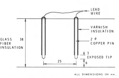
Indicator) recalibrated for the glass fiber material. Two lines of moisture pins, one at the center of the west wall and the other at the northwest cor- ner near a roof drainage downspout, were implanted in the insulation (Fig. 66). The two 610-mm-wide (2 ft) glass fiberboards with moisture pins were fitted with water-collected pans draining separately into two collection bottles in an accessible sump below the basement floor (Fig. 6c).
66 THERMAL INSULATION PERFORMANCE
TABLE 2-Instrumentation installed at House 2.
Moisture Pins
to laonitor change in moisture content
at different strata in the insulation 12 pairs
Water Collecting Pans and Collection Bottles 2 sets I
Total Earth Pressure Cells
to measure earth pressures trasmitted through
the insulation:
Gloetzl cells Geonor cell Plate Compression Gages
t o measure insulation c o m p ~ v i o n Thermocouples
to measure ground and wall temperature dis- tribution:
west wall test section 26
south wall test section 12
Heat Plow Meters
TNO Type WS31
unsealed, calibrated glass fiber insulation with thermocouples
sealed, calibrated glass fiber insulation with thermopiles
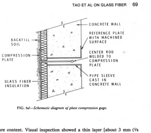
with the wall surface. Three insulation plate compression gages were in- stalled at the same elevations, offset approximately 300 mm ( - 12 in.) laterally from the pressure cells. These are used to measure compression of the insulation from the inside of the basement. A rod passing through a hole in the concrete wall transfers any movement of a metal plate on the outside surface of the insulation to a dial gage on the inside of the wall (Fig. 6 4 .
Construction of this house began in October 1976 and the basement was backfilled in November. Until July 1978 the house was still not occupied, I but the heating system has been in full operation since January 1977 and a mean temperature of 19OC has been maintained in the basement.
Installation and Backfilling
Application of glass fiber insulation on the outside of the two experi- mental basements required only slight modification of conventional proce- dures. The insulation panels were secured to the wall either by nailing to
TAO ET AL ON GLASS FIBER 67
FIG. 60-Exterior heut f b w meters. House 2.
horizontal strapping or by the use of stickpins and fitted snugly to the top of the footing. This seemingly temporary attachment resisted downdrag during backfilling and subsequent settlement of backfill.
. At the Wildwood house, although large chunks of frozen soil were pushed into the excavation, the insulation did not suffer any noticeable damage from backfilling. To date there has been no sign of cracking or distress of the parging to indicate any problem of downdrag.
@
WERWk9L INSULATION PERFORMANCE G L A S S 38 F I B E R I N S U L A T I O N I N S U L A T I O N'
C O P P E R P I N A L L DIMENSIONS I N m mFIG. 6b-Moisture pins used wtrh Dclmhorsr DC-1 morsrure urdtcuror.
B O T T L E
FIG. 6c-Schemutrc drugrum oj wuter-coIIectirrg syslem.
I
Moisture Measurements
A core sample of insulation was taken at the Wildwood house on 15 July
1977 from 60 cm (24 in.) below grade, following 8 months of burial.
Moisture content determination of the outer 6 mm (Y4 in.) on either side
indicated that the side in contact with concrete had attained 2.1 percent moisture by volume; the side in contact with soil had attained 1.2 percent.
The center portion of the core was essentially dry, with only 0.5 percent
B A C K F I L L S O I L C O M P R E S S I O N P L A T E G L A S S F I B E R I N S U L A T I O N C O N C R E T E W A L L R E F E R E N C E P L A T E W I T H M A C H I N E D S U R F A C E C E N T E R R O D
.
W E L D E D T O C O M P R E S S I O N P L A T E P I P E S L E E V E C A S T I N C O N C R E T E W A L LFIG. W-Schernuric diugrurn of'pkute cotnyrrssiott guge.
moisture content. Visual inspection showed a thin layer [about 3 mm (Y8
in.)] of very wet insulation in contact with the wall.
Moisture pins were also used to assess the wetness of material. These pins, however, provide only an approximate measure because the calibra- tion constant can change in time owing to electrochemical interaction. The moisture distribution indicated by these pins was similar to that deter- mined by direct measurement in July 1977. The moisture content measured at 150 mm (6 in.) above the footing was approximately 9 percent.
During snow melt and rainfall, the moisture content in the glass fiber temporarily increased. For the panel near a roof downspout, the bottom portion attained a moisture content of 21 percent by volume after heavy rain and the water collecting system registered a water flow of 20 cm3/min (1.22 in.J/min).
Compression of Insulation
r Compression tests were performed in the laboratory on four glass fiber insulation specimens, all of 140-kg/m3 (9 Ib/ft3) density. They were first tested at air-dry condition. An elapsed time of one day was allowed for each load, except for the maximum load of approximately 20 kPa (3 psi), under which specimens were allowed to compress for one week. Unloading was carried out in a different manner. Instead of waiting for a day after each load removal, the next load was taken off when rebound ceased. The 140-kg/m3 (9 lb/ftJ) dry glass fiber insulation regained most of its original
70 THERMAL INSULATION PERFORMANCE
thickness after one cycle of loading and unloading. Permanent deformation at the end of this cycle was found to be within 1.5 percent.
After the dry test, the same specimens were completely soaked and com- +
pressed in water, following the same loading and unloading schedule. Stress-strain curves for each specimen varied somewhat, but they all fall
into the two bands shown in Fig. 7. Also plotted in Fig. 7 are in situ com-
.
pression data given by the plate compression gages and pressure cells. The in situ data showed considerable difference in compression with depth. Most points given by the upper gage fell below the dry test band. This may
be attributed to the poor resolution of the pressure cells and to the fact
that pressure and compression are not measured at exactly the same loca- tion in the field. The points given by the lower gage are all within the wet test band, indicating a predictably larger amount of strain for wet insula- tion. Compression measured in situ is less than 9 percent at the bottom and less than 5 percent at other depths.
I
Ground Temperatures !
Temperature measurements show that the amount of insulation applied to the basement wall does not cause adfreezing or frost heaving. Although the accumulated freezing index had reached 942 degree-days (Celsius) on 21 January 1977 and there was very little snow cover on the ground near the house, the frost line intersected the wall at only about 0.3 m below grade (Fig. 8). This is probably an indication that heat losses through the wall are still high, and suggests that more insulation could safely be used, especially for the top part of the basement wall. As observed in another in- stallation with natural snow cover in Saskatoon, virtually horizontal ground temperature isotherms can develop if a basement wall has an R-value of 3.8 m2-"C/W (21.5 ft2 .hSoF/Btu) to 60 cm (-24 in.) below grade and the remainder R = 1.5 mZ-OC/W (8.5 ft2.he°F/Btu).
Thermal Resistivity of ~nsulation
The method used for determining the resistance of basement insulation ,
in situ has been described [8]. Basically, the heat flux and temperature differentials are summed over a period of time and their resistance is calcu-
lated according to long-term summations. Table 3 gives the values of heat
,
flux and temperature differentials obtained at House 2 for the period from November 1977 to March 1978. Measurements were made at a depth of 1 m (40 in.) below outside grade; the long-term average thermal resistivity for the last 5 months of the 17-month burial period was 26.8 ma°C/W (3.87 ft*-hs°F/Btu-in.). Laboratory tests performed on air-dry glass fiber insulation of the same material as used in House 2, using the ASTM Test for Steady-State Thermal Transmission Properties by Means of the Guarded Hot Plate (C-177-76), gave a resistivity value of 29 m."C/W (4.2
I
TAO ET AL ON GLASS FIBER 71 S T R E S S . p s i 0.75 m BELOW GRADE A 1.2 m BELOW GRADE 1.62 m BELOW GRADE m LA 0.2 rn ABOVE FOOT1 NG-
S T R E S S , k P aFIG. 7-Compressiorr of' 140-kg/t11 ( 9 lb/irr:') gluss fiberbourd us observed irr luborurory urtd irr field. Luborutoty resl resulls ore represerrred by the two burrds.
I
f t 2 - h
.
"F/Btu. in.). Measurements were repeated in House 2 in November 1978 and yielded a heat flux similar to those reported in Table 3 for No- vember 1977. At House 1, where measurements were made at 0.75 m be-r low grade, the thermal resistivity for the four months ending the 2-year burial period averaged 22.6 m."C/W (3.26 ft2-h-OF/Btu-in.). See Table 4.
Cost Estimates
It was difficult to estimate expenditures related to applying insulation to the basement, particularly labor cost, because the application method was new and the instruments had to be placed as the work progressed. There is
72 THERMAL INSULATION PERFORMANCE I -6.2 - 5 C 1 - 2 . 8 1.6 6. v I ! I 0 I I I S C A L E , m
FIG. 8-Soil terrrperurure. 21 Jurruury 1977. House I Inreurr uir terrryrrururr Jbr the h y : - 7.2OCJ 144.96 O R .
TABLE 3-Thermal resktance of 38-mm. 140-kg/m3 (1.5 in.. 9 1b/ft3 glass fiber insulation observed at House 2.
Avg Temperature
Difference
Across Avg Heat Thermal Thermal Thermal Insulation, Flux Conductance, Resistance, Resistivity.'
Month OC w/mZ W/m* .OC m2-OC/W rnaoC/W
1 Nov. 1977 5.6 5.5 0.97 1.03 27.0 Dec. 1977 7.6 7.1 0.94 1.07 28.0 Jan. 1978 7.7 7.5 0.97 1.04 27.0 Feb. 1978 8.4 7.7 0.92 1.09 28.5 Mar. 1978 8.8 9.4 1.08 0.93 24.4 Nov. to Mar.
-
7.6 7.44 0.98 1.02 26.8TAO ET AL ON GLASS FIBER
73
TABLE 4-Thermul resistunce qf5l-mm. 140-kg/m.' I2 in.. 9 /b/lli.'/ glass./i'ber insulution ut House I.
Avg Temperature Difference I Across Insulation, Month "C Mar. 1977 12.3 Dec. 1977 12.2 Jan. 1978 11.8 Feb. 1978 12.6 Mar. 1978 12.1 Dec. to Mar. 12.2 Avg Heat Flux, W/m2 8.4 10.7 10.4 10.7 10.5 10.6 Thermal Conductance, W/m2."C Thermal Resistance, m2.0C/W 1.46 1.14 1.13 1.18 1.15 1.15 Thermal Resistivity m.OC/W 28.8 22.5 22.2 23.2 22.7 22.6 "The original thickness is used in the calculation of thermal resistivity.
some uncertainty also regarding the cost of materials. Some of the insula- tions in this project were specially run in the manufacturer's plant and the costs given in Tables 5 and 6 may not reflect actual market price. Esti- mates of $999 and $861 are probably too high. Compared with insulation of the same thermal resistance applied to the inside at a sub-trade price of $760, the difference is not prohibitive. By eliminating the glass fiber cover on the weeping tiles and simplifying some details, this insulation system could be very competitive in initial cost.
Concluding Remarks
The thermal and moisture aspects of concrete and masonry basement walls can be improved through the use of an exterior insulation-drainage layer. Air infiltration at the top of basement walls can be reduced with a continuous air barrier on either side of the exterior insulation, caulked to the concrete and to the superstructure sheathing skin. The potential for condensation on the inside basement space can also be reduced, particu- larly in the above-grade portion of the basement wall and the main floor junction. Superior drainage protection of the below-grade portion of base- ment walls is another benefit of external fibrous insulation.
Insulating concrete shortly after form-stripping can provide improved curing conditions and energy savings for winter construction. Glass fiber- board also provides an opportunity for outward drying of the concrete dur- ing the first few months of curing and should shorten the time required before interior finish can be safely applied. The assurance of thermally effi- cient and positively drained basement walls should enhance more complete utilization of below-grade space.
74 THERMAL INSULATION PERFORMANCE
TABLE 5-Cost o j external basement insulation-drainage layer at House I."
Item Description Cost
50-mm Polystyrene. 13.4 m2 5 35
50-mm Glass fiberboard AF 530. 7.4 m2 26
(west wall above grade)
SO-mm Glass Fiberboard AF 545, 7.4 m2 28
'
(east wall above grade)
SO-mm Glass Fiberboard AF 570. 27.9 m2 126
(north wall above grade and east wall below grade)
SO-mm Glass Fiberboard AF 590,68.7 m2 328
(entire south wall, north and west walls below grade, and weeping tile cover)
14 sheets of 6-mm Superbestos Panel 238
Duron insulation adhesive 15
Nailing Strip, 38 X 250-mm 60
Preserved wood nailing strip 15
labor-16 man-hours @ 58 128
Total S 999
a Estimated construction cost exclusive of instrumentation.
bS70 reduction in cost would result if the weeping tile is not to be covered by insulation. cSavings on parging not considered.
dA further saving of $45 would result if 38 by 38-mm nailing strip were used.
TABLE 6-Cost of external basement insulation-drainage layer at House 2. "
Item Description Cost
38-mm glass fiberboard AF 590,98.1 m2 S 422
(for walls)
38-mm glass fiberboard AF 590, 24.5 m2 108
(for weeping tile cover)
11-mm glass fiberboard, 49.1 m2 77
Metal lath for parging 70
Stickpins to hold insulation 17
Adhesive for stickpins 4
Nailing strip, 38 by 89-mm (2 by 4 in.) 10
Plywood strip 10
Preserved wood nailing strip 38 by 38-mm (2 by 2 in.) 15
Labor-16 man-hours @ $8 128
Total S 861
a Estimated construction cost exclusive of instrumentation.
TAO ET AL ON GLASS FIBER 75
The concept of an external insulation and drainage layer could be equally advantageous for below-grade wall construction of materials other than cast-in-place concrete, for example, precast concrete, concrete block, steel, or wood. There is, too, a lot of room for refinement in design details. For example, casting the lower nailing strip flush with the concrete surface
1
will allow the use of full height panels and eliminate the need for the uppernailing strip.
As indicated by early results, externally applied inorganic fibrous insula- tion may prove effective as combined insulation and drainage layers on vertical basement walls. As expected, there was some reduction in thermal resistance owing to compression and higher moisture levels. The signifi- cance of the reduction in the overall heat loss from the basement may be small, so long as the near- and above-grade insulation has a thermal resis- tance close to the original level. The below-grade drainage function, the potential for better drying and curing, and the probability of improved thermal performance combine to make this concept attractive and worth continued study and development.
Acknowledgments
The authors wish to thank Cairns Homes Limited, Saskatoon, for their
courtesy in providing the two basements used in this study, and in bearing
some of the extra material and labor costs incurred during construction of
the basements. Special thanks are due also to D. M. Guenter, L. J. Snod-
grass, and D. G. Cole, all of the Division of Building Research, Prairie
Regional Station, for their contributions in the instrumentation and data collection.
This paper is a contribution from the Division of Building Research, Na- tional Research Council of Canada and is published with the approval of the Director of the Division.
[I] Edvardsen, K. I., "New Method of Drainage of Basement Walls," Byggmesteren, Oslo, Norway, 1970; National Research Council, Ottawa, Ont., Canada, Technical Translation
TT-1603, 1970.
12) Elmroth, A. and Hapluad, I., "New B m e n t Wall Designs fur Be!ow-Grade Living
Space." B,vg~fe;rluge~, Stackholm, Sweden, 1971; National Research Council, Ottawa,
Ont., Cnnada. Technical Translation TT-1801, 1975.
131 Hamilton. J. J., "House Foundations in Swelling and Shrinking Soils.'National Research Council of Canada. Division of Building Research, Ottawa, Out., Canada, Technical Note
No. 566, 1972.
I41 Hamilton, J. J. and Tao, S. S., "Performance of the Mark I X Steel Basement to 31 March 1973," National Research Council of Canada, Division of Building Research, Ottawa, Ont., Canada, Technical Note No. 579, Oct. 1973.
76 THERMAL INSULATION PERFORMANCE
[S] Tao. S. S. and Hamilton, J. J., "Performance of the Mark 1X Steel Basement to 31 Janu-
ary 1975," National Research Council of Canada. Division of Building Research. Ottawa, Ont., Canada, Technical Note No. 595, Nov. 1975.
[6] Hamilton, B., "Combined Use of Preserved Wood Foundations and a Glass Fibre Drain- age Layer to lmpnm &low-Grade Living Space," School of Architecture. McGill Univer~ sity, Montreal, Que., Canada, Jan. 1976.
11de Jong, J. and Marquenie, L.. Itutrument Practice, Vol. 16, No. 1, Jan. 1962, pp. 45-51.
18) Hedlin. C. P., Orr, H. W., and Tao, S. S., this publication, pp. 307-321.
This publication i s being distributed b y the L ) i ~ i s ~ ~ . ~ Building R e s e a r c h of the National R e s e a r c h Council of Canada. I t should not b e reproduced i n whole or i n p a r t without p e r m i s s i o n of the original publisher. The Di- vision would b e glad to be of a s s i s t a n c e i n obtaining s u c h p e r m i s s i o n .
Publications of the Division m a y b e obtained by m a i l - ing the a p p r o p r i a t e r e m i t t a n c e ( a Bank, E x p r e s s , o r P o s t Office Money O r d e r , o r a cheque, m a d e payable to the R e c e i v e r G e n e r a l of Canada, c r e d i t NRC) t o the National R e s e a r c h Council of Canada, Ottawa. K1A OR6.
S t a m p s a r e not acceptable.
A l i s t of allpublications of the Division i s available and m a y be obtained f r o m the Publications Section, Division of Building R e s e a r c h , National R e s e a r c h Council of Canada. Ottawa. KIA OR 6.