HAL Id: hal-00840784
https://hal.archives-ouvertes.fr/hal-00840784
Submitted on 3 Jul 2013
HAL is a multi-disciplinary open access
archive for the deposit and dissemination of
sci-entific research documents, whether they are
pub-lished or not. The documents may come from
teaching and research institutions in France or
abroad, or from public or private research centers.
L’archive ouverte pluridisciplinaire HAL, est
destinée au dépôt et à la diffusion de documents
scientifiques de niveau recherche, publiés ou non,
émanant des établissements d’enseignement et de
recherche français ou étrangers, des laboratoires
publics ou privés.
New bonded assembly configuration for dynamic
mechanical analysis of adhesives
Nicolas Causse, Luis Quiroga Cortes, Eric Dantras, Claire Tonon, Mathieu
Chevalier, Hélène Combes, Pascale Guigue, Colette Lacabanne
To cite this version:
Nicolas Causse, Luis Quiroga Cortes, Eric Dantras, Claire Tonon, Mathieu Chevalier, et al.. New
bonded assembly configuration for dynamic mechanical analysis of adhesives. International Journal
of Adhesion and Adhesives, Elsevier, 2013, vol. 46, pp.1-6. �10.1016/j.ijadhadh.2013.05.011�.
�hal-00840784�
This is an author-deposited version published in :
http://oatao.univ-toulouse.fr/
Eprints ID : 9198
To link to this article : DOI:
10.1016/j.ijadhadh.2013.05.011
URL :
http://dx.doi.org/10.1016/j.ijadhadh.2013.05.011
O
pen
A
rchive
T
OULOUSE
A
rchive
O
uverte (
OATAO
)
OATAO is an open access repository that collects the work of Toulouse researchers and
makes it freely available over the web where possible.
To cite this version :
Causse, Nicolas and Quiroga Cortes, Luis and Dantras, Eric and
Tonon, Claire and Chevalier, Mathieu and Combes, Hélène and
Guigue, Pascale and Lacabanne, Colette
New bonded assembly
configuration for dynamic mechanical analysis of adhesives
.
(2013) International Journal of Adhesion and Adhesives, vol. 46 .
pp. 1-6. ISSN 0143-7496
Any correspondence concerning this service should be sent to the repository
administrator:
[email protected]
New bonded assembly configuration for dynamic mechanical analysis
of adhesives
N. Causse
a, L. Quiroga Cortes
a, E. Dantras
a,n, C. Tonon
b, M. Chevalier
b, H. Combes
c,
P. Guigue
c, C. Lacabanne
aaPhysique des Polymères, Institut Carnot CIRIMAT, Université Paul Sabatier, Toulouse Cedex 31062, France bEADS Astrium, 31 avenue des Cosmonautes, Toulouse 31402, France
cCentre National d'Etudes Spatiales (CNES), 18 avenue Edouard Belin, Toulouse 31401, France
Keywords:
Dynamic mechanical analysis Adhesively bonded joint Bulk adhesive Epoxy
Molecular mobility
a b s t r a c t
A new sample configuration has been developed in order to study molecular mobility of an adhesive in a bonded assembly configuration by dynamic mechanical analysis. The torsional rectangular mode is used to provide a shear solicitation all along the adherend/adhesive interface. The initial mechanical properties of each assembly's constituent are first investigated as reference. The modulus of aluminum foils used as substrates exhibits a classic elastic component and a slight viscous part due to microstructural changes or stress relaxation. Four relaxation modes are highlighted and identified for epoxy adhesive tested as a bulk material. Its viscoelastic behavior is compared to the one of adhesive tested in assembly configuration. The relaxation modes of the adhesive remain visible in spite of the sample stiffening by aluminum foils. Relaxation modes comparison shows that the temperature of loss modulus associated with the mechanical manifestation of glass transition slightly increases for the assembly configuration. Energy losses during this relaxation are much higher in the assembly configuration. Influence of rigid aluminum substrates is discussed in terms of the adhesively bonded joint solicitation mode.
1. Introduction
Dynamic Mechanical Analysis is a technique commonly used for mechanical characterization of materials [1]. It consists in subjecting a sample to controlled mechanical oscillation and measuring its response. The data collected allow us to determine the viscoelastic properties of bulk polymeric material. Molecular mobility can also be analyzed through primary and secondary relaxations of polymer as temperature is scanned[2]. This techni-que is particularly suitable to provide information about changes in molecular mobility or in physical properties of a polymeric system due to introduction of fillers[3], ageing[4]or changes in chemical formulation or in manufacturing process[5].
In the past decade, dynamic mechanical analysis has found some applications in the field of adhesion. However, previously reported dynamic mechanical analysis results on adhesives have been focused mainly on the behavior of adhesive resins only as bulk material[6–8]. A few studies are dedicated to adhesive in a configuration of bonded assembly. Most of them use this
technique for evaluating the curing of thermosets [8–10] as an alternative to differential scanning calorimetry. Influence of envir-onmentally induced ageing [11,12] or specific parameters to bonding process, like surface pretreatment of substrates[13,14], is also investigated.
There has been controversy on whether the adhesive proper-ties in the thin film form (adhesive joint) are the same as the corresponding bulk properties. However, in many applications, it is crucial to take into account the intrinsic properties of adhesive joint [15] because it conditions the assembly strength, stiffness and durability[16]. In several mechanical investigations, a good agreement between the two configurations has been found[17–21]. Based on other experiments, some authors highlight differences in the mechanical behavior of adhesive depending on the kind of sample configuration[22–24]. These properties can differ due to changes in chemistry resulting from specific interactions with the adherends during the curing reaction. Existence of a diffused interphase at the boundary substrate/adhesive is men-tioned[25–28]. Another explaination can be the complex state of stress in adhesive which affects measurements: test specimen used often presents non-uniform states of stress in the adhesive bond line.
The authors mainly compared static mechanical properties and comparing relevantly to other parameters which characterize
n
Correspondence to: Université Paul Sabatier, Physique des Polymères, CIRIMAT, Bat 3R1B2, 118 route de Narbonne, Toulouse Cedex 31062, France.
Tel.: +33 5 61 55 64 56.
macromolecular structure of the adhesive. Dynamic mechanical analysis is a relevant technique to examine molecular mobility of adhesive's chain sequences through its relaxation processes. Solid samples can be tested in a torsional analyzer as bars that are twisted about their long axis. Samples are inexpensive and easy to make. This test geometry is expected to provide a shear solicita-tion all along the interface.
Aim of this study[29]is to explore the feasibility of performing dynamic mechanical testing for adhesively bonded joint. A sample configuration is developed and optimized to be tested in torsion. This configuration is expected to be representative of a usual bonded assembly using aluminum substrate and a commercial epoxy adhesive. Data resulting from this new kind of sample are compared with the ones resulting from the experiment carried out with a bulk configuration.
2. Materials and methods 2.1. Adhesive and substrates
The adhesive is a commercial (3 M) amine-epoxy bi-component adhesive. The two parts are prepared and a nozzle allows us to make and extrude the mix with an accurate repeatability. The hardener (part A) is a mix of several components where aliphatic amine is preponderant. The part B is based on diglycidyl ether of bisphenol-A epoxy resin mixed with other components (fillers, catalyst…). This adhesive is toughened by a blend of polybutadiene and thermoplastic copolymers. Parts A and B are mixed at room temperature (ratio 2:1). The curing process is 7 days at 2172 1C.
Substrates are aluminum foils (1000 series), provided by Good-fellow in the form of 100 mm thick plates. They are in an annealed state.
2.2. Sample preparation
All experiments are carried out using sample size of 50 mm in length and 10 mm in width.
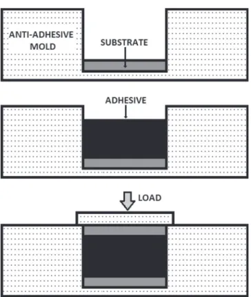
Adhesively bonded joints were prepared by sandwiching a layer of adhesive between two rectangular aluminum foil strips in a poly(tetrafluoroethylene) (PTFE) mold (Fig. 1). Various assem-blies' thicknesses were prepared varying the mold depth. Three assembly configurations were tested and designated by the adhesive thickness of adhesive bond line: 600 mm, 260 mm and 100 mm. A load was applied during 24 h, as recommended by the adhesive manufacturer.
To study mechanical properties of adhesive in a bulk config-uration, films of 1.2 mm in thickness were made by casting onto a PTFE mold.
2.3. Dynamic mechanical experiments
The dynamic mechanical analyses (DMA) were performed on a Rheometrics Scientific ARES of TA Instruments. Tests were carried out in the torsional rectangular mode over the linear elasticity range determined in the first part of this work. Samples were tested by applying a sinusoidal deformation at one end and measuring the resultant sinusoidal torque at the other end. This technique allows us to access the shear complex modulus Gn
ðω; TÞ ¼ G′ðω; TÞ þ iG″ðω; TÞ ð1Þ where G′ is the dynamic storage modulus, G″ is the dynamic loss modulus and tan δ¼ G″/G′ is the loss factor.
In the case of the dynamic mechanical test upon temperature ramp, the isochronous evolution (ω¼ω0) of these values is
recorded as a function of temperature (heating rate: 3 1C/min; ranging from −130 to 150 1C).
Then, G′ varies from the glassy value Ggtill the rubbery value Gr
while G″ passes through a maximum for a temperature TmaxG″
defined by
ω0τðTmaxG″ Þ ¼ 1 ð2Þ
where τ is the anelastic relaxation time.
The temperature variation of tan δ is also a bell shaped curve with a maximum at Tmax
tan δdefined by[30] ω0τðTmaxtan δÞ ¼ ffiffiffiffiffiffiffiffiffiffiffiffiffi Gr=Gg q ð3Þ
3. Results and discussion 3.1. Preliminary experiments
Fig. 2shows the storage modulus G′ as a function of the angular frequency for the three kinds of tested configuration. Measure-ments have been achieved at room temperature. All the values are not influenced by the frequency rate; the adhesive G′ increase (≈0.2 GPa) is not significant compared to the high aluminum modulus (≈30 GPa). Adhesive is tested as a bulk material. The value of the storage modulus is about 1 GPa. It is consistent with values frequently measured for thermoset polymer. Alumi-num foil is also tested as a bulk material. Its modulus is in agreement with shear modulus of aluminum, i.e. 30 GPa [31]. Adhesively bonded joint has an intermediate value of modulus situated between those of its constitutive elements.
The maximal strain amplitude used in DMA experiments has to be well within the linear viscoelasticity range for all the investi-gated samples. Fig. 3 illustrates the test made to check this hypothesis. It represents the torque measured for each sample as a function of strain. Measurements have been achieved using an angular frequency of 1 rad s−1.
Adhesive and assembly stay in their linear viscoelasticity range whatever the strain rate because the torque is linearly dependent on strain. Aluminum tested as a bulk material is not in its linear range for strain rates higher than 2.10−2%.
In order to stay within the linear viscoelastic range and to keep a response with enough intensity a 10–2% strain rate and a 1 rad s−1
angular frequency have been chosen for this study. 3.2. Intrinsic behavior of aluminum
Aluminum foils have been selected in order to be as thin as possible. The aim was to minimize influence of substrates on adhesive signal. Foils are hardly laminated to obtain a 100 mm thickness. They are then annealed to decrease residual stresses. They have been tested as a bulk material to check the temperature stability of the microstructure. The real part of the modulus, G′(T), and the imaginary part G″(T) are reported inFig. 4.
The storage modulus remains constant (about 30 GPa) between −130 1C and +150 1C. On the contrary, the loss modulus increases with temperature:
%
G″ does not present any significant evolution for temperature lower than 20 1C. Values of G″ are of the order of magnitude ofnoise. Torque values are at the detection limit of the transducer. Aluminum is a pure elastic material and there is no energy dissipation.
%
For temperature higher than 20 1C, aluminum has a viscoelasticbehavior. It was already highlighted for pure aluminum[32,33] or aluminum alloys [34,35]. This phenomenon has been assigned to grain boundary dislocations involving a damping effect.
Aluminum foils have a stable elastic modulus but it cannot strictly be consider as an elastic material as expected. There is a loss part in the complex modulus when the temperature is raised above 20 1C.
3.3. Bulk epoxy adhesive
Bulk epoxy adhesive has been analyzed and results are reported inFig. 5. It shows the real part of the modulus, G′, the imaginary part G″ and the loss factor tan δ versus temperature.
The glassy plateau (Gg¼ 2 GPa) and the rubbery plateau
(Gr¼ 1.6.10–2GPa) are identified on the G′ curve. The G′ viscoelastic
step is about two decades (1 GPa at 20 1C and 1.6.10–2GPa at
100 1C) as frequently observed for polymeric systems. This transi-tion called α is identified as the anelastic relaxatransi-tion associated with the glass transition of the adhesive.
The molecular origin of relaxations exhibited on G″ and tan δ curves has already been discussed in previous works [36,37]. Fig. 2. Shear storage modulus as a function of frequency for the aluminum foil,
bulk adhesive and bonded assembly (adhesive thickness: 600 mm).
Fig. 3. Measured torque as a function of strain rate for the aluminum foil, bulk adhesive and bonded assembly (600 mm adhesive thickness).
Fig. 4. Shear storage and loss moduli G′ (%), G″ (○) versus temperature for aluminum foil.
Fig. 5. Shear storage G′ (%), loss G″ (○) moduli and loss factor versus temperature for the adhesive in the bulk configuration.
The β, αPBdand ω relaxations are characterized by the maximum of
the tan δ peak associated with each relaxation. For these relaxa-tions, the maximum of tan δ peaks perfectly match with the maximum of G″ peaks. For the α relaxation, both values of maximum will be noticed. The value presented is an average of data on five samples.
%
The β peak reaches a maximum at −8471 1C. It is associatedwith the mobility of the O–CH2–CHOH–CH2
hydroxypropy-lether units and/or phenyl ring flips[38–41].
%
The αPBdpeak at −5473 7C is associated with the anelasticmanifestation of the glass transition of the polybutadiene phase dispersed in the epoxy network. It is an amine termi-nated butadiene–acrylonitrile copolymer.
%
The ω peak reaches a maximum at 673 1C. This relaxation isassociated with heterogeneities in the adhesive network
[37,42,43].
%
The α peak is associated with the anelastic manifestation of the epoxy glass transition. The maximum of tan δ is at 7071 1C whereas the one of G″ is at 5571 1C.3.4. Bulk/assembly comparison 3.4.1. Viscoelastic storage
The adhesive dynamic mechanical response is studied depend-ing on the test configuration.
Fig. 6 shows the storage modulus versus temperature of adhesive tested as a bulk material and the equivalent storage modulus of adhesively bonded joints with various thicknesses.
The glassy and the rubbery plateaus are determined for both configurations. The bonded assembly has a viscoelastic behavior like a polymeric material. The assembly equivalent modulus values are governed by both aluminum foils modulus and bulk adhesive modulus: assemblies have intermediate properties between the two constitutive materials. The assembly glassy plateau (20 GPa) is less temperature dependent than the bulk adhesive one. The adhesive is rigidified and stabilized by the presence of the two aluminum foils. The equivalent G′ values are influenced by the adhesive thickness: G′ increases for assemblies with a thin adhesive joint.
The evolution of Gg(measured at 10 1C) and Gr(measured at
100 1C) is plotted inFig. 7as a function of the adhesive volume
fraction in the assembly (fadh). The stiffening effect by aluminum
foils (increase of both G′ values) is enhanced when the adhesive fraction decreases. InFig. 6, the decrease in G′ from 40 1C to 90 1C is associated with the anelastic manifestation of the main glass transition. It is only due to the viscoelasticity of the adhesive in the assembly configuration. The Gg–Gr step (Fig. 7) is independent
from the adhesive volume fraction: in other words, the thickness of the joint does not influence the intrinsic viscoelastic response of adhesive. The G′ variations on the glassy and rubbery plateaus are only due to the influence of adhesive volume fraction (low modulus) compared to aluminum volume fraction (high modulus).
3.4.2. Anelastic energy dissipation
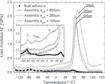
In order to compare relaxation amplitudes and temperatures, the loss part of the modulus (G″) and the loss factor (tan δ) have been plotted as a function of adhesive thickness, inFigs. 8and9
respectively. The relaxation modes have been identified in the figures. The four relaxations identified for the adhesive in a bulk configuration remain visible in the case of 600 mm and 260 mm assemblies. For the 100 mm assembly, the noise is too important due to the low adhesive fraction that prevents significant observations.
Fig. 6. Storage shear modulus G′ versus temperature for bulk adhesive and assembly of various thicknesses.
Fig. 7. Storage modulus G′ as a function of volume fraction of adhesive in bonded assemblies.
The equivalent loss modulus of assemblies G″ (Fig. 8) is higher than for the bulk adhesive. Moreover, G″ decreases with the thickness of assembly and the volume fraction of adhesive that dissipates mechanical energy. Contrarily, the loss factor of assem-blies (Fig. 9) is lower than for the bulk adhesive. Values of G″ are of the same order of magnitude for both configurations (≈0.1 GPa) whereas G′ is two decades higher in the case of assemblies (Fig. 6). Then, as expected, tan δ of assemblies is lower than for the bulk adhesive.
Energy dissipated by aluminum is negligible compared to adhesive. Frictional energy dissipation at the bonded interface between adhesive and substrate is considered as negligible too. Consequently, aluminum foils transmit to polymer the whole energy due to torsional strain. The stress generated in adhesive layer is locally raised by the presence of the rigid substrate. When approaching the glass transition, polymeric sequences become mobile and dissipate this anelastic energy. This phenomenon can explain that the loss modulus of assembly is higher than for bulk adhesive.
Such experimental evidence has been previously reported for sandwich structures or constrained viscoelastic layer damping[44].
Areas under the curves cannot be directly compared because the continuum of G″ signals are dependent on configuration. The amplitude of relaxation peaks is then defined by the difference of its maximum and the continuum. Amplitudes and widths of the relaxation peaks are not dependent upon the configuration except for the α-peak. In the case of bulk adhesive, the G″ α peak has the same height as the β peak (Fig. 5). The ratio of amplitude of α and β peaks is about 1. In the case of assemblies, this ratio is 40 whereas the β peak amplitude does not change. In other words, the energy dissipated at the α relaxation is higher when the adhesive is solicited in an assembly configuration due to the rubbery state of adhesive. Accordingly, when adhesive is in the vitreous state, i.e. in the temperature range of the β relaxation, the stress generated by aluminum foils is analogous with the one transmitted by the vitreous. Energy losses during this relaxation are the same, whatever the configuration tested.
3.4.3. Relaxation modes
The β peak reaches its maximum at −8071 1C whatever the adhesive thickness (the signal of 100 mm assemblies is not suffi-cient to determine the β peak temperature). It is 4 1C higher than the β peak of bulk adhesive. The area under the G″ curve is also independent from the configuration.
The maximum of αPBd peak is at −5072 1C. This peak is not
influenced by the presence of the substrate.
The ω mode is detectable as a shoulder of the α peak. Considering the α peak, G″ reaches a maximum at TmaxG″ ¼ 55 7 1 1C for the bulk adhesive; the G″ peak is situated at TmaxG″ ¼ 63 7 1 1C for 600 mm and 260 mm assemblies. For the 100 mm thick adhesive, this maximum is shifted to higher temperature (TmaxG″ ¼ 69 7 1 1C) with a broadening on the high temperature side. Contrarily, the temperature of the tan δ max-imum is analogous for all configurations and morphologies (Tmax
G″ ¼ 707 1 1C). This apparent discrepancy is discussed from
Eq.(3)where the temperature dependence of the relaxation time is given by
τ¼ τ0expðΔH=RTÞ ð4Þ
where τ0 is the pre-exponential factor, ΔH is the activation
enthalpy, and R is the perfect gas constant.
Then, the temperature shift is given by the following equation: Tmaxtan δ−TmaxG″ ¼ ðRTmaxtan δTmaxG″ =ΔHÞln
ffiffiffiffiffiffiffiffiffiffiffiffiffi Gg=Gr
q # $
ð5Þ Taking into account the ΔH value of the α relaxation mode (≈210 kJ mol−1), we obtain a lag that explains the recorded data.
Indeed, the ratio Gg= Gr is higher in the case of bulk adhesive
(Fig. 6) and it is quite constant whatever the assembly thickness. As a consequence, even if TmaxG″ is lower for bulk adhesive, values of Tmax
tan δ are comparably independent from configurations and
morphologies.
The anelastic manifestation of glass transition can be defined by the temperature of the maximum loss modulus, TmaxG″ [45]. In the study of bulk adhesive, Tmax
G″ perfectly matches with
the calorimetric glass transition temperature measured by differ-ential scanning calorimetry[46]. Moreover, the difference in the temperature of inflection point on G′ curves for both configura-tions corresponds to TmaxG″ (for example, about 8 1C for a 600 mm assembly).
Using this definition, the epoxy network exhibits a higher temperature of mechanical manifestation of the glass transition, Tα, in an adhesively bonded joint compared to bulk configuration. This result is in agreement with the slight increase of the β peak maximum temperature in the 260 mm and 600 mm assembly configuration. Note that the temperature of the β peak of 100 mm assemblies cannot be discussed. The presence of aluminum substrates decreases the mobility in the network. In the vicinity of metallic substrates, the epoxy network is modified [25,47,48] due to specific interactions between adhesive components and aluminum. They lead to an increase of the crosslinks density. This hypothesis is confirmed by the larger distribution of the α relaxa-tion in high temperature region for the 100 mm assembly: the fraction of polymeric sequences influenced by aluminum substrates increases.
4. Conclusion
A new configuration for dynamic mechanical analysis, in the torsional mode, has been developed and tested in order to study the mechanical behavior of an epoxy adhesive in a bonded assembly configuration i.e. in functional conditions. The anelastic behavior of these bonded joints, mainly governed by the visco-elasticity of adhesive, has been compared with the one of bulk adhesive. The mechanical response of the adhesive in an assembly configuration is different from the one of bulk adhesive. Indeed, in such geometry, elastic aluminum substrates transmit a higher torsional solicitation to the sandwich configuration. The influence of adhesive thickness on the equivalent storage modulus is Fig. 9. Loss factor tan δ versus temperature for adhesive and assembly of various
explained by the sandwich geometry and the adhesive volume fraction.
For the α relaxation of assemblies, the equivalent loss modulus is 40 times higher than for bulk adhesive. The shear strain in the adhesive layer is considerably increased, since mechanical proper-ties of the rubbery adhesive and adherent become very different. The analysis of the temperature dependence of the loss modulus provides interesting information on the polymeric network of the adhesive. Adhesive in bonded joint presents a difference in molecular mobility compared to the same adhesive tested as a bulk material. The influence of aluminum substrates is evidenced: the epoxy network should be modified due to the presence of aluminum, during the curing reaction.
The main advantage of the sandwich geometry is to offer a configuration that subjects the adhesive/adherent interface to a shear strain, in functional conditions. Then, the dissipation of anelastic energy may be analyzed in great details.
References
[1]Murayama T. Dynamic mechanical analysis of polymeric material. Elsevier Scientific Publishing Company; 1–231.
[2]Halary JL. Structure–property relationships in epoxy-amine networks of well-controlled architecture. High Perform Polym 2000;12:141–53.
[3]Lonjon A, Demont P, Dantras E, Lacabanne C. Mechanical improvement of P(VDF-TrFE)/nickel nanowires conductive nanocomposites: influence of particles aspect ratio. J Non-Cryst Solids 2012;358:236–40.
[4]Ivanova KI, Pethrick RA, Affrossman S. Investigation of hydrothermal ageing of a filled rubber toughened epoxy resin using dynamic mechanical thermal analysis and dielectric spectroscopy. Polymer 2000;41:6787–96.
[5]Lacoste-Ferre MH, Demont P, Dandurand J, Dantras E, Blandin M, Lacabanne C. Thermo-mechanical analysis of dental silicone polymers. J Mater Sci 2006;41:7611–6.
[6]Takemura A, Tomita BI, Mizumachi H. Dynamic mechanical properties and adhesive strengths of epoxy resins modified with liquid rubber:I—Modifica-tion with ATBN. J Appl Polym Sci 1985;30:4031–43.
[7]Li G, Lee-Sullivan P, Thring RW. Determination of activation energy for glass transition of an epoxy adhesive using dynamic mechanical analysis. J Therm Anal Calorim 2000;60:377–90.
[8]Cook RW, Tod DA. A study of the cure of adhesives using dynamic mechanical analysis. Int J Adhes Adhes 1993;13:157–62.
[9]Wang JW, Laborie MPG, Wolcott MP. Kinetic analysis of phenol–formaldehyde bonded wood joints with dynamical mechanical analysis. Thermochim Acta 2009;491:58–62.
[10]Tsang CF, Hui HK. An alternative method to the curing study of polymeric die attach adhesives using dynamic mechanical analysis. Thermochim Acta 2001;367:169–75.
[11]Li C, Dickie RA, Morman KN. Dynamic mechanical response of adhesively bonded beams: effect of environmental exposure and interfacial zone proper-ties. Polym Eng Sci 1990;30:249–55.
[12]Brinson HF, Dickie RA, Debolt MA. Measurement of adhesive bond properties including damage by dynamic mechanical thermal analysis of a beam speci-men. J Adhes 1995;55:17–30.
[13]Phung LH, Kleinert H, Jansen I, Hassler R, Jahne E. Improvement in strength of the aluminium/epoxy bonding joint by modification of the interphase. Macromol Symp 2004;210:349–58.
[14]Jansen I, Simon F, Hassler R, Kleinert H. Aluminium preatreatment and the properties of adhesively bonded joints. Macromol Symp 2001;164:465–78. [15]Budzik MK, Jumel J, Shanahan MER. An in situ technique for the assessment of
adhesive properties of a joint under load. Int J Fract 2011;171:111–24. [16]Kinloch AJ, Little MSG, Watts JF. The role of the interphase in the
environ-mental failure of adhesive joints. Acta Mater 2000;48:4543–53.
[17]Dolev G, Ishai O. Mechanical characterization of adhesivelayer in-situ and as bulk material. J Adhes 1981;12:283–94.
[18]Lilleheden L. Mechanical properties of adhesives in-situ and in bulk. Int J Adhes Adhes 1994;14:31–7.
[19]Morman KN, Li C, Zhang F, Dickie RA. Determination of the complex shear modulus of structural adhesives using a doubly clamped sandwich beam. Exp Mech 1992;32:124–31.
[20] Burst N, Adams DO, Gascoigne HE. Investigating the thin-film versus bulk material properties of structural adhesives. J Adhes 2011;87:72–92. [21]Jeandrau JP. Intrinsic mechanical characterization of structural adhesives. Int J
Adhes Adhes 1986;6:229–31.
[22] Peretz D. Shear stress–strain characteristics of adhesive layers. J Adhes 1978;9:115–22.
[23] Chai H. Deformation and failure of adhesive bonds under shear loading. J Mater Sci 1993;28:4944–56.
[24] Brinson HF. The viscoelastic constitutive modelling of adhesives. Composites 1982;13:377–82.
[25] Roche AA, Bouchet J, Bentadjine S. Formation of epoxy-diamine/metal inter-phases. Int J Adhes Adhes 2002;22:431–41.
[26] Aufray M, Roche AA. Epoxy-amine/metal interphases: influences from sharp needle-like crystal formation. Int J Adhes Adhes 2007;27:387–93.
[27] Meiser A, Kübel C, Schäfer H, Possart W. Electron microscopic studies on the diffusion of metal ions in epoxy–metal interphases. Int J Adhes Adhes 2010;30:170–7.
[28] Montois P, Nassiet V, Petit JA, Adrian D. Viscosity effect on epoxy-diamine/ metal interphases—part II: mechanical resistance and durability. Int J Adhes Adhes 2007;27:145–55.
[29] Causse N. Analyse des relaxations enthalpiques, mécaniques et diélectriques pour l'étude du vieillissement d'assemblages collés structuraux. PhD thesis. Université Paul Sabatier, Toulouse; 2012.
[30] McCrum NG, Read BE, Williams G. Anelastic and dïelectric effects in polymeric solids. John Wiley; 102–40.
[31]Mondolfo LF. Aluminum alloys: structure and properties. Butterworths; 68–95.
[32] Gallego I, Nó ML, San Juan J. Analysis of the internal friction spectra of high purity aluminium at medium temperatures. J Alloys Compd 2000;310:119–23. [33] Kê TI-S. Experimental evidence of the viscous behavior of grain boundaries in
metals. Phys Rev 1947;71:533–46.
[34] Aguiar Rodriguez A. Characterization of the viscoelastic properties of aero-space aluminium alloys 2024 T3 and 7075 T6, Escola Politècnica Superior de Castelldefels (EPSC). Castelldefels—Barcelona: Universitat Politècnica de Catalunya; 2009.
[35] Carreño-Morelli E, Ghilarducci AA, Urreta SE. High-temperature damping in Al–Mg–Si industrial alloys. Phys. Status Solidi A 1996;158:449–62.
[36] Chevalier M. Vieillissement hygrothermique d'assemblages structuraux poly-epoxy: analyse de la mobilité moléculaire par spectroscopie diélectrique dynamique. PhD Thesis. Université Paul Sabatier, Toulouse; 2008.
[37]Chevalier M, Dantras E, Tonon C, Guigue P, Lacabanne C, Puig C, et al. Correlation between sub-Tg relaxation processes and mechanical behavior for different hydrothermal ageing conditions in epoxy assemblies. J Appl Polym Sci 2010;115:1208–14.
[38] Heux L, Halary JL, Lauprêtre F, Monnerie L. Dynamic mechanical and 13C n.m.r. investigations of molecular motions involved in the β relaxation of epoxy networks based on DGEBA and aliphatic amines. Polymer 1997;38:1767–78. [39] Boye J, Demont P, Lacabanne C. Secondary retardation modes in diglycidyl
ether of bisphenol A—diamino diphenyl methane networks. J Polym Sci. Part B: Polym Phys 1994;32:1359–69.
[40] Williams JG. The beta relaxation in epoxy resin-based networks. J Appl. Polym. Sci 1979;23:3433–44.
[41]Dammont FR, Kwei TK. Dynamic mechanical properties of aromatic, aliphatic, and partially fluorinated epoxy resins. J Polym Sci A2 1967;5:761–9. [42] Gupta VB, Drzal LT, Lee CYC, Rich MJ. The temperature-dependence of some
mechanical properties of a cured epoxy resin system. Polym Eng Sci 1985;25:812–23.
[43] Foreman J, Porter D, Behzadi S, Travis K, Jones F. Thermodynamic and mechanical properties of amine-cured epoxy resins using group interaction modelling. J Mater Sci 2006;41:6631–8.
[44]Kerwin EM. Damping of flexural waves by a constrained viscoelastic layer. J Acoust Soc Am 1959;31:952–62.
[45] Rieger J. The glass transition temperature Tgof polymers—comparison of the values from differential thermal analysis (DTA, DSC) and dynamic mechanical measurements (torsion pendulum). Polym Test 2001;20:199–204.
[46] Causse N, Dantras E, Tonon C, Chevalier M, Guigue P, Combes H, Lacananne C. Environmental ageing of aerospace epoxy adhesive in bonded assembly configuration. J Therm Anal Calorim 2013 DOI: 10.1007/s10973-013-3009-3, in press.
[47]Bockenheimer C, Valeske B, Possart W. Network structure in epoxy aluminium bonds after mechanical treatment. Int J Adhes Adhes 2002;22:349–56. [48] Possart W, Krüger JK, Wehlack C, Müller U, Petersen C, Bactavatchalou R,
Meiser A. Formation and structure of epoxy network interphases at the contact to native metal surfaces. C R Chim 2006;9:60–79.