Publisher’s version / Version de l'éditeur:
Vous avez des questions? Nous pouvons vous aider. Pour communiquer directement avec un auteur, consultez la première page de la revue dans laquelle son article a été publié afin de trouver ses coordonnées. Si vous n’arrivez pas à les repérer, communiquez avec nous à [email protected].
Questions? Contact the NRC Publications Archive team at
[email protected]. If you wish to email the authors directly, please see the first page of the publication for their contact information.
https://publications-cnrc.canada.ca/fra/droits
L’accès à ce site Web et l’utilisation de son contenu sont assujettis aux conditions présentées dans le site
LISEZ CES CONDITIONS ATTENTIVEMENT AVANT D’UTILISER CE SITE WEB.
Canadian Building Digest, 1981-06-01
READ THESE TERMS AND CONDITIONS CAREFULLY BEFORE USING THIS WEBSITE.
https://nrc-publications.canada.ca/eng/copyright
NRC Publications Archive Record / Notice des Archives des publications du CNRC :
https://nrc-publications.canada.ca/eng/view/object/?id=e651868c-c5a8-4ac5-871d-af90d57c825b
https://publications-cnrc.canada.ca/fra/voir/objet/?id=e651868c-c5a8-4ac5-871d-af90d57c825b
NRC Publications Archive
Archives des publications du CNRC
For the publisher’s version, please access the DOI link below./ Pour consulter la version de l’éditeur, utilisez le lien DOI ci-dessous.
https://doi.org/10.4224/40000695
Access and use of this website and the material on it are subject to the Terms and Conditions set forth at
Spread of fire between buildings
Canadian Building Digest
Division of Building Research, National Research Council Canada
CBD-216
Spread of Fire Between Buildings
Please note
This publication is a part of a discontinued series and is archived here as an historical reference. Readers should consult design and regulatory experts for guidance on the applicability of the information to current construction practice.
Originally published June 1981. J.H. McGuire, G. Williams-Leir
Until quite recently, fire could, and sometimes did, threaten the total destruction of the whole or a large part of a city or community. Once a fire had reached very large proportions involving say, a whole city block, the level of radiation issuing from it was so great that materials 100 m (300 ft) away could be ignited. At this stage, containment of the fire might no longer be possible.
The most important reason why such catastrophes are now less frequent is probably the general adoption of the rule that any fire should be contained within the building of origin by the use of fire-resistant building components, by spatial separation, and by firefighting. Design recommendations concerning spatial separation generally involve the assumption that
firefighting will reduce the risk of ignition of adjacent buildings, both by wetting them down and by playing water on the primary fire, and thus reducing the fire's level of thermal radiation. Fire-resistant construction is sometimes adequate, but often firefighting is essential if a fire is to be contained by the construction.
Containment and Fire Resistance
The object of making construction components fire resistant is, firstly, to ensure that they will continue to support imposed loads during a fire, and secondly, in the case of walls and floors, to hinder the propagation of fire to adjacent compartments or buildings either by the
conduction of heat or by the flow of hot gases. The degree of fire resistance necessary for any component to achieve this depends on the expected severity of the fire which, in turn, depends on several factors, e.g., ventilation, fire load (quantity of combustibles), insulating properties of wall, ceiling, and floor, and fuel surface area. Rather than evaluating fire resistance
requirements on a technical basis, designers commonly rely on model building regulations such as the National Building Code, which specifies fire-resistance requirements in terms of the occupancy. This does not take account of all relevant factors, however, and designers should increase fire-resistance requirements if the hazards of a particular building are greater than those typical of the occupancy, e.g., if the building contained more combustibles, or had more flammable interior finishes, or fewer windows.
Fire Walls
A table of fire resistances of walls, based on test results, is included in the Supplement to the National Building Code.1These tables assume that once the expected fire duration is reached,
firefighters will have access to the fire; however, where this may not be true, as in high-rise buildings, other measures are necessary, e.g., sprinklers or greater thicknesses of building components.
Why Fire Walls May Fail
Separation walls very often include unintended paths by which a fire can circumvent them. A typical fault found in row housing is that combustible eaves are continuous, permitting fire to propagate past a fire partition or wall. Similar but worse conditions often prevail in mansard roofs, where continuous combustible roofing supports are erected. Sometimes the fire partition does not even extend out to the mansard roof; it should project through the roof.
Supporting a combustible member by insetting it into a fire partition is another source of the problem, as this arrangement reduces the fire resistance of the nearby partition. For hazard to exist, there must be combustible material on the far side of the partition. Fire propagation by this mechanism is rarely found, therefore, except where combustible members are inset into a wall from both sides opposite one another.
Services between two buildings often create hazard where ducts, pipes or cables penetrate a fire partition. Although, especially in the case of metal ducts or pipes, conduction can
theoretically give rise to fire propagation, the more common cause is failure to close completely the openings around the services. Virtually any cable can safely penetrate a fire-resistant wall, provided the opening through which it passes is carefully sealed with a suitable
high-temperature-resistant material. plastic pipes, however, can propagate fire when positive pressure differentials prevail and the pipe communicates with a vented rather than a closed system.
Unless the opening is relatively large, the hazard just discussed results from the flow of hot gases (and flames) from the fire region, and thus it exists only where the pressure differential across the fire partition is positive (higher on the fire side). The sources of such differentials should, therefore, be considered; they include wind and stack effect and expansion due to temperature rise.
During a fire, temperatures are likely to fluctuate and, during each upswing, a small positive pressure can develop. Magnitudes will depend on rate of temperature rise and the ratio of the total volume of the enclosure to the leakage area of its bounding surfaces. Values will rarely exceed 25 Pa (3 mm water gauge). The Influence of wind is too obvious to need detailed explanation: pressure differential magnitudes will rarely exceed maximum values associated with expansion.
Stack Effect Is Not The Problem
Stack, or chimney, effect is a major factor in the migration of smoke and in the transmission of fire through openings, within buildings. However, the subject of this Digest is the spread of fire between buildings, and in this context, where the dividing partition is usually a wall (i.e., is vertical), stack effect will be of much less importance. Across a wall dividing two buildings heated equally, only minimal pressure differentials would result from building heating, because the effect will be much the same on either side.
Fire Spread Between Spatially Separated Buildings
The spread of fire from one building to another separated from it by a vacant space may result from one or more of the following: flying brands, convective heat transfer, and radiative heat transfer.
Flying brands. -- These may initiate secondary fire at substantial distances from the primary fire, e.g., 0.5 km. It is unlikely, however, that exterior claddings (other than cedar shingles and shakes) or roofing materials will be directly ignited even by large brands. So far as the exposed building is concerned, the hazard is associated more with extraneous kindling materials, such as birds' nests, and with half-enclosed regions likely to favour ignition, e.g., wood siding behind a wooden shutter.
Convective heat transfer. -- This will cause ignition only if the temperature of the gas stream is several hundred degrees Celsius. Such high temperatures are found in or very near the flames issuing from burning buildings, e.g., where an adjacent building is ignited by flames above a
burning building after its roof has fallen in. Special protection should thus be given to windows of any building that overlooks the non-fire-resistive roof of an adjacent building.
Thermal radiation. -- Radiation levels from burning buildings were investigated as part of a program of full-scale burns carried out by DBR in 1958. The main findings were:
the nature of exterior cladding did not noticeably influence radiation levels.
the variation of radiation intensity with distance from the source was consistent with the
assumption that window openings, at temperatures higher than fire temperatures, were the sole source of radiation.
peak radiation levels from buildings with highly flammable linings were twice those from buildings with noncombustible linings.
radiation levels were affected by wind direction; those on the leeward side of a building were generally much greater than those on the windward side.
Using the second result, hypothetical peak radiation levels at window openings on the leeward sides of the buildings were nearly 1600 and 800 kW/m², respectively, for buildings with highly flammable and noncombustible linings. These values are much greater than the maximum level to be expected at window openings, which is about 160 kW/m², because radiation from the flames above windows was treated as emanating from the window openings.
It might be thought that to avoid combustible materials as exterior cladding on a building would minimize risk of ignition by radiation. This proves not to be true, because materials within a building are often as prone to ignition as the exterior cladding. The protection offered by glass windows is destroyed at an early stage because the glass cracks and falls out. That the interior materials are within an enclosure more than compensates for any reduction in exposure to radiation. With only a small opening exposed to radiation, the interior temperature of an enclosure can exceed that of the more exposed surface adjacent to the opening.
The possible radiation levels at the facade of an exposed* building must be kept below a hazardous level (generally taken as 12.5 kW/m²). This is achieved by spatial separation and by minimizing the total area of windows that could emit radiation from a burning building. The relation between the levels of radiation at an exposed building is purely geometrical, but unfortunately it is complicated and not easily evaluated.
If one wishes to have information in simple tabular form relating window openings (in an exposing* building) and suggested spatial separations, it is convenient to adopt the simplifying assumption that the whole facade that includes the relevant window openings is radiating uniformly. Tables can then be prepared that show the relation between dimensions of facade, percentage of window opening in facade, and the distance of spatial separation necessary to limit irradiation to the acceptable level.
The validity of such tables breaks down where the percentage of openings in the (exposing) facade is particularly low. The extreme of the latter condition occurs when the ratio of window openings to facade is less than a certain value (0.07 for normal hazard, 0.035 for high hazard). A table based on the assumption of uniform radiation from the facade would specify that no spatial separation is necessary under these circumstances, and this is untrue.
Accurate spatial separations that take account of this problem are most conveniently
determined with a programmable pocket calculator.2A good approximation can, however, be
obtained from tables, of which the most convenient form is given in the same reference (see also Table 1).
The spatial separations thus arrived at should be regarded as a compromise, because they alone do not provide protection for an indefinite period, but depend on the fact that in the original experiments the peak radiation level was attained only after 16 minutes from ignition, and on the assumption that, before that time, active firefighting would have begun and water applied to cool the exposed surfaces or quench the exposing fire.
These methods relate to facades where all openings are in the same plane. Approximations are required when dealing with more complicated situations.3,4
Figure 1. Example to illustrate terminology.
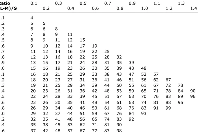
For example, if G = 24 m, S = 16 m, and L = 25 m: [M = 1 m]. (L-M)/G = 1.0
(L-M)/S = 1.5
Enter Table I at the column headed 1.0 and the row 1.5 to find 70, which means that for high hazard occupancy no more than 70% of the facade may be openings. For low hazard this is doubled, meaning no restriction on openings.
Table I. Dimensionless spatial separations. Ratio (L-M)/G Ratio (L-M)/S 0.1 0.2 0.3 0.4 0.5 0.6 0.7 0.8 0.9 1.0 1.1 1.2 1.3 1.4 0.1 4 0.2 5 5 0.3 6 6 8 0.4 7 8 9 11 0.5 8 9 11 12 15 0.6 9 10 12 14 17 19 0.7 11 12 14 16 19 22 25 0.8 12 13 16 18 22 25 28 32 0.9 13 15 17 21 24 28 31 35 39 1.0 15 16 19 23 26 30 35 39 43 48 1.1 16 18 21 25 29 33 38 43 47 52 57 1.2 18 20 23 27 31 36 41 46 51 56 62 67 1.3 19 21 25 29 34 39 44 50 55 61 67 72 78 1.4 20 23 26 31 36 42 48 53 59 65 71 78 84 90 1.5 22 24 28 33 39 45 51 57 63 70 76 83 89 96 1.6 23 26 30 35 41 48 54 61 68 74 81 88 95 1.8 26 29 34 40 46 53 61 68 76 83 91 99 2.0 29 32 37 44 51 59 67 76 84 93 2.2 32 35 41 48 56 65 74 83 92 2.4 35 38 45 53 62 71 81 90 2.6 37 42 48 57 67 77 87 98
2.8 40 45 52 61 72 83 94 3.0 43 48 56 66 77 88 3.5 50 56 65 77 89 4.0 57 64 74 87 4.5 65 72 84 98 5.0 72 80 93 5.5 79 88 6.0 86 95 6.5 93
Given L, the distance from the facade to lot line or centre of street (see Figure 1), subtract M = 3 ft or 1 m. Divide by G, the greater dimension of the facade, for (L-M)/G, and choose the appropriate column of the table. Divide M) by S, the smaller dimension of the facade, for (L-M)/S, and choose the appropriate row of the table. Where row and column meet, find the maximum openings as percentage of facade area. For high hazard occupancies (National Building Code's Groups E and F, Divisions 1 and 2); other occupancies may have twice the opening area.
Conclusions
Fires involving entire towns are less common than in earlier times because of changes in construction methods and materials and in spatial separations between buildings. Fire spread by thermal conduction is now controlled by appropriate construction, which should take account of the severity of the potential fire. Spread of fire by flying brands can be minimized by proper roof construction; convective heat transfer is likely only where windows overlook a roof that is not fire-resisting. The risk of spread by thermal radiation can be limited by sufficient separation and ways of calculating this are available. Giving proper attention to these factors will greatly reduce the possibility of the spread of fire, but an effective firefighting capability is still an essential requirement.
References
1. The Supplement to the National Building Code of Canada, 1980, p. 31-43: Fire Resistance Ratings.
2. Williams, G., Program for pocket calculator to derive spatial separations to deter fire spread, Nat. Res. Council of Canada, Div. Bldg. Res., Ottawa. Computer Program 44, May 1978.
3. Law, Margaret, Fire Note 8, Joint Fire Research Organization, 1966.
4. Law, Margaret, Heat radiation from fires and building separation, Fire Research Tech. Paper No. 5, HMSO, London, 1963.
* When a fire in one building causes the ignition of another, the former is referred to as the 'exposing' building, and the latter as the 'exposed' building.