Publisher’s version / Version de l'éditeur:
Vous avez des questions? Nous pouvons vous aider. Pour communiquer directement avec un auteur, consultez la première page de la revue dans laquelle son article a été publié afin de trouver ses coordonnées. Si vous n’arrivez pas à les repérer, communiquez avec nous à PublicationsArchive-ArchivesPublications@nrc-cnrc.gc.ca.
Questions? Contact the NRC Publications Archive team at
PublicationsArchive-ArchivesPublications@nrc-cnrc.gc.ca. If you wish to email the authors directly, please see the first page of the publication for their contact information.
https://publications-cnrc.canada.ca/fra/droits
L’accès à ce site Web et l’utilisation de son contenu sont assujettis aux conditions présentées dans le site LISEZ CES CONDITIONS ATTENTIVEMENT AVANT D’UTILISER CE SITE WEB.
Internal Report (National Research Council of Canada. Division of Building
Research), 1963-11-01
READ THESE TERMS AND CONDITIONS CAREFULLY BEFORE USING THIS WEBSITE. https://nrc-publications.canada.ca/eng/copyright
NRC Publications Archive Record / Notice des Archives des publications du CNRC :
https://nrc-publications.canada.ca/eng/view/object/?id=39fad3ee-97c3-4412-a390-70a9bd75d52a https://publications-cnrc.canada.ca/fra/voir/objet/?id=39fad3ee-97c3-4412-a390-70a9bd75d52a
NRC Publications Archive
Archives des publications du CNRC
For the publisher’s version, please access the DOI link below./ Pour consulter la version de l’éditeur, utilisez le lien DOI ci-dessous.
https://doi.org/10.4224/20386764
Access and use of this website and the material on it are subject to the Terms and Conditions set forth at
Space between buildings as a means of preventing the spread of fire.
Report A: survey of a fully developed residential area adjacent to
downtown Vancouver
NATIONAL RESEARCH COUNCIL CANADA
DIVISION OF BUILDING RESEARCH
SPACE BETWEEN BUILDINGS AS A MEANS OF PREVENTING THE SPREAD OF FIRE
Report A -- Survey of a fully developed residential area adjacent
to downtown Vancouver by
H. P. Oberlander, W. Gerson and R. D. Goldsworthy School of Architecture, University of British Columbia
Vancouver, B. C.
, ' It
.e«j • "
r
'f7 ::DA Joint Project of the School of Architecture
and the Graduate Program in Community and Regional Planning, University of British Columbia
and the
Division of Building Research, National Research Council
Internal Report No. 280 of the
Division of Building Research
OTTAWA November 1963
I.
The late Professor Fred Lasserre, as Director of the School of Architecture at the University of British Columbia, was one of the original sponsor s of this
research project. His contribution is
remembered appreciatively by all con-nected with this Report.
PREFACE
This report is one of a series of four which are concerned with space between buildings as a m.eans of preventing the spread of fire, which in turn form.s part of a rna in research project "Perform.ance Standards for Space and Site Planning for Residential Developm.ent. "
This project has been undertaken for the Division by the
School of Architecture at the University of British Colum.bia. Two
reports have already been issued: An Annotated Bibliography on
Perform.ance Standards for Space and Site Planning for Residential Developm.ent (NRC 6442) and DBR Internal Report No. 273, "A Study of Pe r fo r mance Standards for Space and Site Planning for Residential
Developm.ent." The latter contains a discus sion of the factors that
determ.ine the spacing of residential buildings. This present series
of four reports deals with one of these factors - - fire. The other
factors J including daylight, noise and privacy will be dealt with in
subsequent reports. When all of these reports are issued, they will
form. a com.plete evaluation of the conditions that m.ust be considered in the planning of residential areas in Canada.
The first two authors of this report are on the staff of the
University of British Co lurnb ia , Professor Oberlander, besides his
duties on the staff of the School of Architecture, is Head of the Graduate Program. in Com.m.unity and Regional. Planning; Professor
Gerson, at the tirne this report was written, was Acting Director of
the School of Architecture. Mr. Goldsworthy, a graduate architect,
was engaged as research assistant to the project. Professor Henry
Elder is the present Head of the School of Architecture; the project was initiated under the direction of his predecessor, the late Professor
Fred Lasserre.
This infor mat ion is being issued in the Divisional series of internal reports so that those responsible for the work can have the benefit of inform.ed com.m.ents prior to publishing in a m.ore form.al
way. Co rnrrie nt s will therefore be welcom.ed and should be sent
either to Professor Oberlander at the University of British Co lurnb ia or to the wr iter at Ottawa.
I
Ottawa
Novem.ber 1963
R. F. Legget
INTRODUCTION TABLE OF CONTENTS
...
Page No. 1 PART 1The Analytic Method
...
3PART 2
Description of the Area .
Factors that Shaped the Area . . • . . . .
Building and zoning bylaws .
Subdivision of land .
Results of these Factors . . . • . . . .
PART 3 Definitions . . . • . . . . Compartment . . . • . . . . Enclosing rectangle . . . • . . . • . . . • . • • . . . . . Opening . Distribution of openings . Plane of reference . . . • . • . • . . • . . . . Separation .
Open and enclosed interior stairs . . . • . . .
Analyses of Typical Spaces . . . • . . . • . . . . .
Comments on Analyses ...' . . • . . . • . . • . . • . . • . . . . .
BIBLIOGRAPHY . . . • . • . . . • . .
APPENDIX A - Remainder of the Analyses
Summary of the Spatial Separations
APPENDIX B - Description of the Buildings in the Study Area
12 13 13 14 15 19 19 19 19 20 20 20 21 21 52 56
SPACE BETWEEN BUILDINGS AS A MEANS OF PREVENTING THE SPREAD OF FIRE
REPORT A Survey of Fully Developed Residential Area
Adjacent to Downtown Vancouver by
H. P. Oberlander, W. Gerson and R. D. Goldsworthy
INTRODUCTION
The volume of post-war housing across Canada has revealed a great number of problems in the use of site planning standards as a
basis for achieving a high quality of residential communities. This
unprecedented volume. coupled with the concentration of new housing in the suburbs of Canadian cities. has made a rational layout of the many hundreds of units in relation to e ach other and to their communal
facilities very difficult. Traditional space and location standards
for large-scale housing have not been able to control resulting
develop-ment adequately. In most instances, it has merely allowed hou s ing to
be built in a mechanically neat .and orderly fashion. More flexible and
imaginative standards of house grouping and layout seem essential if the next flood of housing in Canadian cities is to add more to urban Canada than merely further volume of accommodation.
Throughout the post-war decade Canadian cities and towns became aware of the value of community planning and of their respective responsibilities for controlling the individual's use of his land for the
benefit of the community as a whole. Traditionally, town planning
has been closely linked with rules and regulations laid down in bylaws, uniformly applied throughout the jurisdiction of a given city or town. These rules and regulations, usually contained in a zoning or subdivision control bylaw, restrict the way in which buildings may be sited on their respective lots and the amount of space on that lot that has to remain
open and unobstructed by any construction. These regulations often
include minimum front and rear yard dimensions as well as side yard
limitations and related restrictions as to the height of buildings. It
is usually contended that it is in the community's interest to set certain space standards between and around buildings to achieve safety, minimum
2
-regulations as a rule are expressed in absolute measurements of distance, and result in monotonous and rigid spacing of buildings. This is particularly true of re sidential areas that have been built in large groups of single units; the typical post-war housing sub-division falls into this category.
The main purpose of the research project is to demonstrate that adequate space around and between buildings for functional and aesthetic purposes can be achieved with greater flexibility and without
unduly restricting the siting of residential buildings. Such flexible
standards are usually referred to as performance standards since they determine space between and around buildings by the variety of functions that they are to perform and in relation to the size and
dimension of land and buildings in a given situation. In the post-war
decade, performance standards were used in the siting and building of
industrial and commercial structures. This e xp e-rie n c e demonstrated
that performance standards provide a more flexible framework for the designer of individual buildings or groups of buildings and also enable government agencies to administer regulations effectively.
The present report forms a portion of this research. The
research began with a survey of literature from which an annotated
bibliography was prepared (2). This gave the ゥョゥセゥ。ャ direction to the
work and was used extensively during the following studies. The
factors which determine the spacing of residential buildings were then
investigated (3). The full range of community objectives are fire,
daylight, air, noise, privacy, view, traffic and outdoor space. The general aim of this part of the investigation, now reported, is to study the application of the prevention of fire as a determinant of space between buildings in residential areas and to
develop specific methods for the application of these standards. This
particular field of investigation was chosen because of the critical
nature of fire safety and because information was more readily available
than for some of the other community objectives. The information which
is here discussed is based on fire studies conducted by the Division of Building Research and similar bodies throughout the world.
The first part of this investigation consists of three field surveys of actual residential developments in Metropolitan Vancouver*. The information thus obtained provides the basis for formulating a technique for applying performance standards to the prevention of fire spread from building to building through the flexible use of the space between them (contained in DBR Internal Report No. 283 by H. P. Oberlander and R. S. Ferguson).
* This report (DBR Internal Report No. 280), and DBR Internal Reports
3
-PART 1 THE ANALYTIC METHOD
It is the purpose of this stage to examine current conditions
and standardsj hence the investigation begins with a survey of existing
residential areas of a varied nature in order to obtain as wide a view as possible of the total range of residential development in a typical Canadian metropolitan area.
These surveys consist of field questionnaires and measured
drawings for each building. A summary of this information for all of
the buildings within the area now reported on will be found in Appendix
A. This method yields an adequate explanation of the construction and
geometry of the buildings but does not fully show the relationship of
a building to its neighbours. To demonstrate this a scale model of
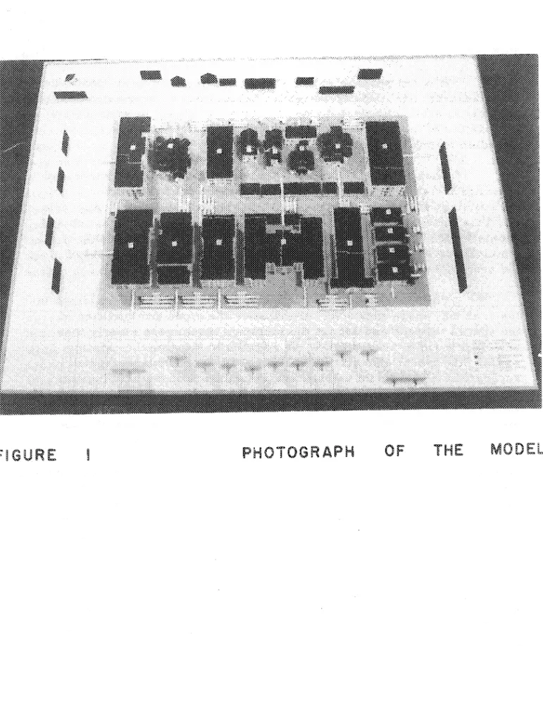
the area was constructed (Figures I, 2 and 3).
The model indicates not only the relationships of buildings in the area but, more important, it indicates the types and qualities of the spaces between and around the buildings much more clearly than
any other form of pr e se ntat ion: In addition to showing the existing
spaces, the model also allowed graphical illustration of the spatial
separations which would be required if the layout of the buildings on
the site were to conform to certain standards other than those which
were in effect at the time of construction. These standards will be
more fully explained in the following pages and the analyses of some
typical spaces will be found in Part 3 of this report. The required
separations between buiIding s are represented on the model by strips of
cardboard and are placed, in conjunction with similar strips representing the actual separations, adjacent to the spaces between the buildings.
This allows comparisons to be made at a glance of the spatial
separations required by the different standards. The result will be
seen in the photographs of the model (Figures I, 2 and 3).
Any study of existing conditions is incomplete without an
investigation of the forces which shaped them. Among others, great
influence is exercised by the historic sequence of building and zoning bylaws through which the public controls the siting and the form of
individual buildings for purposes of public safety. Since this survey is
restricted to the control of conflagrations by space separations, the extent to which past regulations are based on considerations of fire
safety will become evident. This will allow demonstration of the effect
セ 5 -セセセセセセMMMMMMMMMMG[MG[[ZZGZャ I I
FiGURE
FIGURE
6
-Analyses of existing spaces consist of checking the spaces
against three standards: Table 3.2.2. A. of the 1960 National Building
Code of Canada (6), Table VI contained in the Division of Building
Research Internal Report No. 187 by J. H. McGuire (5), and a
conversion of Table VI. For convenience, these shall be designated
Tables 1, 2 and 3 respectively (see pages 9, 10 and 11). In one of
the examples contained in Part 3 of this report (p. 35) two tables from "Fire
and Space Separation" by Mr. G. J. Langdon Thomas (11) have been
used.
The reasons for choosing Table 1 were twofold. First, it
showed how the regulations concerning the use of s patial separations
have changed from the time when the buildings in the study area were
originally designed and constructed. Also, the project could be used
as a testing ground for the use of the table, as a basis for comment On its workability and discus sion of its advantages and limitations
under a variety of conditions. These comments will be found in Part 3
of this report.
Table 2 was used because it formed the basis for Table 1. It was therefore interesting to compare the results of the se two stan-dards in order to assess the agreement between them and to comment on the workability of the two different forms of pre sentation.
Tables 1 and 2, however, give the required spatial separations
in terms of distance from the building face to the lot line. This was done
to simplify the application and to avoid administrative difficulties. In
order to increase the flexibility of the standards and, incidentally, to make them more consistent with the results of original research conduc-ted by the Division of Building Research, Table 2 was converconduc-ted to give
the separations in terms of space from building to building. This also
overcame some inconsistencies inherent in the previous approach. Comments on these points will be found in the analyses of the typical
spaces. The conversion is included in this report as Table 3.
The remaining tables are the result of British research into the problem of controlling the spread of fire by means of spatial separations
between buildings. These tables were used in one of the examples (p. 35)
contained in Part 3 to allow a comparison between them and their
Canadian counterparts. This comparison was especially important
since some of the analytic techniques advocated by Mr. Thomas in his report (11) have been used.
7
-It should be mentioned that the analyses are based on two
assumptions: that all of the buildings studied have a fire load of 10
pounds per square foot and that the spread of fire takes place primarily by radiative heat transfer.
The fire load concept has been defined as follows:
"If the .. , amount of the combustible contents of a building
are divided by the floor area, a figure is obtained which allows comparison between different buildings, or different
parts of the same building. Fire load is thus determined
in B. Th. U' s per sq. ft. by the formula: cal. value of contents
in B. Th. U' s per lb. x
weight of contents in lb.
Floor area in sq. ft.
"Because most buildings are built for a specific occupancy, it is possible to predetermine fairly accurately their
maximum fire loads infulluse." (1, p.47, 48).
From discussions with officials of the Division of Building Research, it was found that the value of 10 pounds per square foot is
the one on which the table 3.2 ..2. A. of separation in the National
Building Code was based. This is also approximately the same as the
values assumed in the St. Lawrence Burns experiments which were conducted by the Division in 1958 (10).
As for the assumption that the spread of fire from building to building takes place by radiation, it is stated in "Spatial Separation of Buildings" (5, p . l ) that:
"The spread of fire between two buildings may result from:
1. Flying brands
2. Convective heat transfer and/or
3. Radiative heat transfer.
"Flying brands may initiate secondary fires at substantial distances from the primary fire, e. g. a quarter of a mile, and thus it is not practical to consider spatial separation between buildings as a means of combatting this hazard. Fortunately other means are available.
"Convective heat transfer will only cause ignition if the temperature of the gas stream is several hundred degrees
8
-Centigrade. Such high gas temperatures are only to
be found in or very near to the flames emanating from the windows of burning buildings.
"Since ignition by radiation from a burning building can occur at distances greater than those to which the flames generally extend it follows that radiative heat transfer is the factor of primary importance in
producing spread of fire across a space separation between buildings . . . . "
9
-TABLE 1
SEPARATION FROM LOT LINE
LIMITING DISTANCE, ft
Area of EllpOse<! lIaUo 4 6 10 15 20 30 50 70 100 140 Building Face.sqft L/Hor H/L- Permtssfble Area of Unprotected Opening.
In Exposed Building Face, per cent
len than 3:1 5 7 15 32 57 100 100 100 100 100
Ie.. than 300 3:1 to 10:1 6 9 18 34 63 100 100 100 100 100
over 1011 9 13 25 44 68 100 100 100 100 100
300 and over len than 3:1 5 612 23 41 61S 100 100 100 100 but less than 400 3.1over to 10:110,1 68 118 15 27 4520 35 55 100 100 100 100 10080 100 100 100 100
400 and over less than'3,1 4 6 11 21 34 73 100 100 100 100 but len than 500 3:1over to 10:110:1 57 10 18 31 477 13 23 37 75 100 100 100 10087 100 100 100 100
500 and over leu than 3:1 4 6 10 18 19 60 100 100 100 100
3:1 to 10:1 5 7 11 19 32 70 100 100 100 100
but less than 600
over 10:I 7 10 17 28 41 80 100 100 100 100
600 and over less than 3:I 4 5 8 15 23 50 100 100 100 100 but len than800 over3:1 to 10,110:1 57 6 10 16 258 14 23 35 60 100 100 100 1005.2 100 100 100 100
800 and over len than 3:1 4 5 7 12 19 40 100 100 100 100 but len than 1000 3:1over to 10: 110:1 56 58 13 21 309 14 22 44 100 100 100 10050 100 100 100 100
1000 and over less than 3: 1 3 4 6 9 14 28 73 100 100 100 but less than 1500 over3,1 to 10:110:1 64 75 118 17 2311 16 3140 75 100 100 10087 100 100 100
1500 and over less than 3:1 3 3 5 7 1"1 19 44 88 100 100 but len than 2500 3: 1over to 10: 110:1 35 74 69 13 179 12 3421 50 100 100 10048 90 100 100
2500 and over less than 3: 1 3 3 4 6 8 14 34 62 100 100 but less than 3500 over3,1 to 10: 110:1 35 46 8 11 156 8 10 2316 5047 67 100 10073 100 100
3500 and over leu than 3: 1 2 3 4 5 7 11 25 44 88 100 but len than 5000 3: 1over to 10: 1 3 3 5 7 8 13 35 48 90 100
10:1 5 6 7 10 12 19 38 50 100 100
less than 3: 1 2 2 3 5 6 8 19 34 50 100 5000 and over 3:1 to 10:1 2 2 4 6 7 10 22 37 55 100
over 10:1 4 5 7 9 10 15 30 47 60 100
Column 1 2 3 4 5 6 7 8 9 10 11 12
10 -TABLE 2
SEPARATION FROM LOT LINE
Width of PcrcontBse Height of Compartment (feot)
」ッュセイエュ・ョエ of \'l1ndoVi feot) Openings 10 20 30 40 50 60 70 80 90 100 100 19 26.5 33.5 38.0 41. 5 45 48.5 51. 5 54.5 57 80 17 24.0 30 34 37.5 41 43.5 46 48.5 50 30 60 11.5 21.0 25.5 29.5 32.5 35 37.5 39.5 41 42.5 40 12 16.5 20 23 25.5 27.5 29.5 31 32.5 33.5 20 8.5 11.5 14.5 16 17 18 19 19.5 20 20 100 21.5 30.5 38 43 48 52 56 59.5 63 66 80 19.5 28 34 39 43.5 47.5 51 54 56.5 59 40 60 16.5 24 29.5 33.5 37 40.5 43.5 46 48 50 40 13 19 23 27 30 32.5 34.5 36.5 38 39.5 20 9 12.5 16 18 19.5 21 22 23 24 24 100 24 33.5 41.5 48 53.5 59 63 67 71 74 80 21 30 37.5 43.5 48 52.5 56.5 60 VᄋセN 5 66.5 50 60 17.5 26 32.5 37 41 45 . 48.5 51. 5 54.5 56.5 40 14 21 25.5 30 33 36 38.5 40.5 42.5 44 20 9 13.5 17 19.5 21.5 23.5 25 26.5 27.5 28 100 26 37 45 52 59 64.5 69 73.5 78 82.5 80 22.5 33 41 47.5 52.5 57.5 62 66 69.5 73 I 60 60 19 28 35 40.5 45 49.5 53 56 59 62 40 14.5 22.5 27.5 32.5 36 39 42 45 47 48.5 20 9 14 18 21 23.5 25.5 27.5 29 30 31 100 26 39 48.5 56 63 69 75 80 84.5 89 60 24 35 43.5 51 56.5 62 66.5 71 75.5 79.5 70 60 20 30 37.5 43.5 48.5 53 56.5 60.5 63.5 67 40 15 24 29.5 34.5 3£3.5 42 46 48.5 51 53 20 9 14.5 19 22 25 27.5' 29 31 32.5 34 100 29 41 51. 5 59.5 67 75.5 80 85.5 90.5 95 80 25 37 46 54 60 66 71 76 80.5 64.5 80 60 21 32 39.5 46 51.5 56 60.5 64.5 68 71.5 40 15.5 25 31 36.5 40.5 45 48.5 51 54 56.5 20 9 14.5 19.5 23 26.5 29 31 33 35 36.5 100 30 43.5 54.5 63 71 78 84.5 90.5 95.5 100.5 80 26 39 '48.5 56.5 63.5 69.5 75.5 80.5 85 89.5 90 60 22 32.5 41 48 54.5 59 63.5 68 72 75.5 40 16 25.5 32 38 42.5 47 51 54 57 60 20 9 15 20 24 27.5 30 32.5 35 37 38.5 100 30.5 45.5 57 66 74 82.5 89 95 100.5 106 60 26.5 40 50 59 66.5 73 79.5 84.5 89.5 94 100 60 22.5 33 42.5 50 56.5 62 67 71.5 75.5 79.5 40 16 26 33.5 39.5 44 48.5 53 56.5 60 63.5 20 9 15 20 24 26 31 34 36.5 38.5 40.5 100 32 48.5 61.5 71.5 81 69.5 97 103.5 109.5 115 80 28 42 54.5 64 72 79 86 92 97.5 103 120 60 22.5 34.5 45.5 53.5 61.5 67.5 73 78 83 87 40 16 27 36 42 47.5 53 57.5 61.5 65.5 69.5 20 9 15 20 25 29 32 35 38 41 44 100 33.5 53.5 67 78.5 89 99 107.5 114.5 121.5 128 80 29 46.5 59.5 69.5 79 86.5 94.5 101 107.5 114 150 60 23 37 49.5 50.5 67 73.5 80 86 92 97 40 16.5 28 38 45.5 52 58 63 67.5 72 76.5 20 9 15 21 26 31 34.5 38 41.5 44.5 47.5 100 34 57.5 74 88 100.5 111 120.5 129 137 145 80 29 50.5 65 77 87.5 97.5 106.5 114.5 122.5 130.5 200 60 24 40.5 53.5 64 73.5 82.5 90.5 97.5 104.5 111.5 40 17 29.5 40.5 49.5 57 64 70 76 81.5 86 20 9 16 22.5 28 33.5 38 42.5 46.5 50 53.5
11 -TABLE 3
SEPARATION FROM BUILDING TO BUILDING
- - - ... -r:- --
---Width of セ of window Height of compartment (feet)
Compartment openings ---(feet) 10 20 30 40 50 60 70 80 90 100 - = -100 33 48 62 11 78 85 92 98 104 109 80 29 43 55 l)3 70 77 82 87 1J2 95 30 60 24- 37 46 54 60 65 70 14 77 80 40 19 28 35 41 46 50 54 57 60 62 20 12 18 24- 27 29 31 33 34 35 3' 100 38 56 11 81 91 99 107 114 121 121 80 34 51 63 73 82 90 97 103 lOB 113 40 60 28 43
I
54 62 69 76 82 87 91 95 40 21 )) 41 49 55 60 64 68 11 14 20 13 20 27 31 34 37 39 41 43 43 100 43 62 78 91 102 113 121 129 137 143 80 37 55 70 82 91 100 108 115 122 128 50 60 30 47 60 69 77 85 92 98 104 108 40 23 37 46 55 61 67 72 76 80 B3 20 13 22 29 34 3B 42 45 48 50 51 I 100 47 69 85 99 11) 124 1)) 142 151 160 80 40 61 77 90 100 110 119 127 134 141 60 60 33 51 65 76 85 94 101 107 113 119 40 24 40 50 60 67 73 79 85 89 92 20 13 23 31 37 42 46 50 53 55 57 100 51 7J 92 107 121 133 145 15.5 164 173 80 43 65 77 97 108 119 128 137 146 154 70 60 35 55 70 82 92 101 lOB 116 In 129 40 25 43 54 64 72 79 87 92 97 101 20 13 2+ 33 39 45 50 53 57 60 63 100 53 71 98 114 129 142 155 166 176 185 80 45 69 8/ 103 115 127 137 147 156 164 80 60 37 59 74 87 98 107 116 124 131 138 40 26 45 57 68 76 85 92 97 103 108 20 13 24 34 41 48 53 57 61 65 68 100 55 82 104 121 137 151 164 176 186 196 80 47 13 92 108 122 134 146 154 165 169 90 60 39 60 77 91 104 113 122 131 139 146 40 27 46 59 11 80 89 97 103 109 115 20 13 25 35 43 50 55 60 65 69 72 100 56 86 109 127 143 160 173 185 196 207 80 48 75 95 113 128 141 154 164 169 183 100 60 40 61 80 95 108 119 129 138 146 154 40 27 47 62 14 83 92 101 lOB 115 121 20 13 25 35 43 51 57 63 68 72 76 100 59 92 118 138 157 174 189 202 214 225 80 51 79 104 123 139 153 167 179 190 201 120 60 40 64 86 102 118 DO 141 151 161 169 40 27 49 67 79 90 101 110 118 126 134 20 13 25 35 45 53 59 65 11 71 83 -_.._---.- -- ---f
I
12
-PART 2 DESCRIPTION OF THE AREA
It became evident in the early stages of the project that a number of techniques of investigation and presentation would have
to be developed. In order to accomplish this the initial field survey
of a residential area in Vancouver was made as a pilot study. It
was thought that the pilot study should contain as much variety of space and building conditions as pos sible to enable consideration of
a growing variety of problems from the outset. The site for the
initial study was chosen with these requirements in mind. The selected
site also differs significantly from the other areas being investigated. The site is in a fully developed residential area adjacent
to downtown Vancouver. Density of the area can be indicated by
comparing the floor-space ratios of this study area and one of the
other areas which will be investigated in a following report. The
standard of comparison used is the ratio of the total habitable floor
area to the total area of the site. The floor-space ratio of this area
is 1.4, whereas the ratio for the site in a typical low density sub-division on the outskirts of Metropolitan Vancouver is 0.2.
Another difference between the residential developments chosen for the field survey lies in the types of housing they contain. The areas which will form the basis of following reports are composed
entirely of single-family houses. The present report, however, deals
with a site which cons ists of multi-family housing. The study area is
composed of two basic types of development: apartment buildings
and single-family houses which have been converted to rooming
houses and apartments. It is also to be expected that there will be
a difference in the types of occupancy between this area and the
others, that is, the apartment area will have fewer families with young children than the suburban sites.
As a further contrast, this area is quite old. For example,
over 80 per cent of the buildings were constructed prior to 1930 as compared with the suburban development which consists entirely of post-war housing.
No building in the present study area is more than
3i
storeys high. It was not considered necessary to conduct studies of
13
-more than is evident from lower buildings. A more detailed
explanation of this will be found in the analyses.
FACTORS THAT SHAPED THE AREA Building and Zoning Bylaws
The historical method of urban development has been to exploit every piece of land within the lot lines as far as structural
considerations allow. The congestion of cities, however, caused by
the rapid industrial expansion in the nineteenth and early twentieth centuries led to a reaction.
Two methods have been used in the past to cont r oLthe
development of private property. The first, exemplified by the
regulations governing the materials of construction such as initially incorporated into the Redevelopment of London Act, intended to achieve the community value by requiring rni nirnurn standards of
materials and building construction. The second, also based on
structural considerations, achieved its purpose by imposing a dimensional limitation on the interior space.
The attitude today is till the same; yet in an attempt to safeguard the general welfare of the public, residential building regulations enforce standards of spatial separation as well as
structural standards. Although both forms of control are exercised
in modern building regulations, it is the effect of spatial separation
that is important in this study. It is controls on the dimensions of
space which are involved in space and site regulations.
Contemporary space and site controls appear to have evolved from these early efforts of cornrnuni ti e s to protect themselves against hazards to safety and health which might otherwise arise if development
by the individual land owner was unc ont r o Il.e d , Structural safety and
protection from fire spread and health hazards still provide the basis for all bylaws in Canada dealing with the construction and use of buildings.
The history of regulations governing the materials and methods of construction has progressed through three stages of development: "primitive standards, " specification standards and performance standards. (7). To date, it is still accepted practice to formulate space and site regulations with reference to a specification standard. Such a standard gives quantitative meaning to the regulation and defines the extent to which a community can control the right to
14
-develop the land. Providing the developer complies with the rmnimum
standard specified in the regulation when erecting a structure on his property, it is assumed that the community interest has been satisfied insofar as the community value basic to the regulation is
concerned. For reasons already stated, however, it is the contention
of the author s that performance standards should also form the basis for space and site planning.
In Canada, where timber construction is still prevalent, space separations are utilized as barriers to the spread of fire in
place of fire -resistive construction. Setback regulations in building
codes and zoning ordinances in North America appear to have originated as devices to prevent the spread of fire.
The variety of minimum setbacks quoted in various building and zoning bylaws in Canada for similar circumstances suggests that, first, other functions are now critical in establishing setback require-ments in certain cities, or second, some cities have given no recog-nition to technological improvements in fire-resisting materials of construction, hence are out-of-date with respect to current building practice.
Subdivision of Land
Because of the traditions of home owner ship in Canada, subdivision of large parcels of land into individual lots has normally
preceded the construction of housing units. The R. A. 1. C. Committee
of Inquiry noted the following practice common in current residential development.
"The developer decides what plot dimensions he can
sell to prospective dwelling owners. He shows the tract
of land to technical advisers: salaried or consultant
surveyors, site planners, utility engineers. About a
third of his land will have to be dedicated for
thorough-fares and public open space. The remainder of his tract
he will ask to be divided for the optimum sale of plots
of the chosen size. It is pos sible, and not uncommon, for
a whole township to be reduced to little pieces of identical dimensions; on each plot only one sort and size of house can be built." (9, p.191).
To meet these conditions, regulations which were intended to control the spacing of structures in relation to one another were related to the legal lot lines to permit spatial control despite the
15
-absence of structures on the adjacent lots. This form of regulation
still exists today and some comments on it will be found in Part 3
of this report. It is sufficient to state here that this approach opposes
variety in site development.
RESULTS OF THESE FACTORS
The Committee of Inquiry also emphasized the adverse
effect that existing site and space regulations are having upon residential deve lopment:
"Where municipal codes governing physical development are demonstrably linked to such future contingencies,
their clauses must be respected. But this sensible linkage
is hard to dis cover in many of the bylaw restraints put
upon residential area design. For instance it is commonly
laid down that an access road allowance must be 66 feet wide, with all buildings set back another 25 or 30 feet
from that road line. These provisions sterilize 1000 square
feet of land that some family· should be allowed to enjoy. They also separate opposite house fronts by something like ten times their height, thus making illegal the grouping
of houses for best effect at lowest cost. There are many
other examples of this unreason." (9, p. 191).
The community values generally accepted as underlying
current site and space controls are related to safety, health and welfare. Urban areas and particularly urban re sidential areas are now, in
com-parison with those of the last century, safe and healthy places in which
to live.
It is the continuing purpose of residential building regulations
to improve the existing environment. While progress has certainly
been made in the past, the process must continue. A comparison of
the spatial separations required by the regulations which were in effect at the time of construction of the buildings in the study area with the separations which would be required if the buildings were to be erected
today, will indicate the change made in this century. This change is
evident from the photographs of the model (Figures 1,2 and 3, pages
4 and 5). It should be mentioned here that the changes are the result
of modifications in both building and zoning bylaws. A more detailed
account is found in the analyses of the spaces contained in Part 3 and
Appendix A. It will be noticed that almost all of the spaces are
inadequate by today's standards.
f
I
16
-The historical sequence of space and site planning regulations
for the study area consists of five zoning bylaws: the 1928 Point Grey
Zoning Bylaw (8), the 1944 (12), 1952 (13), 1955 (14), and the 1956 (15)
City of Vancouver Zoning Bylaws. Although the last two did not affect
the area, it is of interest to follow the development up to the present. The 1928 Zoning Bylaw commences with a statement of
purpose which, by and large, has been incorporated into the succeeding
regulations. This bylaw considered it:
"advisable and expedient to make regulations and divide the Municipality into districts as hereinafter provided, pursuant to the Town Planning Act, having due regard to:
a) The promotion of public health, safety,
convenience and welfare;
b) The prevention of the overcrowding of land
and the preservation of the amenity of residential districts;
c) The securing of adequate pr ovi s ion s for light,
air and reasonable access;
d) The value of the land and the nature of it" use
and occupancy;
e) The character of the district, the character of
the buildings already erected, and the peculiar suitability of the di s trict for particular uses;
f) The conservation of property values and the
direction of building development." (8, p.3).
The regulations attempted to achieve these aims by enforcing the following specification standards:
Maximum height of building 1928 -1944 1952 1955 1956 45 ft or 3 storeys 75ft or 6 storeys 75ft or 6 storeys 75 feet or 6 storeys 80 ft
Minimum front yard 1928 -1944 1952 1955 1956 24 ft 12 ft 12 ft 12 ft 15 ft
17
-Minimum rear yard
1928
-
25 ft for interior site and 15 ft for corner site1944
-
25 ft for interior site and 15 ft for corner site1952
-
25 it for interior site and 15 ft for corner site1955
-
25 ft for interior site and 15 ft for corner site1956
-
25 ftMinimum side yards (all figures given here are for interior sites). 1928 - 5 ft plus an additional foot for each storey above
2i·
1944 - 5 ft plus an additional 2 ft for each storey above
the second. However,
"if the building contains mor e than two individual rooms or a suite of rooms on any floor, having no windows overlooking the front yard, or the rear yard, or the side yard along a flanking street or lane, the wall of the building shall be set back to a distance of not less than ten feet from the adjoining site line for the entire length of the said rooms, or suite of rooms, but in no event shall the said set-back be less than thirty feet in length." (12, p.ll).
1952 - 6 it plus an additional 2 ft for each storey
above the second.
1956 - 5 ft. This bylaw also makes provisions for a
vertical light angle of 60 degrees from the horizontal, daylight access and a maximum floor space ratio.
As has been mentioned before, the results of these building regulations and space and site planning standards are almost invariably inadequate in controlling the spread of fire from building to building and in "securing of adequate provisions for light (and) air . . . ".
Another point to consider is that regulations that control the dimensions of residential space for the purpose of safeguarding health and safety have significantly, although unintentionally, influenced the
visual appearance of residential environment. The problem in urban
residential development is the growing concern about the absence of
satisfactory design in the spatial arrangement of housing. The model
furnishes graphic proof of the rigid and monotonous spacing of the buildings in the study area.
18
-In situations where housing is being constructed for sale or rent, the economic return from a residential lot within the same neighbourhood is roughly proportional to the space enclosed by the
structure. Under these circumstances, the building envelope
defined by the site and space regulations and which establishes the maximum permissible enclosed space, effectively shapes the
structure. In cases where economy is secondary to design the specific
nature of the standards permits no substitution which might equally well achieve the purpose basic to the regulation, hence they exert a
confining effect on imaginative layout design. It is the main purpose
of the research project to demonstrate that adequate space around and between buildings for functional and aesthetic purposes can be achieved with greater flexibility and without further restricting the individual's choice in siting and building his dwelling units.
19
-PART 3
All spaces in the study area have been analyzed but all have not been included in this report since there is a good deal of
repetition. The points to be discussed can be illustrated adequately by
some typical examples. This section, therefore, presents the detailed
analyses of these typical spaces; those not included here can be found in Appendix A.
All buildings in the area have been numbered to allow
reference to a space and its surrounding buildings with ease. For
example, Buildings 1 and 2 define Space 1-2. The numbering system
and the relationship of the buildings may be seen in the photographs
of the model (Figures 1, 2 and 3 (pages 4 and 5)).
The procedure to be followed is to analyze each building to determine the space required around it to prevent the spread of
fire to the neighbouring building. Based on this, the total requirements
for the space according to a number of standards will be given.
DEFINITIONS Compartment
This refers to a fire-resistive compartment. A compartment
may be considered fire resistive if its bounding walls, ceiling and floor meet the requirements for fire safety given in the National Building
Code. It has been assumed that if the containing elements resist the
passage of fire for three-quarters of an hour they may be considered
as fire resistive. When the "enclosing rectangle" concept (defined
below) is used, however, the compartment is considered to be the rectangle shown on the sketches which accompany the analyses, whether or not it is bounded by fire-resistive elements.
Enclosing Rectangle
This is the rectangle which, drawn on the fa ca.de of a building, will enclose all the openings in the area of maximum exposure hazard. This rectangle is referred to as a compartment in the analyse s although it is not necessarily bounded by fire-resistive elements.
Opening
It is of utmost importance to realize that it is the openings
that are considered to be the radiating areas. An opening can be defined
セM MMMMMセMMMMMMMMMMMMMMMMM
2CJ
-This is usually a window or a door since, for our purposes, it has been assumed that the exterior walls will resist the passage of fire for a period of time sufficient to allow the Fire Department to arrive
and combat the fire. Some authorities believe that combustible
cladding increases the hazard; results of the SL Lawrence Burns,
however, indicate otherwise (10). "It would therefore seem that the
use of clapboard exterior cladding on a house does not appreciably
increase the hazard it presents to its neighbours." (5, p.5).
Distribution of Openings
The tables of fire separation prepared by the Division of Building Research are based on the asswnption that the openings in the wall are infinitely small and are distributed uniformly across the
wall. In many cases this approach is not applicable as, for example,
where the openings are concentrated in one portion of the fac;ade only. Here it is more accurate to deal only with the local area having the high concentration.
Plane of Reference
The plane of referen ce is usually the plane of the major wall surface but this may not be the case if the wall surface has projections
or setbacks. If the setbacks are not more than 5 ft from the face of
the building it can be asswned, for purposes of calculation, that they
lie in the same plane as the face of the building (11). Generally
speaking, the plane of reference is that plane which contains the openings, either in fact or projected onto the plane from a wall
surface behind the plane. It is from this point that the separations
are measured. Separation
There are two types of spatial separation referred to in
this report: total separation and separation to the boundary (lot line).
Total separation refers to the space between buildings; separation to the boundary refers to the space between the building and the lot line. It is important to remember that separation means open and unobstructed
space. Roof overhangs of approximately 2 it 6 in. or less need not be
considered, but other projections, such as carports, which are liable
to ignite and aid in the transfer of the fire, should be considered. One
method of dealing with these elements is to assume that the required separation should be measured from the extremity of the projections.
21
-Open and Enclosed Interior Stairs
An enclosed stair is one which is contained within suitably fire-resistive walls so that it will not permit a fire, having its origin
in one storey of the structure, to spread to the other storeys. An
open stair is one which will permit the spread of fire vertically through the structure.
ANALYSES OF TYPICAL SPACES
Numerous illustrations of the buildings have been included in Part 3 to give more meaning to, and to clarify, the analyses of
the spaces. The openings which are considered to be emitting radiative
heat, the compartment under investigation and the barriers which resist the spread of fire through the building are all superimposed on
the ヲ。セ。、・ウN These are shown in Figure 4. The emitting windows are
shaded, the compartment boundaries are indicated by the heavy broken line and the fire-resistive walls, floors and ceilings, by the light
broken lines. NON GOVERNING PORTION
D
D!
[J
a
FULLY COMPARTMENTED BY FIR E R E SIS T I V E PORTION OF FACADE UNDER INVESTIGATIONFLOORS, WALLS 8 CEILINGS
A N A L Y SIS
o
F22
-SPA C E 1 1 - 1 2
Note 1: Building 11 has an open interior stair extending from the ground floor
to the top floor.
Note 2: Building 12 has an open interior stair extending from the basement to
the top floor.
B U I L DIN G
11 COMPARTMENT I METHOD 1 I, COMPARTMENT COMPARTMEI'lT I 2 Note 3:t---I
1"""'----..,
セMMMMMMZ⦅エ:JI
11
D D
[セZ[ェ
bJ
Q:
:0
11-
lSI I•
I . ;1m
1B
rJ 0:
I C ]r{
D
Wi
I1m;]
Ii
&.
I I ' , I•
I I I .. ..I
1
4m
m
[31'31
1(I;l8C:
hjセN
Ell
セセ]]セセセセ
f]]]MMセ
iィMM]MセセセセセセDODD
I
I-Ein
DODD
FIGURE 5
The wall has a recess of 3' from the plane of reference as shown. We
will first analyze the building as though it had three vertical
compartments. This will allow us to test the hypothesis that a
recess of 5' or less may be neglected and whole width of the building assumed.to be in line.
23
-COMPARTMENT 1
Width of compartment • . . . • 35. ' Height of compartment ••...••••••••••••••..•.••.•.••.••... 30. '
Area of compartment • . • . . . • . . . • . . . • . 1050. sq.
ft.
Total area of openings . . . • 227. sq. ft.Percentage of openings (227. x
1050.
ャoセI ••••••••••••••••••••••••
Separation required by Table 1
Separation required by Table 2
...
...
17.' to boundary 16.5' to boundary COMPARTMENT 2 Area of compar-tment, ••••••••••••••••••••••••••••••••••••••••• \Vidth of compartment . Height of compartment •.•••.•••••....•••••••••.••••••••.•.•••• Percentage of openings (31b. x 100%) •••••••••••••••••••••••• 900. 30.,
30. ' 900. sq. ft. 318. sq • ft. 35.4%...
.
...
.
.
.
...
..
..
.
.
...
.
.
.
.
.
.
.
.
.
.
.
.
Total area of openings
Separation required by Table 1
...
QセG to boundarySeparation required by Table 2
...
18.7' to boundaryNote 4: However, Compartment 2 is 3' back from the plane of reference.
Therefore, the separations should read:
Separation required by Table 1
...
16.' to boundary•
24 -METHOD 2r,,--- - --- ---
...
pat
m
cr
0
r"'-o
0
0
a
Qm
l セaN I Iセヲ
'I!!
til0
0
[]
0
0
0
0
セ I I IQnoD
イMセェ0
0
0
O-
m'
I L.:.--l J セ[M]MセG]Mセセ]-:---DDDO-d
DODD DOD
FIGURE 6 Width of compartment...
100.I Height of compartment •..••..•...•...•.••.•.•.••••••••...•• 30. • Area of compartment ..•...••..•..••••.•...•..•.•..•• 3000. sq. ft.Total area of openings
...
762. sq. ft.Percentage of openings (762. x 100%) ••...••....•.•..••
3000.
Separation required by Table 1 Separation required by Table 2
...
...
25.' to boundary
23.6' to boundary
Note 5: This tends to substantiate the hypothesis.
セェethod 3 セNMMイMMMM
---
"'---:r
- - - . =I:1
DID []
r"3D
セ ." .0 00:
0
u
I I0
DIDOIr ..DO
0
0
. .O:Q
0
I In
o:[]O
DDn
.
. Ll
DOlo
0
-=-==-=-
J.__ :::fo---
セABGB ==-:J-=- .
-::==DODD
r=:rDD
DODD
FIGURE 7Note 6:
- Rセ
-This is an example of the use of the "enclosing rectangle" concept. This method is useful and necessary in cases where the distribution of
openings across the facade of a compartment is not uniform.
Width of compartment .•...••..•..••.•.•.•.•..•.••.••••...•.•• Height of compartment ...•.•.•.•..•••••.•..• Area. of compartment ...•...•.••...••.•..•..•...••... Total area of openings •...•.••••.•.•....•..•..••..••
6 '<-., 30.I 1860. sq. ft. 671. sq. ft. Percentage of openings (671. x 100% ) .•...••••••••.•.•••••.• SVUセ 1860.
Separation required by Table 1
Separation required by Table 2
29.' to boundary
26.' to boundary
Note 7: It can be seen from the analysis of Building 11 that it is not sufficient
to consider the whole facade only. This is due to the fact that the
tables of 8eparation are based on a uniform distribution of windows.
B U I L DIN G 1 2
_.-METHOD 1 イMMMMMMMMMMMMMMMMMMMMセMMMMセ IlJDD ... DOm
:
:
0 .
Il o a .'
D
.., []".
0.D
...'
セ
I
I •. '1I
n n
n
n n
a
I
セ
0
C1
{セj
et
rn
FIGURE 8-
- 2.6 -Width of compartment •••••••••••••••••.•••••••••••••.•.•••••• I-Ieight of compartment . . . • Area of compartment . . . • 97. ' 35.5' 3460. sq. ft.Total area of openings
...
621. sq. ft.Percentage of openings (621. x
3460.
Separation required by Table 1
Separation required by Table 2
ャowセI ••••••••••••••••••••••••
·
.
·
.
18% 21.7' to boundary 20.' to boundary METHOD 2 FIGURE 9 Width of c ompa.rtment ••...•..•..••.•.••••••••••••••••••••• IIeight of compartment . Area of compartment ...•.••.•..••.•••••••...•...•... Total area of openingsPercentage of openings (605. x QPPQセI •.•...•....•••...••••••• 1980. 60. ' 33.' 1900. sq. ft. 605. sq. ft. 30.6%
Separation required by Table 1 Separation required by Table 2
·
.
·
.
26.5' to boundary
SUMMARY
BY TABLE 1
o }'
27
-S EPA RAT ION -S
Building 11:
Building 12:
The maximum value is 29.' to the boundary The maximum value is 26.5' to the boundary
The total separation required 1S 29.' + 26.5'
=
55.5'BY TABLE 2
Building 11;
Building 12:
The maximum value is 26.' to the boundary The maximum value is 24.3' to the boundary
The total separation required is 26.' + 24.3'
=
50.3'Note 8: For purposes of conlparison, we can Use yet another technique to determine
the total separation required. Table 2.
This would involve a conversion of
The original table of separations was calculated on the basis of the total
distance between buildings. In ッイ、・セ to make the concept more practical,
it was cOllverted to the distance from the lot line. This was achieved
by halving the toLal distance and adding 2'-6" to the resulting figure.
We can arrive at the total distance by reversing the procedure.
conversion can be f'ound in Table 3.
I
28
-Total separation required by building 11:
(26.' - 2.5') 2
=
47.ITotal separation required by Building 12:
(24.)' - 2.5') 2
=
43.6'Therefore, tho total separation required would be 47.'
Note 9: It will be noticed that these buildings do not confonn to the
require-monts of the 1960 National Building Code in one very important way:
That, is, they have unenclosed interior stairs. In order to demonstrate
the importance of this factor we will now analyze the buildings assuming
they have fully enclosed interior stairs. This will have the effect of
making the compartments only one floor high as opposed to the previous
heights of 3 and 4 floors.
B U I L DIN G 11 1iETliOD 1 イZNMMセMMMM
\---
---,
In
ttt
DO
L ...,r-""1"LI r1 F lf-.-.l'L'
-l.n
a:...tCI
... .. t! liPi J...________---
---1
t:!
0
DO
DOD
DOD
D-u
0DO
DOD
DOD
0--
.-
DOD
セMMMMセ]DODD:
OO[]O
FIGURE 1029
-Width of compartment •.••.•.••'.•.••.•....•••... He ight of compartment .••...•.•••••.•..•••...•...••• Area of compartment ...•...••....•.•••.•.••..•....• Total area of openings
Percentage of openings (256. x 10lf!o) .•••••••••••••••••••••••
900.
Separation required by Table 1
Separation required by Table 2
100. ' 9. ' 9UO. ' 256. sq. ft. 23.5% 11.' to boundary 10.0' to boundary METHOD 2
- - - -
-[:lo
n
FIGURE 11 - - - --n
u
t1
Width of compartment •.•...••..•..•....•••.••.••..••.•.•••••• He ight of compartment ••.•.•...•..•••••.•.•.•..•••.•••.••• Area of compartment .Total area of openings
63. ' 5.5' 347. sq. ft. 225.5 sq. ft. Percentage of openings 225.5 x 100%) •••.•.•••.•.•..•..•••• VUNUセ 347.
Separation required by Table 1 Separation required by Table 2
16.6' to boundary 11.1' to boundary
3LJ
-B U I L DIN G 1 2
Note 10: Since we are 。ウウオセゥョァ that the interior stairs are fully enclosed, it
would be logical to further asswne that the stairwells will not contribute to the radiation hazard.
METHOD 1
FIGURE 12
Width of compartment .
Area of compartment . . . • Height of compartment •••..••..•••..••••••.•....•.•..•••••••••
Total area of openings Percentage of openings
...
.
...
.
...
..
.
.
..
.
.
..
.
...
.
.
.
..
.
.
...
22.,
5. I 110. sq. ft. 63.<l sq • ft. 58.%Separation required by Table 1 Separation required by Table 2
...
...
13.5' to boundary 5.13' to boundary
Note 11: The area of the compar tmeu't is considerably less than the minimum value
in Table 1. This would tend to make our figures inaccurate since the
separations required by the table are, in this instance, based on an
area of close to 3UO. sq. ft. In such a case it would seem advisable
31 -METHOD 2
1r---;tJ'=f=--=--=-=----="-=-=
:=;
Ii
D
[n
lI
0 0
0
lMMMMMMMMMMセャゥdG
0001'010 0 0
00011
:1000
o
0
0
1010
0
FIGURE 13 Width of compartment I " '• • • • • • • • • • Height of compartment •.•••.••.••••...••••••••...•••••.•••• Area of compartment . . . • 35.I 8.5' 298. sq. ft.r
Total area of openings Percentage of openiugs
...
,-.
...
63.8 sq. ft.
Separation required by Table 1
Separation required by Table 2
• III• • • • • • • • • • • • • • • • • • • • • • • • • • • •
...
7.1' to boundary 7.45' to boundary SUMMARY BY TABLE 1o
FS
EPA RATION S
Building 11: The maximum value is 16.6' to the boundary
Building 12: The maximum value is 7.1' to the boundary
NMMMMMMセMMMMMMMMMM MMMMMMMMMMMMセMMMMM⦅N⦅セセM⦅N⦅M⦅N⦅MMMMMMMMMMMM
32
-BY TABLE 2
Building 11: Building 12:
The maximum value is 11.1' to the boundary
The maximum value is 1.45' to the boundary
The total separation required is 11.1' + 1.45'
=
18.55'BY TABLE 3
The total separation required is 11.2'
Note 12: The importance of enclosed stairs can readily be seen through this
example. The separations required between buildings with enclosed
stairs and fire-resistive floors are approximately
«flo
of the previousANALYSIS
o
F 33 -SPACE 9 - 1 0 BUILDING 9riEl
13
セ
-'''; ',,:e
セ
D
mil
I IIi
D
1m
セ
II
セ
-i' ;-1;.1
Ii II
I IIII
D
a
._---
セ
a
l"J9
..
5
BJ
FIGURE 14 Width of compartment ••.••..•••.•••••••••••••••••••••••.•.••• Area of compartment •...••...••....•..•..•..••.•.•.•••.••. Height of compartment .•...•...••••..••.••.••.•.•.•.•••••Total area of openings Percentage of openings
....
.
.
.
..
...
..
..
...
...
.
.
.
.. .....
.....
.
.
.....
90.,
23.,
2070. sq. ft. 831.5 sq • ft. 40NセOセSeparation required by Table 1 Separation required by Table 2 Separation requireu by Table 3
B U I L
DIN G 1 0o
o
o
FIGURE 15...
...
...
30.' to boundary 27.5' to boundary 50.' total.
.
..
.
.
.
..
.
...
.
.
...
.
..
....
.
.
...
.
...
1010. セアN ft. 426. sq. ft •Separation required by Table 1
·
...
Separation required by Table 2
·
...
Separation required by Table J
·...
25.5' to boundary 22.' to 「ッオョ、。セ
39.' total
S U ]LM A H Y
o
F S EPA RAT ION STotal separation required. by Table 1 Total separation required by Table 2 Total separation required by Table 3
...
...
55.5' 49.5'
50. '
Note 1: Since we have used an enclosing rectangle to determine the spatial
separation, it might be of interest to compare the results with tlJose
obtained by using the British figures as contained in Tables 1 and Rセ
"Fire and Space Separation", by G.J. Langdon
tィッュ。ウセャャI
Table 1 is fornormal intensity fires and Table 2 is for low intensity fires. From
"Radiation from Fires and Building Separation" by Margaret
l。キセTIゥエ
would appear that these tables could correspond to fire loads of
35
-BUILDING 9
Width of compartment •••..••.••.•••.•••.••••••••••••••••••••• Height of compartment •••••••••••••••.•••...••.••••••••••.•••
Percentage of openings .
Sep'n required by Table 1 (normal intensity) ••.•••••.••••••• Sep'n required by Table 2 (low intensity) •••••••••••••••••••
':< B U I LDIN G 1 0 90. ' 23. ' 23.5' to boundary 13.5' to boundary Width of compartment •••....•..•..•••••••••••••••••••...••••• 46. I
Height of corapar tmerrt •.••.•••...•••...•.••••.•.••.••• 22. I
Percentage of openlngs ....••••.••.••••.•...••.•.•.•••••• 43./;
Sep'n required by Table 1 (normal intensity) ••••••••••••.••• 19.' to boundary
Sep'n required by Table 2 (low intensity) ••••••••••.•.••.•.• II' to boundary
S U 11 l.l A R Y
o
F S EPA RAT ION S':<Total separation required by Table 1 (normal intensity)
23.5' + 19.'
=
42.5'Total separation required by Table 2 (low intensity)
13.5' + II.'
=
24.5'セMMMMMMMMMMMMMMMMMMMMMMMMMセMMM - - - 36
-Note 2 'de have been assuming a fire load of 10 lb per square foot in our
other analyses. This corresponds to the values obtained from
Note 3:
Table 1 (normal intensity).
It will be noticed that the value of 42.5' is slightly lower than the separations required by the other tables.
A NA L Y SIS
37
-1 4 - -1 5
Note 1: There is inadequate separation within both buildings. \';e will have
to assume, tilerefore, t.hat the whole of the facades will be
con-tributing to the radiation hazard.
B U I LDIN G 1 4 METHOD 1 FIGURE 16 Width of compartment •••...•.••••.••.•.•.•.•.•.•.•••••.•.•• Height of compartment .••....•...•••.•...•.•••••••••.•• Area of compartment ...•.•.••••...•....•...•••••••.•• Total area of openings
Percentage of openings
3&. '
21.5'
816. sq. ft.
26.8!;q. ft.
Separation required by 'fable 1
·
...
4.,
to boundarySeparation required by Tahle 2
·
...
Not applicableNote 2:
38
-Table 1 does not go below 4' separation. allowable percentage of openings is 7NWセ
At this distance the
Note 3: It is not possible to use Tables 2 and 3 in this case because their
accuracy fails when the percentage of openings gets below approximately
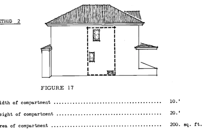
20.セャセ METHOD 2
r--- ..
'I·:··:····
I I '. I I . I I • I • I;t:1
I
t
U
;
I I FIGURE 17 Width of compartment •••....•...•...••.•••..•.•• 10. ' Height of compartment .•...•...•...•...•••...•• Area of compartment ..•...••..• 20.' 200. sq. ft.Note 4: It will be イ・セ・ュ「・イ・、 from the analysis of space 11 - 12 that it is not
practical to consider any area of much less than 300 sq. ft. due to the
limitations of Table 1. Keep i ng the same proportions for the
compart-ment and ゥョ」イ・。ウゥョセ the area we get:
Area of compartment ••.•.•..•••.•••••.•.•.•....•..••.••... Area of openings •.•...•.•.•.•..•...••..•....••....•...
29<). sq. ft. 26.8 sq. ft. Percentage of operu.ngs ••.•.•.••••.••••.•..••••••.••••...•••• YNイセ
39
-Separation required by Table 1
·
...
4.,
to boundarySeparation required by Table 2
·
...
N.A.Separation required by Table 3
·
...
N.A.
B U I L DIN G 1 5 METHOD 1 FIGURE 18 Width of compartment .•...•.••••セ ••.•••••••...•.•••..••• Height. of compartment •••..•••...••....••.•••..•••••.•••••• Area of compartment .•.•....••....•...••...•••.•..••••••••••• Total area of openings
Percentage of openings 41. 5' 21.5' 893. sq. ft. 107. sq. ft. 12NUセ
Separa tion required hy Table 1
·...
8.7' to boundarySeparation required by Table 2
·...
N.A.
- 40 METHOD 2
CJ
FIGURE 19 Width of compartment ...•..••.•....•...••...•.• Height of comparJtment .•....•.•...••..••..•••.•..••.••...•• Area of compartment •...•.•...•••••...••••...•..••.•.•. Total area of openingsPercentage of openings 17. I 20.
,
340. sq. ft. 94.6 sq. ft. RXNWセSeparation required by Table 1
·...
II. I to boundarySeparation required by Table 2
·...
7.65' to boundarySeparation requi.red b,\ Table 3
·...
10.3' totalNote 5: This example points up the difficulties that arise when applying the
tables to small buildihgs.
SUMMARY
TABLE 1
o
F S EPA RAT ION SBuilding 14: Building 15:
The maximum value is 4.' to the boundary The maximum value is 11.' to the boundary
-Total separation required:
41
-4.' + 11.'
=
15.'Note 6:
TABLE 3
Table 2 is not applicable in the instance.
ANALYSIS
o
F
42
-SPA C E
Note 1: Building 1 is f'ulIy compartmented at the area under consideration.
Note 2: Building 9 is uncompartmented into floors.
and the garage are enclosed.
MMセMGMMM
However, the stairwell
BUILDING 1
FIGURE 20
Note 3: The enclosed stairwell will not contribute to the radiation hazard.
Width of compartment .•••••..••••.••.•..••..••••••••••••••••• Height of compartment ••...••.•••...•...••••.•.••.•••• Area of compartment ...••••.•....•..••...•.•.•••....••.••• Total area of openf.ngs
p・イ」・ョエセァ・ of openings 23.' 8.
,
184. sq. ft. 27 .5 sq. ft. 15.%Separation required by Table 1
·...
6.6' to boundnrySeparation required by Table 2
·
...
N.A.pz
Note 4:
43
-However, the area of the com;mrtment is only 11:\4. sq. ft. It would be
more accurate to expand the wall area and keep the Rrea of openillgs
constant. This procedure would have the following result:
Area of compartment .•..•..•.••.••••....•••••.•••.••...•••••• 275. sq. ft.
Total area of openings Percentage of openings
...
.
.
.
.
..
.
...
.
....
..
...
...
.
...
.
.
...
27.5 sq. ft .
Separation required by Table 1
·...
4.,
to lot lineSeparation required by Table 2
·
...
N.A.Separation required by Table 3
·...
N.A.B U I L DIN G 9
Note 5:
FIGURE 21
The stairwell will not contribute to the radiation hazard.
Height of compartment ••..•...•...•.•...••••• Width of compartment ••••••.••..••••••••••••.•.•.••••...••••.
Area of compartment .•.•....•••...••... Total area of openings
Percentage of openings