Design, Construction and Installation of a Mechanical Shutter and
Design of a Medical Room Door Support system for BNCT Facility at
the MIT's Reactor
byWilliam Waller Carson IV
B.S., Mechanical Engineering at
Worcester Polytechnic Institute, Worcester MA (1998)
SUBMITTED TO THE DEPARTMENT OF MECHANICAL ENGINEERING ON
NOVEMBER, 1999 IN PARTIAL FULFILLMENT OF THE REQUIREMENTS FOR THE DEGREE OF
MASTER OF SCIENCE IN MECHANICAL ENGINEERING
AT THE
MASSACHUSETTS INSTITUTE OF TECHNOLOGY
FEBRUARY 2000
Copyright @ 1999 Massachusetts Institute of Technology.
All rights reserved.
Signature of Author:
6
Department Certified by:/7
Accepted by: of Mechanical Engineering November 4, 1999Pro r Otto K. Harling Thesis Advisor
Professor Peter Griffith Thesis Advisor
Professor Ain A. Sonin Chairman, Department Committee on Graduate Students
MASSACHUSETTS INSTITUTE OF TECHNOLOGY
MITLibraries
Document Services Room 14-0551 77 Massachusetts Avenue Cambridge, MA 02139 Ph: 617.253.2800 Email: docs@mit.edu http://Iibraries.mit.edu/docsDISCLAIMER OF QUALITY
Due to the condition of the original material, there are unavoidable flaws in this reproduction. We have made every effort possible to
provide you with the best copy available. If you are dissatisfied with this product and find it unusable, please contact Document Services as soon as possible.
Thank you.
Design, Construction and Installation of a Mechanical Shutter and
Design of a Medical Room Door Support system for a BNCT Facility at
the MIT's Reactor
by
William Waller Carson IV
Submitted to the Department of Mechanical Engineering
on November 4, 1999 in Partial Fulfillment of the
Requirements for the Degree of Master of Science in
Mechanical Engineering
ABSTRACT
A mechanical shutter system was designed, manufactured and installed; the
manual drive system for the mechanical shutter was designed and manufactured; the medical room door supports were designed and analyzed for a boron neutron capture therapy medical facility. The designs for these components went through numerous iterations to conform to changing design requirements, to reduce cost in manufacturing and to reduce installation time and labor.
Thesis Supervisor: Otto K. Harling Title: Professor of Nuclear Engineering
Thesis Supervisor: Peter Griffith
Acknowledgments
I would like to thank Professor Otto K. Harling, for helping me find my path with
this thesis. He allowed me to experience many opportunities that I would not have had
without his guidance. I now have had experience with everything from material venders,
to patient radiations to mixing and shoveling concrete. I would also like to thank
Professor Peter Griffith, who was always a good sounding board for ideas, a great source
of information, and a constant support of my endeavors.
I would like to thank the staff at the MIT Nuclear Reactor Lab and the Fission
Converter Project for their help though out my time working there. I would also like to
Table of Contents Abstract 2 Acknowledgments 3 Table of Contents 4 List of Figures 7 Chapter 1 10 Introduction
1-1 Boron Neutron Capture Therapy 10
1-2 Thesis Objectives 12 1-3 References 12 Chapter 2 14 Mechanical Shutter 2-1 Introduction 14 2-2 Problem Statement 14 2-3 Previous Work 17 2-4 Design Process 20 2-4-1 Mechanical Shutter 20
2-4-2 Manual Backup Drive System 31
2-4-3 Safety Concerns 33
2-5 Manufacture of Shutter 34
2-6 Installation of the Shutter Blocks 36
2-7 Installation of the Through Shaft for the Manual Drive System 41
2-8 Testing 43
2-9 References 43
Chapter 3 45
3-1 Introduction 45
3-2 Problem Statement 45
3-3 Previous Work 45
3-4 Design Process 46
2-4-1 Medical Room Door 46
2-4-2 Manual Backup Drive System 53
2-4-3 Safety Concerns 53
3-5 Installation of the Door Support System 53
3-6 Floor to the Medical Room 53
3-7 References 54
Chapter 4 55
Strength of the High Density Concrete Bocks Manufactured by the Fission Converter Beam Staff
4-1 Background 55 4-2 Testing 56 4-3 References 57 Summary 58 Reference 59 Appendices: 61 Chapter 2
A2-1 Calculations to Determine the Geometry of the Front Bars 62 A2-2 Information on the Bearings used for the Mechanical Shutter 64
A2-3 Calculations of the Center of Mass for the mechanical Shutter 66
A2-4 Calculations to Determine the Deflection of the Mechanical Shutter 68 A2-5 Calculations of Force to Operate the Ball Screw Drive for the
Mechanical Shutter Manually 71
Chapter 3
A3-2 Calculations of Factor of Safety for the Saddle component 74
A3-3 Calculations to Determine the Deflection in the Medical Room Door 76
A3-4 Equations to Determine the Number and Size of Bolts to Mount
the Saddle for the Medical Room Door Cantilever Beam 78
A3-5 Calculations to Determine the Geometry of the Ramp and the
Door crack for the Medical Room 80
Chapter 4
List of Figures Chapter 2 Mechanical Shutter Figure 2-01 Figure 2-02 Figure Figure Figure Figure Figure 2-03 2-04 2-05 2-06 2-07 Figure 2-08 Figure 2-09 Figure 2-10 Figure 2-11 Figure 2-12 Figure 2-13 Figure 2-14 Figure 2-15 Figure 2-16 Figure 2-17 Figure 2-18
Medical Room without the Mechanical Shutter (some blocks have been removed for visibility)
Cross section of elements that reside in and around the Cave, includes the Fission Converter Tank, the Filter Moderator, Collimator with the Water Shutter, the Mechanical Shutter in the Open Position, and the Support Block
Cross Section of the Mechanical Shutter in the Closed Position
Photograph of the area outside of the Water Shutter and Collimator where the Mechanical Shutter will be installed, in front of the Water Shutter is the Air Transport System to install components into the Cave
Schematic of the Horizontal Mechanical Shutter Schematic of the Slanted Mechanical Shutter
Mechanical Shutter in the Open Position (some blocks have been removed for visibility)
Mechanical Shutter in the Closed Position (some blocks have been removed for visibility)
Photograph of the Collimator and Water Shutter
Schematic of the Mechanical Shutter System with the Bottom Block highlighted
Cross Section of the Support Block showing the cut out for the Fill/Drain Line of the Water Shutter
Drawing of the slot in the back of the Support Block
Photograph of the bottom end of the Mechanical Shutter with two Bearings showing
Original Concept of the Mechanical Shutter
Photograph of the Mechanical Shutter showing the slots on the reactor side where the vent pipe of the Water Shutter will pass by the shutter
Schematic of possible radiation stream paths with out the Back Shield Bars Schematic of blocked radiation stream paths with the Back Shield Bars Schematic of the Mechanical Shutter System with the Back Shield Bars
Figure 2-19 Figure 2-20 Figure 2-21 Figure 2-22 Figure 2-23 Figure 2-24 Figure 2-25 Figure 2-26 Figure 2-27 Figure Figure Figure 2-28 2-29 2-30 Figure 2-31
Schematic of the Mechanical Shutter System with the Front Horizontal Bars highlighted
Schematic of the Mechanical Shutter System with the Side Supports highlighted
Photograph of the Left Side Support where the Fill-Drain Pipe from the Water Shutter penetrates the support
Drawing of the Through Shaft, the Hand Crank is not shown
Drawing of the Hand Crank with out the Through Shaft attached by the chain
Photograph of the Shutter after the lead was cast, and before the concrete was added
Photograph of the Shutter and the Support Block being delivered to MITRII Photograph Depicting the Installed Side Supports with the Nuclear Reactor
and Collimator shown behind the supports
Photograph of the temporary shielding so that the Reactor could power up with out the Mechanical Shutter in place
Photograph of the Installed Support Block Photograph of the Installed Shutter System
Photograph of the Drive System for the Mechanical Shutter mounted in place
Drawing of the Through Shaft with Components Specified
Chapter 3
Medical Room Door Figure 3-01
Figure 3-02 Figure 3-03 Figure 3-04
Drawing of the original support system with a post, the mount to the containment wall is not shown for clarity
Drawing of the supporting wall blocks for the support system for the Medical Room Door
Schematic of the Cantilever Truss
Scans of the Proposed Drive and Trolley System
Chapter 4
Concrete Strength
Appendix
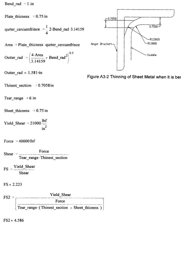
Figure A2-01 Cross-Section of the Mechanical Shutter Blocks and Bars Figure A2-04 Cross-Section of the plates that make up the Mechanical Shutter Figure A3-02 Thinning of Sheet Metal when it is bent
Figure A3-03a Deflection Plot of the Main I-Beam when the Door is closed Figure A3-03b Deflection Plot of the Main I-Beam when the Door is open Figure A3-03c Deflection Plot of the Cantilever I-Beam at Maximum Loading
Figure A3-03dTotal Deflection of the Medical Room Door at three points in its travel Figure A3-04 Schematic of the Cantilever Beam System that depicts critical dimensions
Chapter 1 Introduction
1-1 Boron Neutron Capture Therapy
Boron Neutron Capture Therapy (BNCT) is a process by which cancerous cells are killed with minimal damage to surrounding cells. This method is of interest in areas of the body where operations are difficult, such as the brain and for invasive tumors such as glioblastoma multiforme (GBM). This method of cancer treatment was first suggested in 1936.1 BNCT requires a 10B atom attached to a cancer-seeking compound. Any cancer-targeting compound can be used as long as it can deliver enough 10B atoms to the cancerous cells. The higher the concentration of 10B atoms that can be delivered to the cancer cells in comparison to the surrounding cells the better.
BNCT works in the following way. When a neutron is injected into the Boron ten
(10B) rich environment and is absorbed by the 10B atoms it changes into an excited state of 11B, noted as "'B*. The "B* atom is a highly unstable form of the Boron atom. When it decomposes, it primarily becomes an excited state of Lithium seven (7Li*). Like "B*, 7Li* is a highly unstable atom which transforms into 7Li with a gamma ray given off.
The other possible decay path of the "B* atom, will fission directly into a 7Li atom. The
two possible decay paths also release short-range but energetic ions. The range of the alpha particles range is so sort-range that it typically will terminate the cell that the 10B atom resides in, and or the adjacent cell. BNCT spares cells more distant than about ten micrometers; therefore, it is considered a cellular tumor targeting therapy.2
The BNCT process requires a neutron source, which currently is produced by a nuclear reactor. In order to get a pure epithermal neutron stream, the raw radiation being emitted from the reactor is modified by filtering out all other types of radiation. The undesired radiation includes fast neutrons and gamma rays. This filtering process at MITRII is accomplished by use of a Filter Moderator and a photon shield. This filter filters out all but the epithermal neutrons that this process requires.
Once a suitable neutron beam is generated, it must be collimated to the patient position. This is done with a collimator that is tapered at an angle of 65.37 degrees. This
device is also used as a shutter to stop the fast neutrons and some radiation when the system is not in use. To reduce the radiation still further when the system is not in use, the volume of the collimator is filled with water. This volume is called the Water
Shutter. Water is used because the hydrogen of water tends to slow and absorb the fast neutrons.
The portion of this project that is covered by this thesis is the design and
installation of the fast shutter, the design of the drive system for the fast shutter, and the shielding door for the Medical Room along with its suspension system. Both the "Fast" Mechanical Shutter and the Medical Room Door suspension system are to be installed in the new Medical Room at MIT's nuclear reactor. Currently there is a medical room located below the reactor in the basement. The new Medical room will be on the beam tube floor of the reactor and it will use a fission converter for its neutron source. Because of the high intensity, both the shutter and the door to the Medical Room must be able to block high intensities of radiation.
The new Medical Room mechanical shutter needs to be designed and constructed so that the facility will be safe and reliability provide a controllable dose of radiation to the patient. The Medical Room door needs to be designed and constructed so that when the patient is being irradiated within the Medical Room, the staff will not receive
significant doses of radiation. The Medical Room door will protect the staff by
preventing radiation from leaking out of the Medical Room through the entrance hallway. Jerry White, another Mechanical Engineering graduate student, has worked on earlier designs for the mechanical shutter and door for the Medical room. He concluded that a horizontal shutter consisting of lead, steel, concrete and polyethylene would be the most desirable design to pursue.3 Balendra Sutharshan4, and Michelle N. Ledesma5 concluded that such a shutter would attenuate the beam to approximately one milli-rem per hour. Jerry White also concluded that an all steel door hung by trolleys would be the best design for the door of the Medical Room.3
What this thesis will cover is the final design, construction and installation of the Mechanical Shutter, manual override for the shutter, and the design of the door support structure and door to the Medical Room along with an override for the door.
1-2 Thesis Objectives
This thesis will cover the design through the installation phases of a "fast" mechanical shutter for the Medical Room at MITRII. This shutter will be the final shutter to block the neutron beam used in the cancer treatment known as Boron Neutron Capture Therapy (BNCT). This thesis will also include the design of the Medical Room Door. This door will contain the radiation that is released within the Medical Room that is generated by the neutron beam. Both the Shutter and the Door must be driven
mechanically and have manual backups to ensure the patient and the medical staff can operate the system even if a power failure occurs.
In order to complete the fast shutter, complete engineering drawings, bearing sizing and selection, and drive system sizing and selection must be completed and sent out for manufacturing. The shutter has six major components. These components are; the shutter block, bottom block, two side supports, bearings, the electrical drive system and the manual drive system. The shutter, bottom block, the side supports and the manual drive system need to be designed and manufactured. All the components need to be assembled and installed.
The door to the Medical Room needs to be designed. Along with the door, the frame for the door needs to be designed and analyzed for stresses and failure states. Trolleys need to be selected for the door and an electric drive mechanism needs to be found. The door and support need to be designed so that minimal radiation is allowed to pass out of the medical room. Along with the electric drive, a manual drive system needs to be designed or purchased for the door.
1-3 References
1. Locher, G.L., "Biologic Effects and Therapeutic Possibilities of Neutrons," Am. J. Roentgenol, 36:7 1936.
2. Kiger, William Steadman, "Neutronic Design of a Fission Converter-Based Epithermal Beam for Neutron Capture Therapy", Nuclear Engineering Thesis, MIT, 1996
3. White, Jerry R., "Conceptual Engineering Designs for a Mechanical Shutter, a Medical Room Door, and a Water Shutter for a Fission Converter-Based
Boron Neutron Capture Therapy Medical Facility", Mechanical Engineering Thesis, MIT 1999
4. Sutharshan, Balendra, "Engineering Design if a Fission Converter-Based Epithermal Beam for Neutron Capture Therapy", PhD. Thesis, MIT, 1998
5. Michelle N. Ledesma, "Medical Room Design for a Fission Converter-Based Boron Neutron Capture Therapy Facility", B.S. Thesis, MIT, 1998
Chapter 2
Mechanical Shutter
2-1 Introduction
The "fast shutter" is the device that turns on and off the neutron beam that is generated within the nuclear reactor at MIT and delivered to the Medical Room. This shutter in the closed position attenuates the neutron beam by a factor of about three orders of magnitude. Two other shutters are used to fully attenuate the neutron beam, a boron containing shutter in front of the fission converter fuel, and a water shutter in the main collimator. These two shutters provide a further attenuation of about three orders of magnitude.' In the shutter's open position, there is a insert in the aperture that continues to collimate the neutron beam until it finally exits the system of shutters and filters that purify and directs the beam onto the patient position.
2-2 Problem Statement
In order to build the fast shutter, complete engineering drawings, bearing sizing and selection, and drive system sizing and selection must be completed. The appropriate parts need to be sent out for manufacturing. The shutter and the components that form the final shielding for the inside of the medical room need to be designed and
Collimator
(occupying the area of the Cave)
Neutron Beam Line
2-01 Medical Room with out the Mechanical Shutter (some blocks have been removed for visibility)
The shutter also needs to cover most of the entrance to the "cave" located on the main floor of the reactor where the blanket neutron facility once was located. (The cave is the area within the reactor housing in which the fuel tank, the filter moderator and the collimator are located.) Figure 2-01 shows the Medical Room with some blocks removed for clarity. In this figure is shown the area of the cave that is filled with the collimator and the water shutter, the area in front of the cave will be occupied by the Mechanical Shutter. Figure 2-02 shows the stack of components that are within the cave, and includes the Mechanical Shutter blocks.
Fission Converter Tank Support Mechanical Shutter Collimator Proton Shield Water Shutter Filter Moderator Block
2-02 Cross section of elements that reside in and around the Cave, includes the Fission Converter Tank, the Filter Moderator, Collimator with the Water Shutter,
the Mechanical Shutter in the Open Position, and the Support Block
This area is not as well shielded because of the lack of mass between the reactor core and the outer environment. In order to provide enough shielding the shutter must be fifteen and three quarter inches thick and must overlap the edges of the cave sides. The fast shutter is not the only device that attenuates the neutron beam, but it is the last one to be removed before a patient can be irradiated. The shutter's internal construction must have the part of the shutter that faces toward the medical room made out of lead, while the most of the rest of the shutter is made out of concrete. The open position must have a conical section that continues to collimate the beam. This opening must have six inches of lead around its circumference. In the closed position, the shutter must be made out of borated polyethylene or some other fast neutron absorbing material on the reactor side,
and lead on the patient side. Figure 2-03 shows a cross section of the Mechanical Shutter in the closed position.
Concrete
4" Lead
Polyethylene
or other fast 6" Lead
Neutron absorber
Steel
2-03 Cross Section of the Mechanical Shutter in the Closed Position
The shutter must move from the open to closed position in a time of ten to fifteen seconds. The design of the shutter must also take as little space in the medical room as possible. The shutter must also be manually closeable, in case of a power failure or malfunction in order to protect the staff and the patient.
2-3 Previous Work
The shutter has gone through some major modifications in its design. In Jerry White's thesis,2 the different possibilities are discussed in detail for shutters that can be placed in front of the Collimator that is shown in Figure 2-04.
2-04 Photograph of the area outside of the Water shutter and Collimator where the Mechanical Shutter will be installed
From the results of Jerry's thesis it was determined that a horizontal fast shutter should be used, such as shown in Figure 2-05. (Other alternatives were a vertical shutter and a curricular shutter.)
2-05 Schematic of the Horizontal Mechanical Shutter
With this information, one other possibility was looked at. This design would have the shutter at a five-degree slant as shown in Figure 2-06.
0jj
jQ0
I__
2-06 Schematic of the Slanted Mechanical Shutter
The benefit to that design is if a power failure should occur, gravity would assist in the closing of the slanted shutter. However this design was much more complicated and it was decided to go with a horizontal shutter. The shielding of the shutter, its geometry,
Block I
[IL.
1
ETI . -~ i~
the bearings, the drive system and the manual back up to close the shutter incase of a power failure was also examined in detail.
2-4 Design Process
2-4-1 Mechanical Shutter
The shielding of the shutter was most important. In order for the shutter to adequately reduce the radiation from the collimated beam, the shutter was made with a plug that was manufactured with different materials so that the intensity of the beam and the background radiation coming from the reactor could be attenuated. Refer to figure
2-03 that is on a prior page to get a visual understanding of the cross section of the plug and
the way the shutter was designed to reduce radiation from entering the Medical Room. The plug was designed with a step so that there would be no streaming of the radiation beam. The plug was also designed to be nine inches larger in diameter than the beam so that all the radiation would have to go through most of the shielding that the shutter provides. The materials originally selected to make the plug were about 7.5 inches of
lead on the patient side and the same amount of borated polyethylene on the reactor side. The rest of the shutter is designed with four inches of lead on the patient side of the shutter that keeps the background radiation of the cave at reasonably low levels. The remainder of the space was filled with Borated concrete. Around the beam port of the Mechanical Shutter 3.75 inches of lead is placed to add to the shielding of the lead insert that will continue to collimate the neutron beam. The total amount of lead will add up to
about six inches of lead to provide shielding for the neutron beam. This is comparable to the Collimator for shielding around the area of the neutron beam. The beam port is
designed to accept the lead insert that will collimate the neutron beam, and can be
replaced for varying shapes and sizes of beams. The final weight of the shutter is 30,200 pounds.
A requirement for the shutter is to have a two-inch overlap with the cave so that
the amount of radiation passing around the edge of the shutter from the cave is stopped or at least greatly reduced. By combining the upper block to the shutter, the overlap had to cover the upper portion of the cave as well as the sides. The shutter is required to move a
total distance of 52 inches because the aperture of the shutter, when the shutter is closed, must also be two inches away from the opening of the cave. The shutter had to be one hundred thirty two inches long, and have space on either side to travel a distance of at least 52 inches. The total length required for the "Fast" Mechanical Shutter to operate is
236 inches while the Medical Room is only 156 inches wide. To accommodate the travel
of the shutter the walls had to be notched so that the shutter could open and closed as it was intended to do. By notching the walls, or rather casting the wall blocks around a notched form, the shielding of the Medical Room was then compromised to a degree. To solve this problem extra shielding was added to the left (facing toward the reactor) outer side of the room and the shutter was designed to fill the notch on the right side when the beam is on. See Figures 2-07 and 2-08.
2-07 Mechanical Shutter in the Open Position (some blocks have been removed for visibility)
IMIs&-r',l
Shuftr2-08 Mechanical Shutter in the Closed Position (some blocks have been removed for visibility).
Since the collimator and the water shutter were installed into the cave before the fast shutter, the shutter had to avoid interfering with the fill and vent pipes from the water shutter that pass through the area that the fast shutter occupies (see Figure 2-09).
/
Water Shutter Vent Pipe\
Water Shutter Fill Pipe2-09 Photograph of the Collimator and Water Shutter
The water shutter has its fill line near the floor. The fill line pipe is 2.375 inches in diameter. This means that the support block (see Figure 2-10) needs to accommodate the pipe while still providing enough shielding and support for the fast shutter.
SUPport BIock \
I III I
2-10 Schematic of the Mechanical Shutter System with the Bottom Block highlighted
Placing the fill line on the extreme side of the collimator away from the control side of the medical room helped the shielding problem. This allows the shortest length of pipe to be exposed to minimal radiation of the cave and it keeps it far from the beam line. The pipe then goes into a notch cut out of the bottom block on the lower edge, which runs the pipe out of the shutter system. See Figure 2-11 for a view of the fill line notch in the
Support Block.
7
Waer Shutter F11P pe Noch I
2-11 Cross Section of the Support Block showing the cut out for the Fill/Drain Line of the Water Shutter
LI I I
The vent pipe for the water shutter is located on the top of the water shutter and comes out of the collimator centered in the cave. This pipe sticks out from the reactor face and the support block must fit over it so the block may be raised and lowered. For this reason a slot was milled into, the support block so that as the block is positioned between the frames the pipe transverses the slot. See Figure 2-12 for a view of the vent pipe notch.
I I
Back Notch for the Vent Pipe of the Water Shutter
2-12 Drawing of the slot in the back of the Support Block
The interface between the support block and the shutter has changed as well. It was originally a tongue and groove joint. This allowed for less streaming of the neutron beam. As the bearings were added to the shutter system, however, it became obvious that there was insufficient shielding on the side of the shutter with the two sets of bearings, to protect the patient from being improperly irradiated. Therefore, it was decided to use a step joint rather than a tongue and groove joint. The height of the step was equivalent to that of the bearings. Figure 2-13 shows the step in the shutter and the bearings that the shutter rides on.
> Bearings
Step
2-13 Photograph of the bottom end of the Mechanical Shutter with two Bearings showing
This allows for added shielding for the double bearings and prevents the streaming of the neutron beam. Figure 2-28 shows the Support Block with the rails attached, the rails and the step in the Support Block line up with the bearings and the step of the Mechanical Shutter.
The upper block was combined with the shutter to make the system easier to install and to reduce cost. Figure 2-14 shows the original concept for the shutter.
/r
o 0 .
o0 - - - - - -- - - - lc 0
.I0 -10
By combining the blocks the part count was reduced by one major item, the complexity
of the system was reduced, and the options for the drive system were increased. By combining the two blocks, the upper block no longer needed to be manufactured.
Making the shutter the upper most block is a benefit, this is because the drive system can be placed on top of the shutter or in the space directly above the shutter. This allows the drive mechanisms to be placed internal to the Medical Room. This reduces the space allocated to the shutter system. The absence of the upper block adds a void that can be used for the air return vent for the Medical Room.
The shutter needs to have a vertical slot similar to the support block so that during installation it can pass the vent pipe of the water shutter. Figure 2-15 shows a picture of the vertical slot in the Mechanical Shutter.
Horizontal Slot Vertical Slot
2-15 Photograph of the Mechanical Shutter showing the slots on the reactor side where the vent pipe of the Water Shutter will pass by the shutter
Once the shutter is in place, the vent pipe still protrudes into the shutter's planned area. This is because the water tank needs to vent the air in the Water Shutter tank, and the
only path that is available is out the front of the cave and up the face of the reactor. To accommodate the vent pipe, the shutter needs to have a horizontal slot cut out for the vent. Since the shutter travels horizontally, a slot is needed in the back of the shutter to
allow it to open and close the beam properly. This slot opens up a path for background radiation coming from the cave to escape into the room from the top of the shutter (see Figure 2-16).
RWdiaton
2-16 Schematic of possible radiation stream paths with out the Back Shield Bars
To remedy this problem the back shield bars were added (see Figure 2-17).
Back Shield Bar
Radiation Stream Harizontal Stat tn the
CUlliator
Shuter
2-17 Schematic of blockbed radiation stream paths withou the Back Shield Bars
- -- ,
- - - - -- =.=--- - -~
7]
/~ Bac dd Bm\2-18 Schematic of the Mechanical Shutter System with the Back Shield Bars highlighted
They are made out of steel that is designed to reduce the gamma and neutron radiation to tolerable levels. These bars have to be added last because they interfere with the
insertion of the support block and the shutter during installation (see Figure 2-18). Two front horizontal bars (see Figure 2-19) are designed and installed on the patient's side of the medical room.
FUnI HIIz ntU
2-19 Schematic of the Mechanical Shutter System with the Front Horizontal Bars highlighted
These tie and support the two sides of the shutter system together. The top bar is also designed as a guard for the fast shutter to decrease the possibility of tipping onto the
1III~
~--zJv
patient. Refer to Appendix A2-1 for calculations that determined the geometry of these bars. The reactor face prevents the shutter from tipping away from the patient. The
second bar was added to add rigidity to the system and to provide a place for bolting a safety cover and a final collimator for the beam to allow more flexibility of the beam type.
With the elimination of a separate upper block, the larger shutter is prone to tipping. Since the upper block is now added into the shutter construction, the aspect ratio of the shutter has increased so that preventative steps had to be considered to prevent the shutter from tipping over. It was determined that the upper front bar would suffice to prevent the Mechanical Shutter from tipping over. If at any time the shutter should rub against the bar, the system should be thoroughly examined to find what happened and to derive a solution so the problem does not continue to exist.
Two front bars where placed in front of the shutter. The top one is the only functional bar to restrain the shutter, while the other will be used to mount a final sheet
over the face of the shutter to protect staff and patents from the shutter.
The two side supports (see Figure 2-20) encompass the ends of the support block and allow the shutter to slide into the two sides. The supports bolt into the reactor face and to each other by way of the front bars.
2-20 Schematic of the Mechanical Shutter System with the Side Supports
Each of the two supports has a bottom plate with a pin that connects the two side supports to the bottom block. This aligns and connects the system to the whole unit. The pins are located on a bottom sheet of steel that connects the whole bottom of the side
support. Since the side supports will be lowered into place after the collimator and water shutter are in place a slot had to be made in the bottom of the left side support when facing the reactor from the Medical Room (see Figure 2-21).
.eft side Suppor Water stter FO pe CoDInaor
2-21 Photograph of the Left Side Support where the Fill-Drain Pipe from the Water Shutter penetrates the support
The bearings that were selected roll on cylindrical rails so that debris will slide off the rail and the bearings act like a tank's tread. The bearings are designed to pivot and to accept some misalignment. Refer to Appendix A2-2 for more information on the
bearings used by the Mechanical Shutter. The center of mass for the shutter was calculated as well to ensure the bearings would not be over loaded and that the shutter would be properly supported. Refer to Appendix A2-3 for calculations on how the center
of mass for the Mechanical Shutter was determined.
Since the weight of the shutter is so large, 30,200 pounds, and the bearings position should be toward the ends of the shutter to reduce the amount of radiation absorbed, it became important to ensure that the shutter could span the distance required without the possibility of a failure accruing. After the deflection calculations were computed, it turned out that a steel box around the shutter would be sufficient to support
the shutter as a whole. Refer to Appendix A2-4 for calculations on the deflection of the Mechanical Shutter.
Chain drives, pneumatics and ball screws where all considered. The ball screw drive was chosen, as it is clean, reliable, repeatable and accurate. The ball screw has the disadvantage that the drive takes up space inside the Medical Room and needs to have it's shaft penetrate the wall of the Medical Room to allow for manual closure of the fast shutter. The ball screw works with an electrical motor that is connected to the drive byway of a worm gear. This gear is attached to a "nut" which when turned by the motor will move the threaded shaft in and out depending on the direction the motor is turning.
2-4-2 Manual Backup Drive System
In order to get Nuclear Regulatory Commission (NRC) approval to use the Medical Room the shutter must have a manual closure system that can be activated from outside the Medical Room. Described below is a plan to operate the Mechanical Shutter manually.
The Manual Backup System turns the ball screw system backwards from normal use to drive the shutter. In this case the "nut" is held in place when there is a power failure due to an automatic break system. The screw now can be turned and this would push the "nut", which is attached to the Mechanical Shutter, back and forth to operate the shutter.
To gain access to the screw, a shaft had to be made to extend out of the Medical Room so that the operators could manually operate the shutter. This is a penetration in the shielding of the room, so a stepped shaft had to be placed in the wall so that radiation would not stream out of the hole. Figure 2-22 shows the manual backup shaft that penetrates the wall of the Medical Room and extends to the Linear Actuator Ball Screw Device.
S dI. supprit Wall
U-Joint E9 - - - -. --....
(oA
2-22 Drawing of the Through Shaft, the Hand Crank is not shown but a chain
connects the shaft to the crank by way of the cog on the left side of the shaft and near the pivot of the crank
The clearance around the shaft had to be very small to reduce radiation streaming. On either end of the hole are bearings to support and to take the axial load that the shutter puts onto the screw and shaft. Outside of the Medical Room, the shaft is translated to a height so it can easily be operated by the personal of the Medical Room. Figure 2-23
shows the Hand Crank of the Manual Drive System.
0
2-23 Drawing of the Hand Crank with out the Through Shaft attached by the chain
The crank arm is pinned to the wall so that when the shutter is operated normally (with an electric motor), the shutter will move rather than the manual override device. In the case
of an emergency, the operators would only have to pull the pin and then turn the crank manually using the handle that is attached to the arm.
The thrust bearing was mounted near the drive system and a universal joint was added to the shaft so the shaft would be more compliant to the alignment of the
equipment. Without this joint, the possibility for the shaft locking into place rendering the entire manual drive system not operational would exist. The manual drive was changed from a chain fall to a crank that is translated from the shaft by a chain drive. This allows the operator to be unconcerned about where the chain is and where it is falling and be concerned only with cranking in a defined space by the wall.
To operate the manual closure the operators must first pull the pin that prevents the shaft from rotating normally, then rotate the shaft with the use of the crank. Since the shutter was installed and the drive was mounted, it was possible to predict the force required to turn the handle. It was calculated to be 20 lbs with a crank arm of eight inches for a gear ratio of 2:1. A brake on the motor prevents the motor from being backward driven which would remove any possibility of operating the shutter manually. Refer to Appendix A2-5 for calculations on the force required to operate the manual override for the Mechanical Shutter.
2-4-3 Safety Concerns
There is a concern of a mechanical or electrical failure while the shutter is in motion, resulting in the shutter impacting the end of the side support. The greatest velocity of the shutter is the max velocity of the drive system. With this assumption, the force the shutter will experience is 389,000 pounds. By adding 20 bumpers into the inside of the side supports the impulse is translated into 15,000 pounds of force which can be absorbed more easily that if there where no bumpers. The bumpers allow the shutter to slow down over a distance rather than almost instantaneously stop with an incredibly high force. This would result in an audible bang when the shutter hits the bumpers, but no permanent damage should occur. If the bumpers where not there, the shutter could derail and become impossible to operate until the shutter was remounted, the manual drive system would be destroyed, and it is possible that some of the Medical Room blocks could shift or even break.
Other concerns were raised with the idea that the shutter would be moving back and fourth with a large impulse, this impulse could be dangerous. The shutter could slice and break most anything in the way because of this large impulse. The solution to this problem was to cover the area with a sheet metal to prevent objects from interfering with the shutter.
2-5 Manufacture of Shutter
For the fast shutter to become a reality a series of steps had to be carried out. The first part, the design of the shutter, was complete. The second was to engineer drawings. The drawings for the fast shutter blocks were made by Yakov Ostrovsky3, with the
ongoing assistance of the author. The third task was to approach industry to get quotes for the shutter. Two companies agreed to make bids. The two companies were APEC in Hingham and Artisan Industries Inc. in Waltham. The companies needed to make the shutter and machine the bottom block. The companies came back with vastly different quotes therefore the lowest bidder got the job, APEC of Hingham.
The support block was cast in Canada at Patriot Forgings. This block was made within eight weeks of the order being placed. The block was shipped to APEC when they were awarded the bid.
APEC clamed that Patriot Forgings of Canada did not properly heat-treat the
support block and therefore the support block was warping while it was being machined. They tacked on an additional fee for heat-treating the bottom block again. The designs had been changed slightly during the production of the fast shutter and the machining of the bottom block, however these changes were made before the job was begun. The shutter was manufactured with the front sheet of lead and the lead around the neutron beam port being poured at the same time. This is one of the changes that was made to the shutter when it was being manufactured. Figure 2-24 shows the shutter with the lead cone attached to the lead sheet in the front of the shutter.
2-24 Photograph of the Shutter after the lead was cast, and before the concrete was added
Slight changes continued to be made to the shutter as design changes were made and manufacturing simplifications where being made. There should have been enough time to complete the shutter blocks, APEC was unable to deliver the shutter on time. The shutter was due to arrive at MITRII during the first half of the May shutdown of the reactor (two months after the bid was awarded). The shutter was not completed until after the May reactor shutdown, so shield blocks were placed at the opening to the cave to stop the radiation from entering the work environment and permit reactor operation.
While the shutter was experiencing delays at APEC, the engineering drawings of the side supports and the front bars that are used to connect them together were
completed. This job was given to Artisan Industries Inc. of Waltham as they where already manufacturing the collimator and water shutter for the Medical Room. The side supports are not complicated pieces so they were manufactured in only four weeks and cost $11,250. They were ready to ship to the MITRII with the collimator (this was when the shutter was due originally).
The Shutter was finally completed on June 18, two months late, for the final cost of $7,950. A group of people from MITRII went to APEC to inspect and test the fast shutter before it was delivered. Figure 2-25 shows the Mechanical Shutter and the Support Block arriving at MITRII.
2-25 Photograph of the Shutter and the Support Block being delivered to MITRII. 2-6 Installation of the Shutter Blocks
The side supports were completed before the shutter was completed so the side supports were brought in to the contaminant area and with the assistance of Yakov Ostrovsky, and Edward Block4, the side supports were installed. The ties that connect the front of the side supports and the bottom pins was connected together with a beam to hold the exact distance that the bored holes in the support block needed fore correct
orientation. The supports were positioned as close to the reactor as possible to reduce the possibility of streaming or neutrons and gamma rays. It took longer than expected
because the floor of the reactor room and the face of the reactor were not flat. The total time to install the side supports was approximately one day with three to four people. Figure 2-26 shows the Support System installed in front of the Collimator.
2-26 Photograph Depicting the Installed Side Supports with the Nuclear Reactor and Collimator shown behind the supports.
Once the side supports were in place, the Corner 1 and Corner 2 blocks could be poured right outside of the Side Supports. These blocks added shielding to the reactor and needed to be in place before the reactor could go back on line. These blocks used the back and side of the side supports as one of the forms and became part of the side support unit. The right side support when facing the reactor from the Medical Room needed a ventilation duct and two conduits for cabling to control the shutter and there was a pipe added to create a void to allow the drive shaft of the ball screw to pass through the wall. The shutter was not completed during the outage so blocks had to be added to the front of the collimator to add temporary shielding for the reactor (see Figure 2-27).
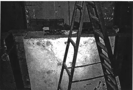
2-27 Photograph of the temporary shielding so that the Reactor could power up with out the Mechanical Shutter in place.
At the outage in July, the shutter was complete. After the temporary shielding blocks were removed, the support block was lifted and lowered into place between the side supports and onto the pins. The block fit well. The support block was then lifted so that high-density grout (with half iron ore dust and half cement) could be added under the block. This grout added additional support to the block between the support points. Figure 2-28 shows the Support Block installed.
>4
2-28 Photograph of the Installed Support Block.
The bearings were attached to the shutter (as shown on Figure 2-13), which had been removed for shipping. Once the bearings were installed they were wiped down with alcohol to clean them of any contaminates. The rails on the support block were wiped down as well and lubricant was added to the bearings. The shutter was then moved into position and lowered onto the support block.
Once the shutter was installed, the back shield bars were added. In order to align and mount the bars it was necessary to add eye bolts to the top edge so that the crane could be used to support them as the holes in the reactor face were drilled and anchors were mounted. The bars were then bolted into the reactor face and the side supports. Figure 2-29 shows the Mechanical Shutter's Blocks all installed.
2-29 Photograph of the Installed Shutter System.
The shutter was then tested by pulling and pushing the shutter back and forth against the bumpers that were installed into the side supports. It is possible for one strong person to open and close the shutter without help, however since it takes about 200 lbs of force to operate the shutter it is easily done with four people. It was found that the shutter rubbed the left side support when facing the reactor from the Medical Room. This was caused by the lack of flatness of the reactor face and the floor when the side supports where being installed. In order to solve this problem the side support had to be ground down until the shutter could pass without interference. About an eighth of an inch was removed and the shutter could pass freely.
The linear actuator ball screw was then mounted using two angle brackets that were made to mount on top of the shutter. This would cradle the drive, and would have enough adjustability to align the drive in the correct location. The linear actuator is white in the following figure, while the mounting brackets are black. The mounting bracket is connected directly to the top of the Mechanical Shutter. Figure 2-30 shows the drive mounted on the Mechanical Shutter.
A
2-30 Photograph of the Drive System for the Mechanical Shutter mounted in place
Once the drive was mounted, it became possible to determine what force would be required to operate the shutter manually outside of the Medical Room. This was done
by running up the drive to the end of the side support and measuring what torque was
required to move the shutter. The resulting torque was 80 inch pounds and the force required to open the shutter was calculated to be 20 pounds of force acting on an eight inch radius.
2-7 Installation of Through Shaft for the Manual Drive System
The installation of the through shaft was done in multiple steps. First, the tubing was installed into the blocks that would form the final penetration. (See Figure 2-31 for part names)
Inner Wall
Right Side Support Large pipe cast in wall Outer Wall Rda
Bearing
Large Tube Plate
Beaig Universal Joint Plate
/ Shaft
Inner Components 0
Age Brackets
Small Tube
Figure 2-31 Drawing of the Through Shaft with Components Specified
Since the inner wall block (next to the right side support when viewed from the Medical Room) was already poured with a large pipe cast in it, a small tube needed to be mounted and grouted into position using a hole that was drilled into the right side support as a reference. The larger tube then can be slipped over the smaller tube with the flange acting as an interface. RTV calking then can be added around the large tube, and then the new outer wall block can be formed so the block can be poured. The outer end of the large tube should be supported from the form.
The remainder of the through shaft can be installed later when all of the parts had been manufactured. The installation process is relatively straightforward. First, the shaft is inserted into the penetration in the walls. Then the radial bearing plate is test fitted with the bearing in place to align the shaft in the center of the penetration. The positions
for the anchors are marked and then the parts are removed. Once the anchors are installed, the shaft and the outer components can be installed.
The inner components are first assembled outside of the shutter cavity, then the universal joint is attached to the end of the shaft which connects the through shaft system together. By attaching the clevis to the end of the linear actuator that is mounted to the shutter, the position for the holes that mount the angle brackets to the right side support can be marked. By removing the inner assembly, the holes in the right side support can be drilled and taped. Once again, the inner assembly is mounted onto the end of the shaft and then it is connected to the drive system.
By adjusting the position of the short inner shaft, using the clearance in the drilled
holes in the thrust bearing plate, the thrust bearing support, and the angle brackets, the clevis will meet the drive system. If needed the drive system could be adjusted on the shutter by using the slotted mounting brackets used on the drive mount.
The manual crank can be assembled and mounted around the end of the through shaft at almost any position because the chain can be rotated and trimmed to fit. The chain that connects the Through Shaft to the Hand Crank is used to determine the final length between the two components. When the two components ate connected by the chain, the hand crank is extended until the chain is taught and the positions for the
anchors are marked through the holes in the hand crank base. The hand crank is removed and the anchors are installed. Once the anchors are in place, the hand crank is mounted to the wall after the chain was installed again. Finally, a pin with a spring-loaded ball is put into the hole of the hand crank arm that fit into the hand crank lock. At this point, the drive system can be tested and the manual system to operate the "Fast" Mechanical Shutter can be tested and used.
2-8 Testing
Testing of the shutter was performed at APEC and at MITRII. The testing at
APEC was to ensure that the shutter fit together with the support block so that there was
little or no overlap between the front and back planes of the two pieces with the bearings attached. While the shutter was mounted to the support block, a starting force test was preformed. It took only 200 lbs force to start the shutter rolling. The shutter was measured to determine the as-built dimensions. The overall height of the shutter determines the height of the lentil blocks for the Medical Room.
2-9 References
1. Sutharshan, Balendra, "Engineering Design if a Fission Converter-Based Epithermal Beam for Neutron Capture Therapy", PhD. Thesis, MIT, 1998
2. White, Jerry R., "Conceptual Engineering Designs for a Mechanical Shutter, a Medical Room Door, and a Water Shutter for a Fission Converter-Based Boron Neutron Capture Therapy Medical Facility", Mechanical Engineering Thesis, MIT 1999
3. Ostrovsky, Yakov, Personal Communication November 1998 through October
1999
4. Block, Edward, Personal Communication November 1998 through October
Chapter 3
Medical Room Door
3-1 Introduction
The door to the Medical Room is the last line of defense from unwanted neutrons and gamma radiation escaping into occupied areas of the building. The door needs to be operated quickly within 30 seconds to open or close and needs to have a manual override so if the electrical mechanism fails it is possible to open or close the door manually. The door should take up as little space as possible and must reduce the radiation to safe levels outside of the room. The door is approximately 16 tons, so the support for the door will be designed to take the loading while minimizing the floor space consumed by the support.
3-2 Problem Statement
The door to the medical room needs to be designed, and built. Along with the door, the frame needs to be designed and analyzed for stresses to prevent the possibility of mechanical failure of the support beams. Trolleys need to be selected for the overhead frame and a drive mechanism needs to be found and acquired. The door and frame need to be assembled and installed in the Medical Room so that minimal radiation is allowed to pass out of the medical room. Then the system must be tested so that the door can be deemed safe for the staff of MITRII and the Medical Room will not be compromised while using the door or the medical facility. A manual backup for the drive mechanism is required in case of power or mechanical failure. Safety concerns need to be addressed to prevent injury. The floor to the Medical Room needs to be designed for minimal
radiation to pass under the door, while maintaining a smooth floor contour.
3-3 Previous Work
The plan for the door for the Medical Room went through many iterations in the conceptual design. The possible ways the door would work included hanging it either from one or both sides, sliding the door outward away from the Medical Room, and
hanging it on an overhead rail and sliding it perpendicular to the Medical Room hall. The details of these designs can be found in Jerry White's Thesis.' The conclusion of Jerry White's Thesis was to build the door so it slid perpendicular to the Medical Room hall.
M.N. Ledesma worked on her Masters Thesis on the shielding work of the Medical
Room. Her work helped to determine what was required of the Door to the facility.2
3-4 Design Process
3-4-1 Medical Room Door
In order to position the door so that it could slide perpendicular to the Medical Room hallway, a support beam was placed directly above the path of the door. The obvious solution to this problem was to place a support on the reactor side of the door and on the far side of the beam on the wall of the containment building (see Figure 3-01). This idea was thought through and debated.
3-01 Drawing of the original support system with a post, the mount to the
containment wall is not shown for clarity
Plant Services at MIT was consulted and they suggested we talked to CBI Consulting3 for
further assistance. CBI came back with a plan to mount the beam to the wall as we had asked them. However, while they were working on the problem concerns arose about the
D20 lines that were in line with the path of the door. CBI also was asked to determine
the max possible point loading on the first floor of the containment building. CBI came back with a report stating that the floor could handle a load of 1,000 pounds force per
square foot, and 11,700 pounds for a concentrated load for the specified condition described in the appendix. Refer to Appendix A3-1 for CBI Consulting Inc.'s report.
In order to support the beam, either the lines would have to be cut and moved, or another beam would have to be added which avoided the D20 lines, or a new solution envisioned. A second vertical beam would support this end of the beam; but it would take up space in the narrow hallway. A design was created that would cantilever off one of the existing wall blocks (block WO-4) and would support the end of the beam that would carry the door (see Figure 3-02). This brought up the idea to use the other wall block, (block SI-1) to carry the load of the operator side of the main I-beam, this would remove the vertical beam that would be taking up valuable flour space in that area.
Door support blocks Wall Block WO-4
-Wail Block SM
3-02 Drawing of the supporting wall blocks for the support system for the Medical Room Door.
Replacing the cantilevered beam with rails mounted on the floor was considered. This would result in effect; act as speed bumps on the floor. These "speed bumps" would not be appropriate in this medical facility.
Variations of cantilever beam
The cantilever beam support system was designed to prevent using the outer wall as support for the door. The design was as a large upside-down L shaped structure with ribbing to give it support. An I-beam would be placed on top of the stem of the L and this would be the cantilevered beam. The structure would be made out of a plate 0.75 inches thick. The structure would then be mounted with bolts through a Medical Room block so that they were placed under shear forces rather than normal forces. It was
designed this way because concrete anchors tend to pull out after a long time of high loads, and especially under cyclical loading. This was structurally acceptable, however it would be expensive for it would involve a lot of welding.
The next iteration was to replace the structure with a truss of I-beams (Figure 3-03 shows the part that is being discussed). This would be less expensive to build and would increase the strength and rigidity of the system, but it would be difficult to mount to the wall.
CanCtil Tuss
3-03 Schematic of the Cantilever Truss
The solution was to weld the truss to a plate of 0.75 inches of metal and mount it with bolts. This design was acceptable as well, however the number of bolts required to hold the system to the wall with the door in the furthest open position would be excessive. To reduce the need for through bolts the sheet of metal would be bent creating a back plate, the struts would be attached to a structural resembling an upside-down U or a saddle with squared off corners. This would accommodate the entire downward loading of the door and the additional amount due to the geometry of the cantilever, however 3 bolts would still be required on the far side of the saddle to prevent the door from settling to the floor.
For the saddle to support the required weight, a weld for joining the outer sheet to the top sheet would not be adequate. Bending the sheet was considered as that it would retain much of its strength. However to bend a 0.75 inches peace of sheet metal with an inch inside radius the thickness of the sheet metal would be fifty-eight hundredths of an inches thick. This should be adequate to support the loads, however to add safety to the system a 0.75 inches thick angle bar will be welded to the joint. This would be necessary
to prevent a tear from forming and eventually propagating down the length of the saddle and resulting in failure of the door at the flour. Refer to Appendix A3-2 for the
calculation of the factor of safety for the Saddle component of the Medical Room Door Support System.
Changes to the cantilever system were made to make installation of the support easier. By replacing the through bolts that hold down the cantilever with anchored bolts so that alignment ceases to be a problem. This solved an installation problem because drilling through strait holes with a tolerance of an eighth of an inch would be time consuming and difficult.
The concept of the overall door support design was created first. Then the maximum deflection was defined which defines the materials to be used. The proper I-Beams to use in the construction of the support system was determined this way. The deflection of the door was then calculated along its travel with the Main I-beam and the Cantilever I-beam as being the main influences in the deflection of the I-beam. Refer to Appendix A3-3 for the calculations that determined the deflection of the Medical Room Door. The number of bolts was decided upon a similar process, but in this case, the maximum impact of the door was calculated and then that force was translated to pulling and shearing of the bolts. Refer to Appendix A3-4 for the bolt sizing and placement for the Saddle for the Medical Room Door Cantilever Beam. The number of Bolts was verified using a vender's program. The bolt anchors were decided upon.
The operator side support is a concrete block wrapped in steel. This block is mounted to the wall next to the operators and is bolted down to the wall with the use of concrete anchors. The use of anchors here is not a problem since they will only be used for shear loading and not tension. The main I-Beam will attach to this support locking the door system together.
Drive systems for the Medical Room door that were considered included chain drives, liner actuators and pneumatics, but a combination drive and trolley system was finally chosen. This system was one of the cheaper options and was simple to integrate in to any overhead track design. To implement a manual backup opening system, a winch would be used to open and close the door in the case of an emergency. If the
winch was unable to overcome the motor, then a clutch would be added so that the drive could be disconnected from the trolley so the winch could operate as designed.
The following drawings in Figure 3-04 where faxed from Sissco of Summerville
NJ, a vender of Budget Electric Hoists and Trolleys. The only part that would be
required would be the trolley, and not the hoist that is attached to the system in the drawings. The quoted parts that would be required is two 115491-3.