HAL Id: hal-02536299
https://hal.archives-ouvertes.fr/hal-02536299
Preprint submitted on 8 Apr 2020
HAL is a multi-disciplinary open access
archive for the deposit and dissemination of sci-entific research documents, whether they are pub-lished or not. The documents may come from teaching and research institutions in France or abroad, or from public or private research centers.
L’archive ouverte pluridisciplinaire HAL, est destinée au dépôt et à la diffusion de documents scientifiques de niveau recherche, publiés ou non, émanant des établissements d’enseignement et de recherche français ou étrangers, des laboratoires publics ou privés.
Scale offset for frequency tracker
Hadj Elandaloussi
To cite this version:
Scale offset for frequency tracker
S.O.F.T
H. Elandaloussi
LERMA-IPSL, Sorbonne Universités, UPMC Univ. Paris 06, CNRS, Observatoire de Paris, PSL Research University, F-75005 Paris, France
A new method for wide frequency laser control is presented. A laser with P and S polarizations and an ultra-stable ULE made Fabry-Pérot interferometer (FP) are used to lock alternatively a laser frequency from one FP signal to the other by the mean of two acousto-optic modulators (AOM). The stability of the FP is by this way transferred to the laser. The servo-locking system overcome the free spectral range limit by switching from one Airy function to the second one. As the method covers as many free spectral range as desired, the laser frequency can be driven all over the laser gain curve.
Experimental setup and resolutions expected of the instrument are discussed.
Introduction
Since many years Fabry-Pérot interferometers (FP) [1] and Michelson like [2] are used to control lasers frequencies. Fabry-Pérot cavities (FP) are often used to lock laser frequencies because with a high finesse FP the gradient of the derivative of the transmission function is very large. The laser frequency is then usually locked on an atomic or molecule transition line. Many FP based locking methods are used like the Pound-drever-Hall (PDH) scheme[1] or frequency modulation (FM)[3] for example. But large length displacement of tunable FP in all these cases is an issue hard to solve. Usually the frequency tuning of a FP is limited by its Free Spectral Range (FSR) which can be adjusted thank to the thermal expansion coefficient of the FP cavity material and/or the Ceramic-PZT control which modify the length of the cavity.
Michelson interferometers can control laser frequency over range larger than the THz. They suffer of complexity and it is hard to reach ultra high resolution. Because the interferometric signal is a cosine the gradient of the sine function (derivative) used to lock the laser frequency is low and leads to locking weakness.
In both cases, the mirrors displacements to scan the laser frequency do not easily give the frequency shift.
Since two decade, ultra-stable FP cavity have demonstrated the ability to lock laser frequencies at very high resolution [4]. But only for fixed frequencies or limited tuning thanks to electro-optic modulators for example [5].
The system presented here eliminates the limits of both methods i.e Michelson like and FP. This is done by the use of two signals provided by polarization beam splitting and an ultra-stable cavity with fixed length to improve the laser frequency control.
The laser to be controlled is frequency shifted by two acousto-optic tunable filters (AOM) and locked alternatively on an Airy peak of the ultra-stable FP cavity derivative signals.
Very high accuracy and stability lasers are now commercially available. Today, high accuracy and stability of very wide scan are the goal [6].
The confocal FP cavity transmits a laser beam at frequency ν following equation (1). L is the cavity length of the FP, c is the vacuum speed of light, and k is an integer.
(1)
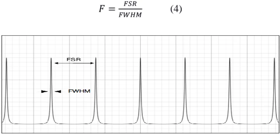
The Free Spectral Range (FSR) of a confocal FP is given by the following equation. (2)
The transmission function of a FP is expressed as equation (3) also known as the familiar Airy function.
(3)
And its finesse is expressed using the peak width at half maximum (FWHM) as : (4)
figure 1: Airy function peaks
figure 2: Derivative of the Airy function peaks
With two perpendicular lasers beams polarizations only one FP is useful. The FP is ULE made. Corning ULE glass is guaranteed 30 ppb max/K. At room temperature the ULE expansion coefficient (CTE) is close to zero and at its Tc temperature CTE=0 [2]. Because the stability depends on the cavity length, the ULE material is the best choice, it has already demonstrated sub-hz linewidth [7], [8].
Another solution is to build the cavity with stacks of different materials and could give a 0 CTE cavity. ZrW2O8 shows negative thermal expansion (-9 ppm/K) [7]. So disk of ZrW2O8 with the right size stacked with another material with CTE positive will compensate the expansion of FP cavity.
Another way to improve resolution is an active control of the length cavity but the cost rise.
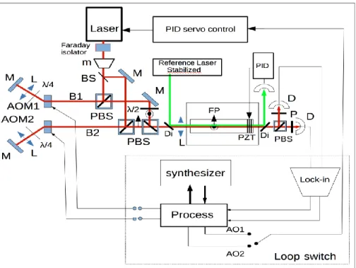
A cavity made in silica or Invar material can be used. In these cases the length cavity must be controlled by a reference laser and a loop acting on a PZT-ceramic (Fig 3). A Laser locked on a hyperfine line has a stability better than 10-12 over 100 s. If the length of the FP is locked on a maximum of transmission, the stability of the reference laser is transferred to the FP. While the FP cavity length is locked, one can use the setup described in this paper. Obviously the wavelength of the laser used to control the cavity length must be different to be easily filtered.
The purpose of this paper is to reach high resolution spectroscopy so an ULE spacer (FP) without suck disk or active length control will give us at least a 10-14 resolution which is already a huge progress for many applications at lower complexity.
As already describe in several papers an ultra-stable cavity is the heart of the setup.
Experimental setup and scan process
Figure 3: Active control Length FP Instrument setup, M mirror, L lens, PBS polarizing beam splitter, BS beam splitter, FP Fabry-Pérot cavity, AOM1-2 acousto-optic modulators, D detector, Di dichroic splitter, PZT piezoelectric stacks, m frequency modulator, AO1-2 analog output error signals.
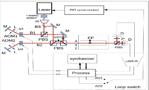
Figure 4: Passive FP Instrument setup, M mirror, L lens, PBS polarizing beam splitter, BS beam splitter, FP Fabry-Pérot cavity, AOM1-2 acousto-optic modulators, D detector, m frequency modulator, AO1-2 analog output error signals.
The FP cavity mirrors are chosen to give a Finesse cavity near 100 000. Mirrors are optically sealed to the spacer. Because it remain for the ULE material and mirrors coating very low expansion errors drifts [10],[11], the cavity is temperature stabilized at +/- 0.01°C at its Tc temperature.
The experiment is isolated from vibrations first with dampers between the experiment and the table and this table is equipped with active damping. To avoid index variations inside the cavity, the FP are emptied and placed inside a vacuum chamber. By this way pressure and index effects are minimized.
As shown in figure 4, if one use only one way beam inside the FP with two perpendicular polarizations (S,P) and detect these separately the free spectral range will be the same for both. The S and P polarized beams are mixed by the help of half wave plates and polarizing beam splitters. The two beams S,P are unmixed at the output of the FP by a beamsplitter and two polarizers with polarization axes at 90° of each other.
Each beam generated is shifted by its own AOM.
AOM1 and AOM2 are used in twice passes. The B1, S polarized beam, from AOM1 and the B2, P polarized beam, from AOM2 are mixed and sent to the FP. The AOM1,2 shift frequency values are provided by a digital synthesizer. Misalignment can be corrected by the uses of a mono-mode maintaining polarization fiber between the last PBS and the FP.
For 1-meter-length FP confocal cavities, the FSR is of 75 Mhz of the same order of magnitude of commercial acousto-optic modulators ranges. For example the ISOMET LS700-1109 model allows a shift band near 50 Mhz. The two path scheme allows 100 Mhz shift.
The laser beam is frequency modulated: a lock-in amplifier demodulates the detector signal and gives the derivative of the signal. This derivative is used as an error signal and is sent to the PID in order to lock the laser frequency.
The frequency of the laser is adjusted in order to lock the laser using the FP signals noted AO1, AO2 and detected respectively from the B1 and B2 beams. If AO1 from B1 is used, AO2 from B2 is monitored but not used to lock the laser.
AOM1=
L-n
1%FSR (5)
AOM1=
L+n
2%FSR (6)Where n2%FSR, n1%FSR are the frequencies driving the AOM1 and AOM2. When laser being locked and n2+n1=100% or n1+n2=200% the system can switch from one beam signal to the other. Let's show how n1 and n2 are driven to shift the laser frequency.
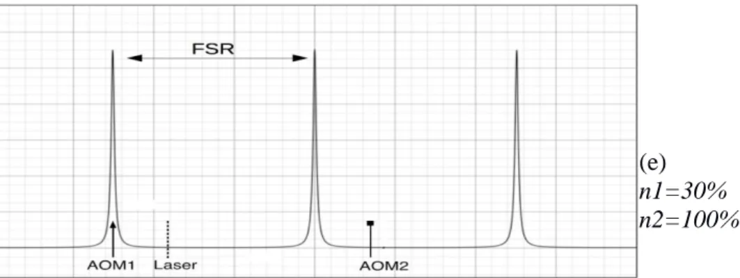
(a) n1=30% n2=100% (b) n1=100% n2=100% (c) n1=30% n2=100% (d) n1=30% n2=70%
(e)
n1=30% n2=100%
Figure 4 : Frequencies positions and Airy function transmission peaks of B1 and B2 beams during the scan process. The solid line arrow is the B1 frequency, the dashed line is the laser frequency, the squared is the B2 frequency,
At the beginning of the scan process (fig a), the shift produces by AOM1 is of -30% of FSR and the shift produces by AOM2 is of +100% of FSR. By this way, the two beam frequencies are apart from each other of 130% of FSR. (Other values can be chosen and would lead to same results). The B1 transmission peak drive a loop to lock the laser frequency (figure 4.a).
The laser frequency locked, the AOM1 frequency remains constant.
The AOM1 frequency is then step by step decreased. As the laser is locked on the B1 beam signal, the laser frequency increases to compensate the shift modification. After a total AOM1 scan of about -100% and because AOM2 shift remains of +100% of FSR both frequencies are apart from 200% of FSR. Therefore simultaneously, the FP transmits the B1 beam and the B2 beam, figure 4.b. By this way, the laser frequency has shifted of 70% of FSR. Then the loop may be switched from B1 signal to B2 signal. The B1 signal is then monitored but not used and the AOM1 frequency reset to -30% of FSR, figure 4.c. Now AOM2 is step by step decreased, increasing the laser frequency which exactly compensates the shift. When the AOM2 total shift is of 70%, the B2 and B1 beam are apart of 100%FSR (i.e one FSR), figure 4.d. Therefore the FP transmits the laser beam B1, the loop is switched again from B2 to B1. The AOM2 frequency is reset to +100% of FSR, figure 4.e. At this step the laser frequency has shifted of one FSR.
Figure 4.e is like figure 4.a, therefore the process can be repeated as many times as desired to cover ultra-wide spectral range.
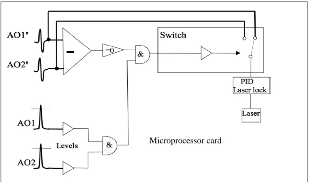
Switching method
In order to switch the laser lock from one signal to the other i.e from B1 to B2 signal, the signals are measured with their derivatives.
One have to compare the signals of both beams while the laser is locked and the scanning is performed to allow the switch only when the signal level of the new signal is equal to the one acting in the loop.
This will avoid errors from a “Nonius (Vernier) scale” effect.
So to perform the switch between the two signals, while the AOM is frequency decreased an electronic test is performed for each polarization i.e B1 and B2, when the FP signal of the polarization monitored is maximum and its derivative reach a value windowed around 0, the AOM is adjusted to reach the right values and then the loop lock is switched. By this mean the laser frequency is not affected by the switching. The laser frequency controlled by AO1 from B1 is now t at the same frequency but controlled by AO2 from B2.
Figure 5 : Switch card control
Discussion
As said above, Michelson interferometer allow wide excursion but the resolution is low. FP interferometers have high resolution but the excursion is low.
This method cut away the weakness of Michelson like and Fabry-Pérot interferometers tuned by length and gives an ultra-wide frequency range of tuning with high resolution. Furthermore the frequency scanning is driven by a synthesizer which mean that the steps are known with the stability and accuracy of the synthesizer itself. This is not the case with a PZT-ceramic scanning. The S.O.F.T method allows wide ultra-high resolution spectroscopy.
MAO are used here but an electro-optic-modulator could be used with PDH locking technique to improve the stability of the laser control.
[1] R. W. P. Drever, J. L. Hall, F. V. Kowalski, J. Hough, G. M. Ford, A. J. Munley, H. Ward,
Laser phase and frequency stabilization using an optical resonator, Applied Physics B, vol 31,
issue 2, pp 97-105, (1983)
[2] A. Henry, A. Valentin, M. Margottin-Maclou, and F. Rachet, “Tunable diode-laser spectrometer with controlled phase frequency emission,” J. Mol. Spectrosc., vol. 166, pp. 41–55, (1994).
[3] Louis Marmet, Alan A. Madej, Member, IEEE, Klaus J. Siemsen,
John E. Bernard, Member, IEEE, and Bradley G. Whitford, Member, IEEE, “Precision Frequency
Measurement of the S – D Transition of Sr with a 674-nm Diode Laser Locked to an Ultrastable Cavity”, IEEE Transactions on Instrument and Measurement, Vol. 46, No. 2, (1997)
[4] Li Jin, Yanyi Jiang, Yuan Yao, Hongfu Yu, Zhiyi Bi, and Longsheng Ma, Microprocessor card
Laser frequency instability of 2 10−16 by stabilizing to 30-cm-long Fabry-Pérot cavities at 578 nm, Optics Express, vol 26, No 14, 2018
[5] H. Stoehr,* F. Mensing, J. Helmcke, and U. Sterr,
Diode laser with 1 Hz linewidth, OPTICS LETTERS, Vol. 31, No. 6, 2006
[6] W. Gunton, M. Semczuk, and K. W. Madison
”A method for independent and continuous tuning of N lasers phase-locked to the
same frequency comb”, Optics Letters Vol. 40, Issue 18, pp. 4372-4375 (2015)
[7] B. C. Young, F. C. Cruz,* W. M. Itano, and J. C. Bergquist ,Visible Lasers with Subhertz
Linewidths, Physical Review Letters, vol 82, No 19, pp 3799-3802, (1999)
[8] J. Alnis, A. Matveev, N. Kolachevsky, Th. Udem, and T. W. Hänsch, Subhertz linewidth diode lasers by stabilization to vibrationally and thermally compensated ultralow-expansion glass Fabry-Pérot cavities, Phys. Rev. A 77, 053809 – Published 12 May 2008
[9] Koshi Takenaka, “Negative thermal expansion materials: technological key for control of thermal expansion”, Science and Technology of Advanced Materials, vol 13, num 1, 2012
[10] R. W. Fox, “Fabry-Perot temperature dependence and surface mounted optical cavities”, Optics Express 15023, Vol 17, No 17, (2009)
[11] A. D. Ludlow, X. Huang, M. Notcutt, T. Zanon-Willette, S. M. Foreman, M. M. Boyd, S. Blatt, and J. Ye, “Compact, thermal-noise-limited optical cavity for diode laser stabilization at 1x10(-15).” Optics Letters Vol 32, pp. 641–643 (2007)