Publisher’s version / Version de l'éditeur:
Vous avez des questions? Nous pouvons vous aider. Pour communiquer directement avec un auteur, consultez Questions? Contact the NRC Publications Archive team at
[email protected]. If you wish to email the authors directly, please see the first page of the publication for their contact information.
https://publications-cnrc.canada.ca/fra/droits
L’accès à ce site Web et l’utilisation de son contenu sont assujettis aux conditions présentées dans le site LISEZ CES CONDITIONS ATTENTIVEMENT AVANT D’UTILISER CE SITE WEB.
Proceedings of Newfoundland Electrical and Computer Engineering Conference
(NECEC '98), 1998-11-13
READ THESE TERMS AND CONDITIONS CAREFULLY BEFORE USING THIS WEBSITE.
https://nrc-publications.canada.ca/eng/copyright
NRC Publications Archive Record / Notice des Archives des publications du CNRC :
https://nrc-publications.canada.ca/eng/view/object/?id=8aecaa3f-333f-492b-bcfc-6444789e7b42
https://publications-cnrc.canada.ca/fra/voir/objet/?id=8aecaa3f-333f-492b-bcfc-6444789e7b42
NRC Publications Archive
Archives des publications du CNRC
This publication could be one of several versions: author’s original, accepted manuscript or the publisher’s version. / La version de cette publication peut être l’une des suivantes : la version prépublication de l’auteur, la version acceptée du manuscrit ou la version de l’éditeur.
Access and use of this website and the material on it are subject to the Terms and Conditions set forth at
A dynamic positioning system for ship model tests
A Dynamic Positioning System for Ship Model
Tests
J. Millan, B. Smith
Institute for Marine Dynamics
National Research Council
St. John’s, Newfoundland, Canada
[email protected]
[email protected]
June 5, 2002
1
Introduction
The Institute for Marine Dynamics (IMD) maintains an extensive set of facil-ities, which are used for model marine vessel and offshore structure testing. As part of these facilities, sophisticated instrumentation and control systems are used to reproduce the environment and the functionality of these vessels and structures. In early 1997, IMD began the development of a Dynanlic Po-sitioning (DP) System for model vessels. A DP system is a closed-loop control system that is used to automatically control a vessel’s thrusters in order to maintain a station or specified track. The control system senses changes in po-sition and heading which are due to the environmental forces acting upon the vessel; i.e. waves, wind and current. IMD has conducted two model tests which have utilized the DP system described in this report: the first was an extensive set of tests involving the Terra Nova FPSO (Floating Production, Storage and Offloading) vessel and the second was an unanchored semi-submersible. This paper will detail the design rationale, and some of the techniques utilized in the IMD DP system.
2
Design Rationale
Real-world DP systems include many features that we do not necessarily need to include in a model-scale system. Likewise, there are some elements that may need to be included in the model system which are not included in the real-world systems. The following sections describe briefly the elements that are required for the model DP system. Some design requirements which we felt were important at the beginning of the design were that the system would
be easy to use and it would supply visual aids to assist in tuning the control system.
3
System Block Diagram
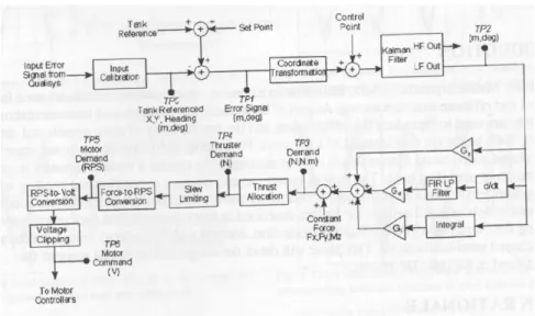
In the system block diagram (Figure 1) each line represents a vector quantity, since the full DP system is a 3-axis controller; i.e. surge, sway and heading (yaw). Error signals are computed by subtracting the observed position and heading (actual position and heading of vessel) from the setpoints (tank refer-ence - desired position and heading of vessel). The observed position, which is measured by a non-contact optical positioning system, and the setpoint, are specified in a tank-referenced coordinate frame. The tank- referenced error sig-nal must be converted to body coordinates to feed the PID controllers which also operate in body coordinates. The acronym Pill stands for Proportional, Integra! and Differential. Simply put, the controller combines a proportion of the error signal, the integrated error signal, and the differential of the error signal to form a control, or demand, signal that will be eventually applied to the motors. The control point is summed at this point, since the observed po-sition may not be the same point about which the model is being controlled. At this stage, the error signal is applied to a wave filter (Kalman filter) which is used to remove high-frequency (so-called first-order) wave energy. It is unde-sirable for the model thrusters to respond to wave frequency disturbances even though it is physically possible for our small DC servo motors to do so. In other words, the system should respond to the slow drifting movements of the model, but not to the vessel ’rocking’. In real-world DP systems wave filtering is of paramount importance, since it reduces wear-and tear on drivetrain com-ponents in thrusters as well as lowering overall fuel consumption. The filtered error signals are pushed through a Pill controller which has user-variable gains for each parameter (P , I, D). The next important block of the system is the thruster allocation logic. Thruster allocation refers to the process of taking the surge, sway and yaw demand signals from the pm controller and assigning them in some logical fashion to each of the propulsion thrusters. this process will be described in some more detail below. Since the model-scale thrusters are capable of very high angular accelerations, and the control signals at this point may contain high-rate signals, a block is added to limit the slew rates of the various thruster signals to that of the real-world thrusters.
4
Kalman Wave Filter
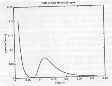
As stated, above the wave filter is used to remove first-order wave energy from the control signals, while allowing second-order (lower frequency) energy to remain. The power spectral density of a vessel’s motion in the surge axis is depicted in Figure 2 . There is a significant separation in the first and second-order components of the spectrum. A low-pass FIR filter could be used to
Figure 1: IMD DP System Algorithm and Block Diagram
do a reasonable job here, but good attenuation is gained at the expense of phase shift, which is detrimental to the stability of the control loop. Current DP technology for the most part utilizes a Kalman filter. The Kalman filter which incorporates a stochastic model of the vessel’s motion characteristics, can produce a prediction (optimal estimate) of the vessel motion so that there is little or no phase shift in the filtered signal. Another desirable quality of the Kalman filter is to remove white noise which originates with the measurement system.
5
Thruster Allocation
The purpose of thruster allocation is primarily to allocate thrusts to each control thruster in order to satisfy the total demands of the PID controller in Surge and Sway (Force) and in Yaw (Moment). In order to satisfy this function, the algorithm must take into account thruster geometry and individual thruster limits (maximums). In most cases, the number of control thrusters outnumbers that of the demand signals, so that there are more unknowns than knowns. The problem can be simplified by grouping or operating thrusters in pairs for example. When extreme forces are acting upon the vessel, there is often not sufficient thrust capability to meet all demands. In these instances, the thruster allocation logic must either split the demands or meet one demand 100%, while scaling the others back. For example, the general rule for a ship-shaped vessel is to correct the yaw demand at the expense of the sway or surge axes. This is because the ship will be aligned with oncoming wave and wind forces so as to minimize the total environmental load. In the case of a semi-submersible, Surge
Figure 2: IMD DP System Algorithm and Block Diagram
and Sway demands are given first priority since the environmental loading will not change significantly through yaw.
6
Implementation
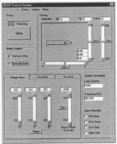
The DP system software was developed in Microsoft Visual Basic 5. The Kalman filter algorithm was developed in MATLAB, compiled with the MathSoft Inc.’s MATCOM compiler into C++ code. The C++ Code was compiled using Mi-crosoft Visual C++ 5 compiler into a windows dynamic link library (DLL) for use with the VB development environment. Windows NT was chosen as the operating system for its near real-time performance which is combined with its user-friendly user interface. The control code is executed at 50Hz with very little ’jiggle’ in the system timing. This is achieved by setting the process pri-ority to Real-Time in Windows NT .A screen-shot of the implemented control system is shown in Figure 3. The user has access to all pm tuning parameters (through on-screen sliders) while the control system is running, which allows for ”on-the-fly” tuning of the pm loops. A rea1-time graphical display plots the vessel in overhead view. The setpoint of the vessel can be manipulated through on-screen sliders. A stripcharting function allows for rea1-time control system tuning, monitoring and debugging. All off-line parameters, such as thruster calibrations. Kalman filter parameters. etc. are entered by the user through an Options screen which utilizes tabbed dialog boxes. These parameters. in addi-tion to the on line parameters (i.e. PID gains) can be stored to and retrieved from a configuration file on disk.
7
Conclusions and Future Work
This first version of IMD’s DP system software was very successful. Features to be added to new systems include thruster allocation for azimuthing thrusters; digital motion controller hardware; improved wave filtering; optimal control design; wind feedforward and water current modeling.
8
References
1. Brown. RG., (1983):”Introduction to random Signal Analysis and Kalman Filtering... John Wiley and Sons. ISBN 0-471-08732-7
2. Datta. I., Butt. S.. Millan. J. (1997): ” Dynamic Positioning Model Test Capability Demonstration at the Institute for Marine Dynamics’.. NRC/IMD Report TR-1997 -32. December.
3. Fossen. T.I., (1994): ”Guidance and Control of Ocean Vehicles.’. John Wiley and Sons. ISBN 0- 471-94113-1.
4. Gubbels, A. W., Ellis, D. K., (1997): ”Dynamic Positioning of an Offshore Vessel Model”.NRC/IAR Report LTR-FR-138, November 2