HAL Id: hal-02278318
https://hal.archives-ouvertes.fr/hal-02278318
Submitted on 4 Sep 2019
HAL is a multi-disciplinary open access
archive for the deposit and dissemination of
sci-entific research documents, whether they are
pub-lished or not. The documents may come from
teaching and research institutions in France or
abroad, or from public or private research centers.
L’archive ouverte pluridisciplinaire HAL, est
destinée au dépôt et à la diffusion de documents
scientifiques de niveau recherche, publiés ou non,
émanant des établissements d’enseignement et de
recherche français ou étrangers, des laboratoires
publics ou privés.
Single-step pulsed electrodeposition of calcium
phosphate coatings on titanium for drug delivery
Elia Vidal, J Buxadera-Palomero, Camille Pierre, Jm Manero, Mp Ginebra,
Sophie Cazalbou, Christèle Combes, E Ruperez, D Rodriguez
To cite this version:
Elia Vidal, J Buxadera-Palomero, Camille Pierre, Jm Manero, Mp Ginebra, et al.. Single-step pulsed
electrodeposition of calcium phosphate coatings on titanium for drug delivery. Surface and Coatings
Technology, Elsevier, 2019, 358, pp.266-275. �10.1016/j.surfcoat.2018.11.037�. �hal-02278318�
OATAO is an open access repository that collects the work of Toulouse
researchers and makes it freely available over the web where possible
Any correspondence concerning this service should be sent
to the repository administrator:
tech-oatao@listes-diff.inp-toulouse.fr
This is an author’s version published in: http://oatao.univ-toulouse.fr/24054
To cite this version:
Vidal, Elia and Buxadera-PAlomero, J and Pierre, Camille
and Manero, JM
and Ginebra, MP and Cazalbou, Sophie and Combes, Christèle
and
Ruperez, E and Rodriguez, D Single-step pulsed electrodeposition of calcium
phosphate coatings on titanium for drug delivery. (2019) Surface and
Coatings Technology, 358. 266-275. ISSN 0257-8972
Official URL:
https://doi.org/10.1016/j.surfcoat.2018.11.037
Single-step pulsed electrodeposition of calcium phosphate coatings on
titanium for drug delivery
Elia Vidal
a,b, Judit Buxadera-Palomero
a,b, Camille Pierre
d, José M. Manero
a,b,
Maria-Pau Ginebra
a,b,c, Sophie Cazalbou
e, Christèle Combes
d, Elisa Rupérez
a,b,
Daniel Rodríguez
a,b,⁎aBiomaterials, Biomechanics and Tissue Engineering Group, Department of Materials Science and Metallurgical Engineering, Universitat Politècnica de Catalunya (UPC),
Av. Eduard Maristany 10, 08019 Barcelona, Spain
bBarcelona Research Center in Multiscale Science and Engineering, Universitat Politècnica de Catalunya, Av. Eduard Maristany 10, 08019 Barcelona, Spain cInstitute for Bioengineering of Catalonia (IBEC), Barcelona Institute of Science and Technology (BIST), Baldiri Reixac 10, 08028 Barcelona, Spain dCIRIMAT, Université de Toulouse, CNRS, INPT-ENSIACET, 4 allée Emile Monso, 31030 Toulouse cedex 4, France
eCIRIMAT, Université de Toulouse, CNRS, Université Toulouse 3 - Paul Sabatier, Faculté des Sciences Pharmaceutiques, 35 Chemin des Maraichers, 31062 Toulouse cedex
9, France A R T I C L E I N F O Keywords: Calcium phosphate Titanium Coating Pulse electrodeposition Antibacterial agent Characterization A B S T R A C T
Metallic implants have some limitations related to bioactivity and bacteria colonization leading to infections. In this regard, calcium phosphate coatings can be used as carrier for drug delivery in order to improve the men-tioned drawbacks. The present work proposes the introduction of an antibacterial agent in the course of a pulsed
and reverse pulsed electrodeposition. Calcium phosphate coatings were prepared in 30 min using different pulse
waveforms (unipolar-bipolar), current densities (2–5 mA/cm2) and temperatures (40–60 °C). Mechanical
stabi-lity of the as-coated surfaces was studied in order to select the optimal electrodeposition conditions. Subsequently, selected coatings were loaded with an antiseptic agent, chlorhexidine digluconate (CHX), via a single-step co-deposition procedure. CHX concentration added to the electrolyte was adjusted to 3 mM based on the antibacterial efficacy of the loaded coatings evaluated in vitro with Staphylococcus aureus and Escherichia coli bacteria strains. Whereas the same chlorhexidine concentration was added to the electrolyte, results showed that
the amount of CHX loaded was different for each condition while release kinetics was maintained. The results of
this work demonstrate that a pulsed co-deposition strategy has great potential to modulate local delivery of antibacterial agents such as chlorhexidine digluconate, which may prevent early phase infections of metallic implants after insertion.
1. Introduction
Titanium and its alloys are the materials of choice for most ortho-pedic and dental applications due to their good biocompatibility with bone [1]. Poor osseointegration and infection around the implant, however, can affect its successful implantation. Many strategies have been proposed to either improve osseointegration or reduce bacteria colonization on the implant surface [2,3]. Multifunctional coatings, which can integrate both approaches, are a good option in order to enhance cell colonization while minimizing bacteria adhesion and proliferation [4,5]. In this regard, titanium (Ti) implants can be coated with calcium phosphates (CaP), which are recognized to be bioactive,
and at the same time, this coating can be used as a drug delivery system [6–9]. Calcium phosphate coatings can be obtained by several techni-ques, including sol-gel synthesis, electrophoretic deposition, electro-chemical deposition, plasma spraying and biomimetic process [10–12]. Among these coating processes, plasma spray deposition is the only technique commercially used for coating implants [13], but it suffers from certain drawbacks such as coating delamination, lack of uni-formity and limited control of the layer composition and structure due to the extremely high temperature processing [14]. Due to those lim-itations, research has been focused on alternative methods of deposi-tion.
In recent years, electrochemical deposition (ECD) has gained much
⁎ Corresponding author at: Biomaterials, Biomechanics and Tissue Engineering Group, Department of Materials Science and Metallurgical Engineering, Universitat
Politècnica de Catalunya (UPC), Av. Eduard Maristany 10, 08019 Barcelona, Spain.
E-mail address: daniel.rodriguez.rius@upc.edu(D. Rodríguez).
https://doi.org/10.1016/j.surfcoat.2018.11.037
attention due to the ability to deposit coatings on complex shape sub-strates at low temperature and with accurate control of the thickness and chemical composition, and it is relatively cheaper than other pro-cesses [15]. However, during conventional electrochemical deposition hydrogen bubbles (H2) are produced at the vicinity of the cathode
acting as a boundary layer which lowers the throughput of the ions. In order to circumvent this issue, pulsed cathodic electrochemical de-position has been used for coating titanium substrates [16–19]. Indeed the relaxation time (time off) between two unipolar pulses reduces the emission of H2. Furthermore during this period without current, ions
diffusion from the solution to the surface of the cathode is promoted, thus the uniformity of the ion concentration from the bulk solution to the cathode is increased [20–23]. As a result, a pulse cathodic elec-trochemical deposition process could produce coatings with higher uniformity and less porosity compared to direct current (DC) electro-deposition methods [24,25]. Moreover, coating adhesion to the tita-nium surface can be improved by using pulse reverse power. In this regard, changing the polarity of the current for a short time can pro-mote the growth of adherent particles from the coated layer [26–28].
Coated surfaces can prevent initial bacterial adhesion by a local release of an antimicrobial agent [8]. Chlorhexidine digluconate (CHX) is an antiseptic with activity against a wide of microorganisms, in-cluding Gram-positive and Gram-negative bacteria, and has a low risk of associated drug resistance [29]. One of the mechanisms that can explain its efficacy is based on the adsorption of cationic CHX molecule to phosphate groups of the bacterial cell wall [30]. CHX can be easily adsorbed on calcium phosphate coatings by soaking the samples in a CHX-loaded solution [31]. However, adsorbed CHX may be prone to be quickly removed by bodyfluids preventing prolonged drug delivery at the dose needed to avoid post-surgical infection development.
In order to delay the CHX desorption, it has been proposed to cover the CHX-loaded surfaces with a lipid layer [29]. Nevertheless, this hydrophobic layer might also prevent cell adhesion resulting in poor implant stability and osseointegration. An alternative approach for loading the antibacterial agent is by co-deposition with CaP, a metho-dology that incorporates CHX in the CaP coatings by adding CHX to the electrolyte used in the electrodeposition process [32].
Although many authors have explored the deposition of CaP by pulse electrodeposition, the present study is focused on the fabrication of an adherent CHX-loaded CaP coating by using pulsed and reverse pulsed current, working at low current densities and reduced processing time (30 min). To the best of our knowledge, so far there is no report on co-deposition of CHX/CaP coatings obtained by pulsed and reverse pulsed electrodeposition. The effect of temperature and current density on the morphology as well as on the coating adhesion to the substrate was evaluated on both unipolar and bipolar current waveforms. Based on the results, process conditions providing improved layer adhesive-ness were selected to study the CHX co-deposition. Furthermore, the drug release profiles were modelled and compared. Finally, in vitro biological assays were performed to determine both the cell adhesion
and the antibacterial response against S. aureus and E. coli.
2. Materials and methods 2.1. Sample preparation
Samples were prepared from grade 2 titanium (Ti) disks (10 mm diameter, 2 mm thickness) polished with silicon carbide papers from 400 to 1200 grit andfinally colloidal silica to obtain a mirror finish surface. Polished samples were ultrasonically cleaned in acetone, ethanol and ultrapure water. Before electrodeposition, samples were treated in NaOH 5 M solution for 24 h at 60 °C [33], rinsed with ul-trapure water and dried in a desiccator.
2.2. Pulsed electrodeposition
Pulsed electrodeposition of calcium phosphate coatings was per-formed in a solution prepared by mixing 0.042 M of Ca(NO3)2·4H2O and
0.025 M of NH4H2PO4with a Ca/P molar ratio of 1.67, at pH 4.2 [34].
The reagents were all analytical grade (Sigma-Aldrich, USA). The electrochemical deposition was conducted in an individual cell using a three electrode configuration, in which a platinum electrode acted as an anode, a saturated calomel electrode (SCE) as reference electrode and the titanium sample as cathode. Electrodeposition was carried out using a potentiostat (PARSTAT 2273, Princeton Applied Research, Oak Ridge, TN, USA) by pulsing the current for 30 min. Two different pulse wave forms were studied: unipolar pulse plating, hereafter termed PP, and bipolar pulse reverse plating where anodic and cathodic pulses are mixed, referred to as PRP (Fig. 1).
Different current densities and process temperatures were evaluated (Table 1).
Then, chlorhexidine digluconate 20% (w/v) (Sigma-Aldrich) was incorporated into the electrolyte solution at different concentrations: 0.3, 0.6, 1.5, 3, 6 and 12 mM, for selected electrodeposition conditions. After the electrodeposition, samples were removed from the electrolytic cell, rinsed with distilled water and dried at room temperature [32].
Fig. 1. Schematic representation of unipolar and bipolar pulse waveforms.
Table 1
Electrochemical parameters used for calcium phosphate coatings.
Conditions ion1(mA/cm2) ton1/toff1(s) ion2(mA/cm2) ton2/toff2(s) T (°C)
PP40_2 2 1/2 – – 40 PP40_5 5 1/2 – – 40 PP60_2 2 1/2 – – 60 PP60_5 5 1/2 – – 60 PRP40_2 2 1/1.6 −4 0.2/0.2 40 PRP40_5 5 1/1.6 −10 0.2/0.2 40 PRP60_2 2 1/1.6 −4 0.2/0.2 60 PRP60_5 5 1/1.6 −10 0.2/0.2 60
2.3. Physico-chemical characterization
The microstructure of the coatings was determined by X-ray dif-fraction (XRD) using a monochromatic Cu Kα radiation (Bruker D8
Advance Instrument, Germany) at a scan rate of 1°/s, in the 2θ range of 4–80°. The incorporation of CHX was confirmed by micro-Raman spectroscopy (LabRam Confocal Raman, Horiba Jobin Yvon, UK) with a 532 nm laser, a 600 grating and a ×100 magnification objective. Spectra were obtained from three scans of 60 s each. Moreover, samples before and after loading were also analyzed by micro-Raman to observe changes on the chemical composition.
The surface morphology of the coatings was examined by Zeiss Neon40 scanning electron microscope (SEM Carl Zeiss NTS GmbH, Jena, Germany) at a potential of 2 kV. Furthermore, cross-sectional SEM images of the different calcium phosphate coatings were obtained for the estimation of coating thicknesses by partially covering the sur-face of the samples during the electrodeposition.
The average surface roughness (Ra) was measured with a white-light
profiling system WYKO NT9300 (Veeco Instruments, Plainview, NY, USA) in vertical scanning interferometry (VSI) mode using a 50× ob-jective lens. Ten measurements were acquired for each sample at dif-ferent positions.
Fig. 2. XRD diagrams of pulsed electrodeposited coatings: a) PP60_5, b) PP60_2, c) PP40_5, d) PP40_2, e) PRP60_5, f) PRP60_2, g) PRP40_5 and h) PRP40_2.
Fig. 3. Cyclic voltammetry under potentiodynamic conditions [scan rate: 2 mV/s].
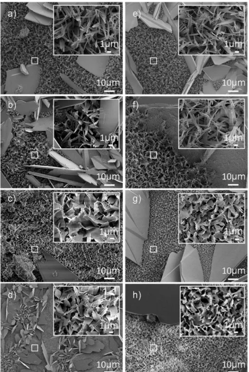
Fig. 5. SEM micrographs showing crystal morphology of calcium phosphate coatings on titanium substrates obtained by pulse plating at 40 °C and 60 °C: a) PP60_5, b) PP60_2, c) PP40_5 and d) PP40_2 and by pulse reverse plating at 40 °C and 60 °C: e) PRP60_5, f) PRP60_2, g) PRP40_5 and h) PRP40_2. A more detailed view (at higher magnification) is presented in each inset.
Table 2
Coating thickness and adhesion strength values of different electrodeposition conditions. Samples with the same symbol indicate no statistically differences
(p < 0.05).
Conditions PP40_2 PP40_5 PRP40_2 PRP40_5 PP60_2 PP60_5 PRP60_2 PRP60_5
Thickness (μm) 11 ± 1* 15 ± 1#,& 12 ± 1*,# 17 ± 2&,§ 17 ± 2& 22 ± 1∞ 14 ± 1*,#,& 21 ± 2§,∞
The adhesion strength of the CaP coatings to the substrate was evaluated by tensile test according to the ASTM F1147 international standard. Briefly, the coated Ti disks were bonded to cylindrical sample holders with FM 300K epoxy adhesive film (Cytec Engineered Materials, USA). The epoxyfilm was cured by heating the specimens up to 175 °C in 30 min and maintaining this temperature for 60 min. The tensile strength test was performed on a universal testing machine (Microtest MT, Microtest, Spain) at a constant cross-head speed of 2.5 mm/min. Three samples for each coating condition were tested to obtain average values of the adhesion strength. Coatings with higher adhesion strength were used to carry out the biological assays.
2.4. Biological characterization
2.4.1. Cell adhesion and coating degradation
Cell adhesion was conducted with Ti disks coated with the previous selected conditions without CHX. The assay was performed with human osteoblast-like SaOS-2 cells (ATCC, USA) cultured in McCoy's 5A medium (Sigma-Aldrich) supplemented with 10% v/v fetal bovine serum (FBS), 50 U/mL penicillin, 50μg/mL streptomycin, 20 mM HEPES and 2 mM L-glutamine, all from Invitrogen. Seeding was con-ducted at a density of 2 · 104cells/well, on triplicate specimens, and incubated for 6 h in a 48-well culture plate. Cells were lysed with
mammalian Protein Extraction Reagent (m-PER; Pierce, Rockford, IL, USA). The number of attached cells was quantified by using the cyto-toxicity detection kit LDH (Roche Applied Science, Germany). The lactate dehydrogenase (LDH) activity was determined by measuring the absorbance using a microplate reader (Synergy™ HTX Multimode reader, USA) at 492 nm and then, a calibration curve was used in order to obtain the results as cells number. Uncoated Ti samples were used as controls.
The degradation of the coatings was evaluated by quantifying the calcium and phosphate ions content on the cell adhesion assay super-natants (medium in contact with samples). Calcium concentration was studied by o-cresolphthalein complexone method [35,36]. This tech-nique is based on the formation of a colored complex with o-cre-solphthalein complexone in an alkaline medium. Absorbance was measured at 570 nm (Infinite M200 Pro, Tecan, Switzerland). On the other hand, phosphate colorimetric assay kit (Sigma-Aldrich) was used for measuring (650 nm) the amount of phosphate present in the sample supernatants.
2.4.2. Bacteria growth curves
The antimicrobial activity was tested against gram positive S. aureus (CCUG 15915, Culture Collection University of Göteborg, Sweden) and gram negative E. coli (CECT 101, Colección Española de Cultivos Tipo, Spain). Both bacterial strains were grown and maintained in Brain-Heart Infusion (BHI, Scharlab, Spain). Before each assay, bacteria were cultured and incubated overnight. Bacterial growth curve assay was performed in double-well culture plates [37]. Samples were immersed in 2 mL of diluted bacterial suspension adjusted to an absorbance of 0.02 ± 0.01 at 600 nm (106colony-forming units (CFU)/mL) using a
photometer (Laxco MicroSpek™ DSM, USA). The absorbance was monitored for 16 h by measuring absorbance at 600 nm with a multi-mode microplate reader (Synergy™ HTX Multimode reader, USA). Medium without bacteria and bacterial suspension were used as nega-tive and posinega-tive controls, respecnega-tively.
2.4.3. Agar diffusion test
The diffusion assay was carried out by adding 100 μL of inoculum to agar and BHI poured into petri dishes. Previously, optical density of each bacterial suspension (S. aureus and E. coli) was adjusted to 0.20 ± 0.01 at 600 nm, corresponding approximately to 108CFU/mL.
Triplicates of each condition were placed on the surface of the agar plates and incubated for 24 h at 37 °C. Untreated titanium samples and
Fig. 6. SEM micrograph of PP60_2 coating cross-section.
Fig. 7. Raman spectra indifferent wavenumber domains of CHX and CHX-loaded coatings: A) CHX in PRP40_2CHX, PP60_2CHX and 20% w/v CHX B) PRP40_2 and
coated disks without CHX-loading were used as controls. The result of inhibition was calculated by measuring the width of the inhibited zone around each sample.
2.5. In vitro drug release
The drug release was performed by immersing samples loaded with CHX (hereafter named PRP40_2CHX and PP60_2CHX respectively) in 1 mL of Tris(hydroxymethyl)methylamine buffer solution (TRIS, VWR International Ltd., UK) at physiological pH and 37 °C, under sink con-ditions [38]. At each time point, solution was withdrawn and replaced by fresh TRIS. The amount of CHX was determined from a calibration curve obtained by monitoring the absorbance of known concentration of CHX in TRIS buffer solution with a UV-spectrophotometer (Shimadzu model 3600, Tokyo, Japan;λ = 254 nm). Triplicates of each condition were used. Moreover, unreleased CHX was quantified by immersing one sample of each condition (from thefinal time point) in 1 mL of HNO3
0.1 M and then measuring the absorbance of the fully dissolved
CHX-loaded CaP coating using the corresponding calibration curve [29]. These values added to the total released CHX showed the real amount of CHX loaded into the CaP coating. After release, samples morphology was studied by scanning electron microscope (SEM, Quanta 450, Bruker, USA).
CHX release profiles were fitted to different mathematical models (Korsmeyer-Peppas, Higuchi and Kopcha). Korsmeyer-Peppas model (KP) can provide insights regarding the limiting drug release me-chanism. The concentration of drug released was correlated to Eq.(1), where Mt is the drug amount released at time t, M∞ is the maximum amount released from the material in these experimental conditions, k is a constant incorporating characteristics of the network system and the drug, and n is the released exponent that is indicative of the limiting transport mechanism. Mt/M∞ was calculated for each specimen and averaged for each condition using the concentration and time data of thefirst 60% of the fractional release in which the equation is valid [39].
= ∞
M /Mt ktn (1)
Higuchi model is represented by Eq.(2), where a is the diffusion constant. This model offers a good correlation with release patterns where Fickian diffusion is the predominant mechanism [40].
= ∞
M /Mt at0.5 (2)
Kopcha model can be used to study the contribution of the diffusion (A) and erosion (B) mechanisms. When the ratio A/B is higher than 1, the contribution of the diffusion is predominant (Eq.(3)).
= +
Mt At0.5 Bt (3)
Moreover, the release profiles of the two studied conditions have been compared using the difference factor f1and the similarity factor f2
from the model independent approach described by the FDA (Food and Drug Administration) and the EMA (European Medicines Agency). In Eqs.(4) and (5), n is the number of time points, Rtand Ttare the
dis-solution values of the reference and the batch respectively, at time t [41].
∑
∑
= ⎡⎣ − ⎤ ⎦⎡⎣ ⎤⎦ = ={
}
f1 |Rt Tt| / Rt ·100 t 1 n t 1 n (4)Fig. 8. a) Cell adhesion of SaOS-2 cells after 6 h of incubation. Statistically significant differences versus control samples are indicated with an asterisk. Evolution of ionic concentration in the cell culture medium b) calcium ions and c) phosphate ions. Symbols indicate samples with statistically significant differences (p < 0.05).
∑
= ⋅ ⎡⎣ + − ⎤⎦ ⋅ = −{
}
f2 50 log 1 (1/n) t 1(R T ) 100 n t t2 0.5 (5) The value of these factors should be between 50 < f2< 100 and0 < f1< 15 in order to consider the two release profiles comparable,
as reported by other authors [42].
2.6. Statistical analysis
All data presented in this study are given as mean value ± standard deviation. At least triplicate samples (n = 3) were used for statistical analysis, except for roughness study where ten samples were analyzed. One-way ANOVA followed by the Student's test was used to analyze the significant differences (p < 0.05) between group average values.
3. Results and discussion
3.1. Selection of coating conditions before CHX-loading
Selection of coating conditions was performed with samples without Chlorhexidine. Electrochemical deposition is based on the pH-depen-dent solubility of CaP. The pH is increased near the cathode due to the presence of hydroxyl ions generated by the reduction of water (Eq.(6) [43]. Consequently, acid-base and precipitation reactions lead to the formation of different CaP phases depending on the process conditions (Eqs.(7) and (8)) [20]. + −⟶ + − 2H O2 2e H2 2OH (6) + + ⟶ + − Ca2 HPO 2H O CaHPO ·2H O 42 2 4 2 (7) + + + ⟶ + − −
8Ca2 2HPO 4PO 5H O Ca (HPO ) (PO ) ·5H O 42 43 2 8 4 2 4 4 2 (8) Phase composition of the as-coated samples was studied by XRD (Fig. 2). The results confirmed the presence of sharp peaks
Fig. 10. Bacteria growth curves a) PRP40_2CHX with S. aureus, b) PRP40_2CHX with E. coli, c) PP60_2CHX with S. aureus and d) PP60_2CHX with E. coli.
corresponding to brushite phase (DCPD, CaHPO4·2H2O, according to
JCPDS n. 72-0713 brushite standard). Furthermore, the presence of peaks associated with octacalcium phosphate (OCP, Ca8(HPO4)2(PO4)4·5H2O, according to JCPDS n. 79-0423 octacalcium
phosphate standard) was confirmed. This can be due to an increase of hydroxyl ions concentration in the electrolyte which promotes the precipitation of OCP [20,44]. These calcium phosphate phases might have an influence in bone growth since they are known as precursors of HA formation [45].
Peaks were also assigned to the alpha titanium substrate (JCPDS card no. 89-2762). It is noteworthy that the peaks relative intensity can differ from standard patterns. This is described in the literature to occur in electrochemical processes due to the favored growth of the crystal perpendicularly to the substrate surface [46,47].
The microstructure of the coatings was observed by SEM. The images showed uniform surfaces without the presence of porosity. This was expected due to the reduction of H2bubble formation near the
surface of the cathode during the pulse and reverse pulse electro-deposition [48]. To confirm this effect, a cyclic voltammetry test was carried out. As shown in Fig. 3, for values under −1.3 V the linear
increase in the cathodic current density evidences the electrolysis of water and the formation of hydrogen bubbles [49]. The effect of the H2
bubbles is evidenced in Fig. 4a, representative of the CaP coating achieved on titanium by direct current (DC) without pulsing, in mean current conditions equivalent to those of samples PP40_5 and PRP40_5. As a comparison, samples treated in pulsed regimes, either without reverse pulse (PP40_5,Fig. 4b) or with reverse pulse (PRP40_5,Fig. 4c) do not show any of the surface defects evident on the DC-treated sample.
In the SEM analyses shown inFig. 5, two crystal morphologies are observed for all treated surfaces: a region composed of large platelet-like crystals of approximately 30μm in length and a region composed of needle-like crystals of around 5μm in length. The pulse waveform and current density do not seem to present a significant effect on the coating morphology. Conversely, the smaller crystals exhibit morphologic dif-ferences when the temperature of the process is modified. As the tem-perature is increased, the platelet-like morphology observed at 40 °C (Fig. 5c, d, g, h) is replaced with a needle-like morphology (Fig. 5a, b, e, f). This can be attributed to the increased diffusion rate of the ions in the electrolyte when temperature increases, promoting the nucleation and growth of needle-like crystals.
Coating thickness of samples obtained in different conditions were evaluated based on cross-section SEM images, with values ranging from 10 to 24μm (Table 2).
Results showed that, with increasing temperature up to 60 °C, the coating thickness increases. This is attributed to change of diffusion and reaction rate that can promote the layer formation [50]. Correspond-ingly, the thickness of the depositedfilms was increased by raising the current density (Fig. 6). This result was expected since the change of polarity may act as a stripping time in the PRP cycle, which selectively redissolve less adhered CaP particles [26].
Adhesion of the CaP coatings to the substrate is of the utmost im-portance for the implant to function properly in physiological condi-tions. The adhesion strength for PRP40_2 coating obtained by com-bining reverse pulses with low temperature and low current density was about 36 ± 4 MPa. Similarly, coatings obtained in PP60_2 conditions showed an adhesion strength of 35 ± 1 MPa (Table 2). Both conditions exceed the 22 MPa in tensile strength required by FDA Guidance for Metallic Plasma Sprayed Coatings on orthopedic implants [51]. Con-versely, thicker coatings obtained in PP60_5 and PRP60_5 conditions present both lower adhesion strength, probably due to coating dela-mination [11]. According to these results, the best electroplating de-position conditions were established to be at PRP at 40 °C and 2 mA/ cm2 and PP at 60 °C and 2 mA/cm2. In this regard, both coating
Fig. 12. Release of CHX from PRP40_2CHX (reversed pulses at 40 °C and 2 mA/
cm2) and PP60_2CHX (pulses at 60 °C and 2 mA/cm2).
Table 3
Parameters obtained from Korsmeyer-Peppas, Higuchi and Kopcha modelling of PRP40_2CHX and PP60_2CHX release curves.
Korsmeyer-Peppas model Higuchi model Kopcha model
n R2 a R2 A/B R2
PRP40_2CHX 0.422 0.998 0.074 0.996 ≫1 0.997
PP60_2CHX 0.250 0.991 0.056 0.949 ≫1 0.951
Fig. 13. SEM micrographs of PRP40_CHX coating a) before and b) after 15 days of release test in TRIS buffer.
Table 4
Factors of difference and similarity of PRP40_2CHX and PP60_2CHX conditions.
PRP40_2CHX/PP60_2CHX Specifications
f1 14.5 0–15
difference could be probably due to the effect of the reverse pulses which may present a higher increase of the pH at the vicinity of the cathode. For that reason, PRP40_2CHX condition may reduce the so-lubility of CHX which will result in a higher concentration of CHX in the coating [32]. These results are in accordance with the major anti-bacterial activity observed by PRP40_2CHX condition, which is 13% greater against S. aureus and 47% for E. coli (Fig. 11).
Cumulative release of CHX from the coated specimens was studied (Fig. 12). PP60_2CHX presented a burst release of CHX and showed the fastest release for the first 48 h, during which 61 ± 7% of the drug loaded was released. The stationary state was reached after 7 days. The drug released by PRP40_2CHX also presented a burst release for thefirst 8 h, although less pronounced than for PP60_2CHX. At this time point, the amount of CHX released was 28 ± 4%. After 3–4 days, the PP60_2CHX profile presented a less pronounced increase compared with PRP40_2CHX. These drug delivery systems provided a CHX sus-tained release compared with antibiotic loaded by conventional dipping method, since in the last case more than 80–90% of the antibiotics are released from calcium phosphate coatings within thefirst hour [56].
To characterize the release mechanism, the amount of drug released from each coating group wasfitted with the different model equations (Table 3). Resulting squared multiple correlation coefficient R2showed
that all studied models provided a better goodness of fit for PRP40_2CHX condition. For KP model, the value of n lower than 0.5, especially for PP60_2CHX showed that pseudo-Fickian diffusional me-chanism controlled the release of drug from coating [57].
Considering the dissolution of the coating observed by SEM at the end of the release studies (Fig. 13b), it was necessary to deepen the investigations and understanding of the mechanisms of drug release using other models as those proposed by Higuchi and Kopcha.
The A/B ratio obtained in the Kopcha model showed that if erosion phenomena exist, it is the diffusion mechanisms that prevail and lead to the release of chlorhexidine [58]. This information is confirmed by the results obtained with the Higuchi model. This model also showed that by ignoring thefirst hour of release (burst effect), the coefficient of Higuchi is higher for PRP40_2CHX than for PP60_2CHX showing a faster release for PRP40_2CHX.
Despite the differences in the release kinetic profiles of PRP40_2CHX and PP60_2CHX, the statistical factors f1and f2, showed
that the two kinetic profiles are statistically similar since f1< 15 and
f2> 50 (Table 4).
4. Conclusions
In this work, adherent calcium phosphate coatings loaded with CHX have been obtained by a one-step electrodeposition process on titanium substrates. The presence of DCPD and OCP was confirmed by XRD and Raman analyses. In addition, the presence of different phases in the coating can allow tuning its stability and resorption properties. Moreover, the amount of loaded-CHX can be modulated by adjusting the coating conditions without altering the release kinetics. Although erosion of the coating was observed after 14 days in a buffered solution, CHX is predominantly released by diffusion mechanism. This study also showed that CHX co-deposited with CaP did not alter the antimicrobial agent since both coatings exhibited a noteworthy in vitro antibacterial activity against S. aureus and E. coli.
Acknowledgments
The present study was supported by Catalan Agency for Management of University and Research Grants (AGAUR FI-DRG), project SGR2014 01333 (Catalan Government), project SGR 2017 SGR1165 (Catalan Government), BIOACTISURF project no. 14054394 of the Midi-Pyrénées Region and COST Action Ipromedai TD1305. The authors acknowledge the Spanish goverment for financial support through project MAT2015-67183-R (MINECO/FEDER), co-funded by conditions were selected for incorporating CHX and studying drug
re-lease and biological response. 3.2. Presence of chlorhexidine
Coatings loaded with 3 mM of chlorhexidine added in the electro-lyte were analyzed by Raman spectroscopy. For both coated surfaces, the incorporation of CHX was confirmed by the presence of a sharp peak at 1597 cm−1 in the Raman spectrum due to the C]C stretching
of aromatic ring (Fig. 7A) [52]. Raman spectra also confirmed the presence of OCP (958 cm−1, 967 cm−1) for both coating conditions and
DCPD (986 cm−1) for PP60 [53]. Moreover, loaded CHX has no
sig-nificant effect on the phase composition of the coatings (Fig. 7B and C). 3.3. Biological assays
3.3.1. Cell adhesion
Cell adhesion was studied for PRP40_2 and PP60_2 conditions in order to evaluate the cell attachment on coated surfaces without CHX (Fig. 8). Both coating procedures enhance cells attachment to the sur-face after 6 h of incubation. A significant difference was observed in cells attached on PP60_2 and PRP40_2 surfaces compared to titanium control. Topography and surface roughness were shown to affect os-teoblast-like cell adhesion (Fig. 8a). In this regard, PP60_2 had the highest surface roughness (Ra = 3.32 ± 0.39 μm) compared with that
of PRP40_2 sample (Ra = 2.07 ± 0.48 μm). In addition, both results
contrasted with the roughness of raw titanium samples (Ra = 38.3 ± 4.5 nm) (Fig. 9). The increase of the average surface
roughness for CaP-coated titanium may contribute to favor cell at-tachment [54]. Supernatant medium in contact with coated samples revealed a lower concentration of calcium ions compared with the in-itial medium and the medium after contact with Ti samples (Fig. 8b). However, phosphate concentration is quite stable, which could indicate that a process of dissolution and reprecipitation is taking place (Fig. 8c). 3.3.2. Bacteria growth curves
In order to adjust the CHX concentration that should be added to the electrolyte solution, bacteria growth curves were studied in presence of increased CHX concentrations (Fig. 10). For PP60_2CHX, CHX con-centrations in the electrolyte above 0.6 mM for S. aureus and 3 mM for E. coli were needed to inhibit bacteria growth. In contrast, PRP40_2CHX required a lower concentration of CHX to prevent bacteria proliferation. These results allowed determining that 3 mM was the minimal CHX concentration in the electrolyte needed to avoid bacteria growth. 3.3.3. Agar diffusion test
In vitro antibacterial activity of coated titanium disks with co-de-posited CHX was evaluated by measuring the width of the inhibition zone around the samples (Fig. 11). All coated samples with CHX con-centrations in the electrolyte above 3 mM displayed antibacterial ac-tivity for both bacteria strains. These findings are in accordance with results obtained for the bacteria growth curves assay. Results also re-vealed that CHX was more active against Gram-positive bacteria than Gram-negative bacteria which is in conformity with literature [55]. Compared with Gram-positive bacteria, Gram-negative bacteria have an outer cell wall membrane that should probably increase its re-sistance to physical disruption and reduce susceptibility to CHX [30]. In line with the obtained results, the CHX concentration that should be incorporated in the electrolyte solution was chosen equal to 3 mM. 3.4. In vitro drug release
Even if the CHX concentration added to the electrolyte was the same for both conditions (3 mM), the total amount of CHX co-deposited was found to be higher for PRP40_2CHX samples (45 ± 19 μg/mL) com-pared to that for PP60_2CHX condition (14 ± 4 μg/mL). This
[1] M. Geetha, A.K. Singh, R. Asokamani, A.K. Gogia, Ti based biomaterials, the ulti-mate choice for orthopaedic implants - a review, Prog. Mater. Sci. 54 (2009) 397–425.
[2] X. Qiu, P. Wan, L. Tan, X. Fan, K. Yang, Preliminary research on a novel bioactive silicon doped calcium phosphate coating on AZ31 magnesium alloy via electro-deposition, Mater. Sci. Eng. C 36 (2014) 65–76.
[3] C.L. Romanò, S. Scarponi, E. Gallazzi, D. Romanò, L. Drago, Antibacterial coating of implants in orthopaedics and trauma: a classification proposal in an evolving pa-norama, J. Orthop. Surg. Res. 10 (2015) 157.
[4] J. Raphel, M. Holodniy, S.B. Goodman, S.C. Heilshorn, Multifunctional coatings to simultaneously promote osseointegration and prevent infection of orthopaedic implants, Biomaterials 84 (2016) 301–314.
[5] X. Lu, B. Zhang, Y. Wang, X. Zhou, J. Weng, S. Qu, B. Feng, F. Watari, Nano-Ag-loaded hydroxyapatite coatings on titanium surfaces by electrochemical deposition, J. R. Soc. Interface 8 (2011) 529–539.
[6] K. Lin, J. Chang, Structure and properties of hydroxyapatite for biomedical appli-cations, Hydroxyapatite (HAp) for Biomedical Appliappli-cations, vol. 4214, no. 8, Elsevier Ltd., 2015, pp. 3–19.
[7] R.A. Surmenev, M.A. Surmeneva, A.A. Ivanova, Significance of calcium phosphate coatings for the enhancement of new bone osteogenesis - a review, Acta Biomater. 10 (2014) 557–579.
[8] M.P. Ginebra, C. Canal, M. Espanol, D. Pastorino, E.B. Montufar, Calcium phosphate cements as drug delivery materials, Adv. Drug Deliv. Rev. 64 (2012) 1090–1110. [9] S.V. Dorozhkin, M. Epple, Biological and medical significance of calcilum
phos-phates, Angew. Chem. Int. Ed. 41 (2002) 3130–3146.
[10] G. Bezzi, G. Celotti, E. Landi, T.M.G. La Torretta, I. Sopyan, A. Tampieri, A novel sol-gel technique for hydroxyapatite preparation, Mater. Chem. Phys. 78 (2003) 816–824.
[11] S.V. Dorozhkin, Calcium orthophosphate coatings,films and layers, Prog. Biomater. 1 (2012) 1 (Springer, Berlin, Germany).
[12] Y. Abe, T. Kokubo, T. Yamamuro, Apatite coating on ceramics, metals and polymers utilizing a biological process, J. Mater. Sci. Mater. Med. 1 (1990) 233–238. [13] F.J. García-Sanz, M.B. Mayor, J.L. Arias, J. Pou, B. León, M. Pérez-Amor,
Hydroxyapatite coatings: a comparative study between plasma-spray and pulsed laser deposition techniques, J. Mater. Sci. Mater. Med. 8 (1997) 861–865. [14] S.R. Paital, N.B. Dahotre, Calcium phosphate coatings for bio-implant applications:
materials, performance factors, and methodologies, Mater. Sci. Eng. R. Rep. 66 (2009) 1–70.
[15] M.S. Djošić, V. Panić, J. Stojanović, M. Mitrić, V.B. Miskovic-Stankovic, The effect of applied current density on the surface morphology of deposited calcium phos-phate coatings on titanium, Colloids Surf. A Physicochem. Eng. Asp. 400 (2012) 36–43.
[16] M.B. Kannan, O. Wallipa, Potentiostatic pulse-deposition of calcium phosphate on magnesium alloy for temporary implant applications - an in vitro corrosion study, Mater. Sci. Eng. C 33 (2013) 675–679.
[17] T. Hayakawa, M. Kawashita, G.H. Takaoka, T. Miyazaki, Effect of pulse current on structure and adhesion of apatite electrochemically deposited onto titanium sub-strates, J. Mater. Res. 23 (2008) 3176–3183.
[18] M. Furko, Z. May, V. Havasi, Z. Kónya, A. Grünewald, R. Detsch, A.R. Boccaccini, C. Balázsi, Pulse electrodeposition and characterization of non-continuous, multi-element-doped hydroxyapatite bioceramic coatings, J. Solid State Electrochem. 29 (2017) 1233–1238.
[19] T. Hayakawa, M. Kawashita, G.H. Takaoaka, Coating of hydroxyapatitefilms on titanium substrates by electrodeposition under pulse current, J. Ceram. Soc. Japan 116 (2008) 68–73.
[20] D. Gopi, J. Indira, L. Kavitha, A comparative study on the direct and pulsed current electrodeposition of hydroxyapatite coatings on surgical grade stainless steel, Surf. Coat. Technol. 206 (2012) 2859–2869.
[21] R. Drevet, H. Benhayoune, L. Wortham, S. Potiron, J. Douglade, D. Laurent-Maquin, Effects of pulsed current and H2O2amount on the composition of electrodeposited
calcium phosphate coatings, Mater. Charact. 61 (2010) 786–795.
[22] D.K. Sierra-Herrera, A. Sandoval-Amador, N.D. Montañez-Supelano, D.Y. Peña-Ballesteros, The effect of pulsed current electrodeposition parameters of calcium phosphates coating on Ti6Al4V ELI, J. Phys. Conf. Ser. 935 (2017) 6–11. [23] R. Drevet, H. Benhayoune, Electrochemical deposition of calcium phosphate
coat-ings on a prosthetic titanium alloy substrate, in: R. Heimann (Ed.), Calcium Phosphate: Structure, Synthesis, Properties, and Applications, Nova Science Publishers, 2012, pp. 231–252.
[24] P. Wan, X. Qiu, L. Tan, X. Fan, K. Yang, The effects of pulse electrodeposition parameters on morphology and formation of dual-layer Si-doped calcium phosphate coating on AZ31 alloy, Ceram. Int. 41 (2014) 787–796.
[25] R. Chakraborty, S. Sengupta, P. Saha, K. Das, S. Das, Synthesis of calcium hydrogen phosphate and hydroxyapatite coating on SS316 substrate through pulsed electro-deposition, Mater. Sci. Eng. C 69 (2016) 875–883.
[26] H.X. Wang, S.K. Guan, X. Wang, C.X. Ren, L.G. Wang, In vitro degradation and mechanical integrity of Mg-Zn-Ca alloy coated with Ca-deficient hydroxyapatite by the pulse electrodeposition process, Acta Biomater. 6 (2010) 1743–1748. [27] M.S. Chandrasekar, M. Pushpavanam, Pulse and pulse reverse plating—
con-ceptual, advantages and applications, Electrochim. Acta 53 (2008) 3313–3322. [28] C. Dehghanian, N. Aboudzadeh, M. Ali, Characterization of silicon- substituted nano
hydroxyapatite coating on magnesium alloy for biomaterial application, Mater. Chem. Phys. 203 (2018) 27–33.
[29] A.A. Campbell, L. Song, X.S. Li, B.J. Nelson, C. Bottoni, D.E. Brooks, E.S. Dejong, Development, characterization, and anti-microbial efficacy of hydroxyapatite-chlorhexidine coatings produced by surface-induced mineralization, J. Biomed. Mater. Res. 53 (2000) 400–407.
[30] H.Y. Cheung, M.M.K. Wong, S.H. Cheung, L.Y. Liang, Y.W. Lam, S.K. Chiu, Differential actions of chlorhexidine on the cell wall of Bacillus subtilis and Escherichia coli, PLoS One 7 (2012) e36659.
[31] C.A.S. De Souza, A.P.V. Colombo, R.M. Souto, C.M. Silva-Boghossian, J.M. Granjeiro, G.G. Alves, A.M. Rossi, M.H.M. Rocha-Leão, Adsorption of chlor-hexidine on synthetic hydroxyapatite and in vitro biological activity, Colloids Surf. B: Biointerfaces 87 (2011) 310–318.
[32] D. Scharnweber, M. Flössel, R. Born, H. Worch, Adjusting the chlorhexidine content of calcium phosphate coatings by electrochemically assisted co-deposition from aqueous solutions, J. Mater. Sci. Mater. Med. 18 (2007) 391–397.
[33] M. Godoy-Gallardo, J. Guillem-Marti, P. Sevilla, J.M. Manero, F.J. Gil, D. Rodriguez, Anhydride-functional silane immobilized onto titanium surfaces in-duces osteoblast cell differentiation and rein-duces bacterial adhesion and biofilm formation, Mater. Sci. Eng. C 59 (2016) 524–532.
[34] R. Drevet, A. Lemelle, V. Untereiner, M. Manfait, G.D. Sockalingum, H. Benhayoune, Morphological modifications of electrodeposited calcium phos-phate coatings under amino acids effect, Appl. Surf. Sci. 268 (2013) 343–348. [35] J. Stern, W.H.P. Lewis, The colorimetric estimation of calcium in serum with
o-cresolphthalein complexone, Clin. Chim. Acta 2 (1957) 576–580.
[36] J. Gitelman, An improved automated procedure of calcium in biological for the determination specimens, Anal. Biochem. 18 (1967) 521–531.
[37] C. Labay, J. Buxadera-Palomero, M. Avilés, C. Canal, M.P. Ginebra, Modulation of release kinetics by plasma polymerization of ampicillin-loadedβ-TCP ceramics, J. Phys. D. Appl. Phys. 49 (2016) 304004.
[38] S. Tadier, R. Bareille, R. Siadous, O. Marsan, C. Charvillat, S. Cazalbou, J. Amédée, C. Rey, C. Combes, Strontium-loaded mineral bone cements as sustained release systems: compositions, release properties, and effects on human osteoprogenitor cells, J. Biomed. Mater. Res. B Appl. Biomater. 100 (2012) 378–390.
[39] P. Costa, J.M. Sousa Lobo, Modeling and comparison of dissolution profiles, Eur. J. Pharm. Sci. 13 (2001) 123–133.
[40] J. Siepmann, N.A. Peppas, Higuchi equation: derivation, applications, use and misuse, Int. J. Pharm. 418 (2011) 6–12.
[41] Food and Drug Administration, Guidance for Industry Dissolution Testing of Immediate Release Solid oral Dosage Forms, Evaluation 4, (1997), pp. 15–22. [42] S. Zhang, H. Yang, L. Singh, In vitro dissolution profile comparison-statistics and
analysis of the similarity factor, f2, Pharm. Res. 15 (1998) 889–895. [43] T. Ling, J. Lin, J. Tu, S. Liu, W. Weng, K. Cheng, H. Wang, P. Du, G. Han,
Mineralized collagen coatings formed by electrochemical deposition, J. Mater. Sci. Mater. Med. 24 (2013) 2709–2718.
[44] X. Lu, Y. Leng, Q. Zhang, Electrochemical deposition of octacalcium phosphate micro-fiber/chitosan composite coatings on titanium substrates, Surf. Coat. Technol. 202 (2008) 3142–3147.
[45] S. Shadanbaz, G.J. Dias, Calcium phosphate coatings on magnesium alloys for biomedical applications: a review, Acta Biomater. 8 (2012) 20–30. [46] D.J. Blackwood, K.H.W. Seah, Electrochemical cathodic deposition of
hydro-xyapatite: improvements in adhesion and crystallinity, Mater. Sci. Eng. C 29 (2009) 1233–1238.
[47] M. Yousefpour, A. Afshar, X. Yang, X. Li, B. Yang, Y. Wu, J. Chen, X. Zhang, Nano-crystalline growth of electrochemically deposited apatite coating on pure titanium, J. Electroanal. Chem. 589 (2006) 96–105.
[48] E. Budevski, G. Staikov, W.J. Lorenz, Electrochemical Phase Formation and Growth: An Introduction to the Initial Stages of Metal Deposition, VCH, Weinheim, Germany, 1996.
[49] N. Eliaz, M. Eliyahu, Electrochemical processes of nucleation and growth of hy-droxyapatite on titanium supported by real-time electrochemical atomic force mi-croscopy, J. Biomed. Mater. Res. A 80 (2007) 621–634.
[50] D.T.M. Thanh, P.T. Nam, N.T. Phuong, L.X. Que, N. Van Anh, T. Hoang, T.D. Lam, Controlling the electrodeposition, morphology and structure of hydroxyapatite coating on 316L stainless steel, Mater. Sci. Eng. C 33 (2013) 2037–2045. [51] Guidance for Industry and for FDA Reviewers/Staff Guidance for Industry on the
Testing of Metallic Plasma Sprayed Coatings on Orthopedic Implants to Support Reconsideration of Postmarket Surveillance Requirements, (2000), p. 4. [52] A.M. Young, P.Y.J. Ng, U. Gbureck, S.N. Nazhat, J.E. Barralet, M.P. Hofmann,
Characterization of chlorhexidine-releasing, fast-setting, brushite bone cements, Acta Biomater. 4 (2008) 1081–1088.
[53] C. Rey, O. Marsan, C. Combes, C. Drouet, D. Grossin, Characterization of calcium phosphates using vibrational spectroscopies, Advances in Calcium Phosphate Biomaterials, Springer, Berlin, Heidelberg, 2014, pp. 229–266.
[54] M. Pisarek, A. Roguska, L. Marcon, M. Andrzejczuk, Biomimetic and electro-deposited calcium-phosphate coatings on Ti-formation, surface characterization, biological response, Biomed. Eng. InTech., Rijeka, 2012, pp. 20–22.
[55] J. Barros, L. Grenho, M.H. Fernandes, C.M. Manuel, L.F. Melo, O.C. Nunes, F.J. Monteiro, M.P. Ferraz, Anti-sessile bacterial and cytocompatibility properties of CHX-loaded nanohydroxyapatite, Colloids Surf. B: Biointerfaces 130 (2015) 305–314.
[56] S.B. Goodman, Z. Yao, M. Keeney, The future of biologic coatings for orthopaedic implants, Biomaterials 100 (2012) 130–134.
[57] H. Noukrati, S. Cazalbou, I. Demnati, C. Rey, A. Barroug, C. Combes, Injectability, microstructure and release properties of sodium fusidate-loaded apatitic cement as a local drug-delivery system, Mater. Sci. Eng. C 59 (2016) 177–184.
[58] G.R. Biswas, S. Majee, Modeling of drug-difusion kinetics of amoxicillin trihydrate from buccal tablets, Int. J. Pharm. Bio Sci. 6 (2015) 859–866.
the EU through European Regional Development Funds. References