Assessment of Innovative Fuel Designs for High Performance
Light Water Reactors
by
David Michael Carpenter
Submitted to the Department of Nuclear Science and Engineering in Partial Fulfillment of the Requirements for the Degree of
Bachelor of Science in Nuclear Science and Engineering and
Master of Science in Nuclear Science and Engineering at the
Massachusetts Institute of Technology June 2006
C Massachusetts Institute of Technology, 2006. All rights reserved.
Signature of Author:
Department of Nuclear Science and Engineering May 12, 2006 Certified By:
Certified By:
Certified By:
)("ujid S. Kazimi, Ph.D.
/
///
TEPCO Professor of Nuclear Engineering
Thesis Supervisor Gordon Kohse, Ph.D. Principal Research Engineer Thesis Reader Pavel Hejzlar, Sc.D.
SA / Principal Research Scientist
Thesis Reader Jeffrey A. Coderre, Ph.D. Chairman, Committee on Graduate Students
ABSTRACT
To increase the power density and maximum allowable fuel burnup in light water reactors, new fuel rod designs are investigated. Such fuel is desirable for improving the economic performance light water reactors loaded with transuranic-bearing fuel for transmutation, as well as those using UO2 fuel.
A proposal for using silicon carbide duplex as fuel cladding is investigated. The cladding consists of a monolithic inner layer surrounded by a tightly wound fiber-matrix composite. The monolith layer retains the volatile fission products while the composite adds strength. The FRAPCON steady-state thermo-mechanical fuel rod modeling code is used to examine the performance of SiC cladding at high fuel burnup and high power density.
Empirical models are developed to describe the physical properties of the composite as a function of operating temperature and neutron fluence. A comparison of the behavior of the SiC cladding to the conventional Zircaloy cladding demonstrates that the SiC has superior resistance to creep and mechanical degradation due to radiation or oxidation. However, the lower thermal conductivity of the SiC is a major issue, which results in significantly increased peak fuel temperatures. Mixed U02-PuO2 fuel is also examined in
place of traditional UO2 pellets, since this may better resemble transmutation fuels of the
future. It is found that the use of plutonium-bearing mixed-oxide fuels further exacerbates the high fuel temperatures.
The silicon carbide cladding is predicted to have more favorable performance when used for internally- and externally-cooled annular fuel rods developed at MIT. Both sintered annular pellets and VIPAC granular fuel are examined. Because of the fuel geometry, the average fuel temperature is significantly lower, and the stiffness of the SiC cladding helps to maintain the geometry of the annulus during extended irradiation.
Experimental projects have been undertaken to study the performance of both the annular fuel rods and silicon carbide duplex cladding. A post-irradiation examination of prototype annular fuel rods with VIPAC fuel, irradiated in the MIT reactor, has been designed and executed. Through this non-destructive examination, the disposition of the fuel grains is examined, and fuel burnup and fission gas release is estimated. These experimental results correlate well with computer calculations. A new irradiation facility was also planned and constructed that consists of a closed loop, operated at pressurized water reactor pressure, temperature, and chemistry conditions. This facility contains silicon carbide duplex cladding samples of various constructions, and it will be irradiated in the core of the MIT reactor for several months.
ACKNOWLEDGEMENTS
I would like to thank the U.S. Department of Energy Advanced Fuel Cycle Initiative for supporting this research, and in particular, Cathy Dixon and her staff for providing invaluable resources through the fellowship program for everything from networking to support in the definition of this topic. I also want to recognize Carter "Buzz" Savage, Dr. Tom Ward, and Dr. James Bresee at the U.S. Department of Energy, who have provided valuable assistance and advice along the way.
This project would not exist were it not for the creative ideas, financial support, and very gracious assistance of Herb Feinroth, President of the Gamma Engineering Corporation. He, along with his collaborators Dr. Denwood Ross at Gamma and Dr. Edward Lahoda of Westinghouse Electric have always been forthcoming with helpful, practical advice and encouragement.
I am grateful for my advisor, Prof. Mujid Kazimi, director of the Center for Advanced Nuclear Energy Systems at MIT, who introduced me to the possibilities of experimental work as a freshman. He has been extremely supportive as I have progressed through different projects and built competence in this field through both research and coursework.
None of this work would have been possible without the guidance of Dr. Gordon Kohse of the MIT Nuclear Reactor Laboratory, who has supervised my experimental research work for the last four years. He has been available at every point to help guide my progress and correct my errors. I would also like to recognize the invaluable assistance of Yakov Ostrovsky with all of the experimental design, construction, and operation.
The other members of the MIT Nuclear Reactor Laboratory have also been generous with their time and their materials. In particular, I would to thank Judith Maro, John DiCiaccio, Edward Lau, Dr. Tom Newton, and Fred McWilliams for their help with the paperwork, planning, and mechanics of my experiments at the reactor.
My modeling efforts are in great debt to Dr. Pavel Hejzlar and Wenfeng Liu at MIT for their assistance with FRAPCON, and for helping me to build an understanding of fuel rod behavior. I would also like to thank Dr. Hejzlar for his support with ORIGEN, MCNP, and MONTEBURNS calculations. In addition, I would like to thank John Styczynski for his help with the new experiment MCNP model. Dr. Larry Ott at Oak Ridge National Laboratory has also provided helpful feedback on my modeling and helped to focus the scope of my work.
Of course, I would like to thank my family for supporting me for the last 23 years, and for helping me to reach this point. They have been generous and understanding of my inattention at times, but as always, they have my love.
TABLE OF CONTENTS
ABSTRACT ... 2
ACKNOW LEDGEM ENTS ... 3
TABLE OF CONTENTS ... 4 LIST OF FIGURES ... 8 LIST OF TABLES ... 13 NOM ENCLATURE ... 15 1. Introduction ... 16 1.1 B ackground ... 16
1.2 Objectives and Scope ... 18
1.3 Internally- and Externally-Cooled Annular Fuel ... ... 20
1.3.1 Sintered Pellets... .. .. ... .... 21
1.3.2 VIPAC Fuel... ... 22
1.4 MIT I&EC Annular Fuel Irradiation Program... 24
1.5 Silicon Carbide ... 26
1.5.1 Background ofSiC Development... ... 26
1.5.2 SiC Composites ... 27
1.5.3 Advanced Clad Project... ... 28
1.6 FRAPCON Computer Code ... 29
1.7 Thesis O rganization... 30
2. Fuel Rod M odeling in FRAPCON ... ... 32
2.1 Code Structure... 32
2.1.1 Implementation of I&EC Annular Fuel... ... 33
2.1.2 Implementation of VIPAC Fuel... 34
2.1.3 Implementation of Updated U02 and MOX Fuel Models... 34
2.1.4 Implementation ofHigh-Burnup Fission Gas Release Model...35
2.2 Benchmarking of Updates ... 36
2.2.1 FRAPCON-3.3 with High Burnup Modifications...36
2.2.2 I&EC Annular Fuel with Sintered Annular Pellets Modifications ... 39
2.2.3 I&EC Annular Fuel with VIPAC Fuel Modifications...44
3. General Silicon Carbide Cladding M odel Development ... 49
3.1 Design Parameters ... 49
3.2 Model Implementation ... 50
3.3 SiC Thermal Conductivity... 50
3.3.1 Background ... ... 50
3.3.2 Model Development...51
3.4 SiC Thermal Expansion... 56
3.5 SiC Irradiation Swelling ... 57
3.6 SiC Stress and Strain Behavior... 59
3.6.1 Young's Modulus ... 59
3.6.2 Yield Strength ... 61
3.6.3 Shear Modulus... 64
3.7 Other SiC Properties... 64
3.7.1 Creep . ... . ... 64
3.7.2 Oxidation... ... 64
3.7.3 Emissivity ... 65
3.7.4 Phase Transitions...65
3.7.5 Crud Accumulation...66
4. Predicted Behavior of SiC Clad PW R Fuel Rods... 67
4.1 FRAPCON Test Cases ... 67
4.2 SiC Model Evaluation ... 67
4.2.1 Constant Power Analysis...67
4.2.2 High Burnup Analysis ... 72
4.3 Sensitivity Analysis ... 80
4.3.1 Thermal Conductivity Variations ... ... 80
4.3.2 Thermal Expansion Variations... 86
4.3.3 Irradiation Swelling Variations...88
4.3.4 Young's Modulus Variations ... 91
4.4 Investigation of Possibilities for Performance Enhancement ... 93
4.4.1 Initial Fill Gas Pressure...93
4.4.2 A nnular Pellets... ... 97
4.5 M O X Fuel ... 101
4.6 Summary of SiC Model Performance... 104
5. I&EC Annular Fuel with Silicon Carbide Cladding... 106
5.1 I&EC Annular Fuel Considerations ... 106
5.2 FRAPCON VIPAC Model ... 107 5
5.2.1 Model Development. ... 107
5.2.2 Evaluation of VIPAC Fuel Performance ... 108
5.2.3 VIPAC Fuel at Very High Burnup... 110
5.3 FRAPCON Sintered Annular Fuel Model... ... 114
5.3.1 Model Development... 114
5.3.2 Evaluation of Sintered Annular Fuel Performance ... 115
5.3.3 Sintered Annular Fuel at Very High Burnup... 119
5.4 Sum m ary ... 123
6. I&EC Annular Fuel Post-Irradiation Examination... 25
6.1 O verview ... 125
6.2 Experim ental D esign ... 126
6.2.1 Hot Box Design ... 126
6.2.2 Counting System ... ... 129
6.2.3 Detector Calibration ... 132
6.2.4 Capsule Extraction and Handling ... 133
6.3 Fuel Exam ination ... 134
6.3.1 Visual Inspection ... 134
6.3.2 Counting Results ... 137
6.3.3 Fuel Distribution ... 139
6.3.4 Burnup Measurement from Cs-137 Activity ... 141
6.3.5 Burnup Measurement from the Cesium Ratio ... 143
6.3.6 Fission Gas Release ... 145
6.4 Sum m ary ... 147
7. Silicon Carbide Cladding Irradiation Facility... 149
7.1 O verview ... 149
7.2 Irradiation Loop Design ... 149
7.2.1 Irradiation Conditions...149
7.2.2 Structural Design ... 152
7.2.3 Safety Review... 157
7.2.4 P rocedures ... ... 160
7.3 Rig Construction and Startup ... 162
7.3.1 Sample Characterization and Loop Assembly... 162
7.3.2 Loop Installation and Startup... ... 165
8. Summary and Recommendations for Future W ork ... 170
8.1 SiC Cladding Modeling in FRAPCON ... 170
8.2 Fuel Performance Enhancement... ... 172
8.2.1 Possibilities for Power Density Increase... 172
8.2.2 Achieving High Fuel Burnup ... 174
8.3 I&EC Annular Fuel Irradiation Results ... ... 175
8.4 Silicon Carbide Cladding Irradiation... ... 176
8.5 Possibilities for Future W ork... ... ... 176
8.5.1 Additional FRAPCON Development and Other Computer Modeling ... 176
8.5.2 Experimental Studies... 178
REFERENCES ... 179
APPENDIX A: SiC Irradiation Sample Data ... 184
LIST OF FIGURES
Figure 1.1 Conceptual Design for 13xl3 I&EC Annular Fuel PWR Assembly [Kazimi, 2002]... 20
Figure 1.2 Schematic of I&EC Sintered Annular Pellet Fuel for a 13x13 Assembly ... 22
Figure 1.3 Sintered Annular Pellets Produced by Westinghouse [Kazimi, 2003] ... 22
Figure 1.4 Schematic of I&EC VIPAC Annular Fuel for a 13x13 Assembly [Kazimi, 2003] ... 24
Figure 1.5 I&EC VIPAC Annular Fuel Rods Manufactured for Irradiation in MITR-II [Kazimi, 2003] . ... 25
Figure 1.6 I&EC VIPAC Annular Fuel Irradiation Rig Installed in the Core of the MITR-II. ... 26
Figure 1.7 Example SiC Duplex Solid Fuel Rod ... ... 28
Figure 2.1 Simplified Flow Chart ofFRAPCON-3 Iterative Solution Scheme [Berna et al., 1997]... 32
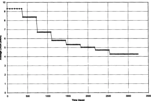
Figure 2.2 Average Linear Heat Generation Rate for the Manzel Test Case. ... . 38
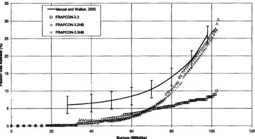
Figure 2.3 Fission Gas Release for Different Versions of FRAPCON Based on the Manzel Test C ase ... 39
Figure 2.4 Linear Heat Generation Rate for Original and Updated FRAPCON I&EC with Sintered Annular Pellets... 41
Figure 2.5 Average Fuel Temperature for Original and Updated FRAPCON I&EC with Sintered A nnular Pellets... 4 1 Figure 2.6 Outer Gap Conductance for Original and Updated FRAPCON I&EC with Sintered A nnular Pellets... 42
Figure 2.7 Inner Gap Conductance for Original and Updated FRAPCON I&EC with Sintered Annular Pellets... 42
Figure 2.8 Fission Gas Release Fraction Predicted by Original and Updated FRAPCON I&EC w ith Sintered Annular Pellets. ... 43
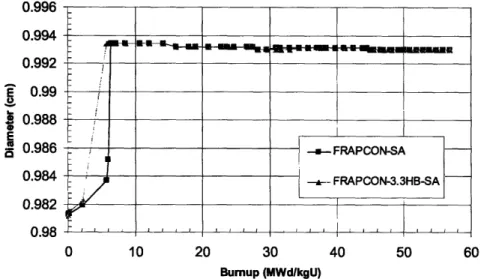
Figure 2.9 Outer Cladding Inner Diameter Predicted by Original and Updated FRAPCON I&EC w ith Sintered A nnular Pellets. ... 43
Figure 2.10 Inner Cladding Inner Diameter Predicted by Original and Updated FRAPCON I&EC with Sintered Annular Pellets. ... 44
Figure 2.11 Average Fuel Temperature Predicted by Original and Updated FRAPCON I&EC w ith V IPA C Fuel ... ... 46
Figure 2.12 Fission Gas Release Fraction Predicted by Original and Updated FRAPCON I&EC w ith V IPA C Fuel ... ... 46
Figure 2.13 Fuel Outer Diameter Predicted by Original and Updated FRAPCON I&EC with V IPA C Fuel ... ... 47
Figure 2.14 Fuel Inner Diameter Predicted by Original and Updated FRAPCON I&EC with V IPA C Fuel ... ... 47
Figure 3.1 Thermal Conductivity of Un-irradiated SiC Composites as a Function of Temperature. ... 53
Figure 3.2 Un-irradiated SiC Composites with High Thermal Conductivity as a Function of Temperature [Yam ada et al., 2004]. ... 53
Figure 3.3 Thermal Conductivity of SiC Composites Irradiated at Room Temperature ... 54
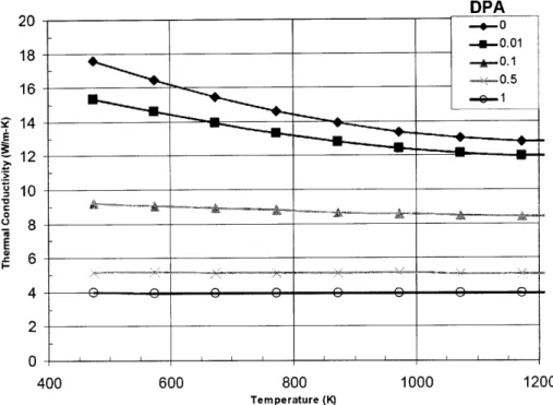
Figure 3.4 SiC Composite Thermal Conductivity Predicted by FRAPCON as a Function of DPA and Temperature ... 55
Figure 3.5 SiC Composite (Hi-Nicalon Type-S with CVI) Thermal Conductivity as a Function of DPA and Temperature [Youngblood, 2004] ... ... 55
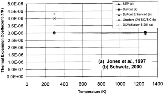
Figure 3.6 Through Thickness Thermal Expansion Coefficient versus Temperature for SiC Com posites ... ... 56
Figure 3.7 In-plane Thermal Expansion Coefficient versus Temperature for SiC Composites... 57
Figure 3.8 Temperature Dependence of the Irradiation-Induced Swelling of SiC Composites with Hi-Nicalon Fibers [Ishihara et al., 2002]. ... ... 59
Figure 3.9 Young's Modulus for Un-irradiated SiC Composites versus Temperature... 60
Figure 3.10 Young's Modulus of SiC Composites as a Function of DPA. ... 61
Figure 3.11 Yield Strength of SiC Composites versus Temperature ... 62
Figure 3.12 SiC Composite Ultimate Tensile Strength as a Function of DPA ... 63
Figure 4.1 Average LHGR for the Constant Power Test Case ... ... 68
Figure 4.2 Average Burnup for the Constant Power Test Case ... ... 68
Figure 4.3 Cladding Thermal Conductivity during the Constant Power Test Case ... 69
Figure 4.4 Cladding Temperature at the Cladding Outer Diameter (OD) and Cladding Inner Diameter (ID) for the Constant Power Test Case. ... ... 70
Figure 4.5 Fuel Temperature at the Fuel Outer Diameter (OD) and Fuel Centerline for the Constant Pow er Test Case. ... 70
Figure 4.6 Fuel-Cladding Radial Gap Width for the Constant Power Test Case... . 71
Figure 4.7 Fractional Fission Gas Release for the Constant Power Test Case. ... 72
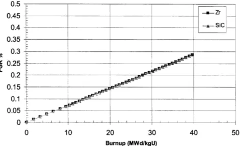
Figure 4.8 Average LHGR for Zircaloy (Zr) and SiC Composite (SiC) Clad Fuel Rods for Manzel Test Case ... 73
Figure 4.9 Average Burnup for Manzel Test Case ... 73
Figure 4.10 Cladding Thermal Conductivity for Manzel Test Case ... ... . 74
Figure 4.11 Radial Fuel-Cladding Gap Width for Manzel Test Case ... ... 75
Figure 4.12 Cladding Inner Diameter for Manzel Test Case ... ... 75
Figure 4.13 Cladding Inner and Outer Diameter Temperatures for Manzel Test Case. ... 76
Figure 4.14 Fuel Temperature for Zircaloy and SiC fuel rods at Fuel Outer Diameter and Centerline for M anzel Test Case... 77
Figure 4.15 Radial Fuel-Cladding Gap Thermal Conductance for Manzel Test Case. ... 77
Figure 4.17 Fuel Rod Free Gas Pressure for Manzel Test Case. ... ... 79
Figure 4.18 Thermal Conductivity Based on Different Thermal Conductivity Model Parameters. ... 81
Figure 4.19 Cladding Temperature Based on Different Thermal Conductivity Model Parameters. ... 82
Figure 4.20 Fuel Temperature Based on Different Thermal Conductivity Model Parameters ... 83
Figure 4.21 Fission Gas Release Based on Different Thermal Conductivity Model Parameters. ... 83
Figure 4.22 Internal Free Gas Pressure Based on Different Thermal Conductivity Model Param eters... ... 84
Figure 4.23 Radial Fuel-Cladding Gap Conductance Based on Different Thermal Conductivity Model Parameters. ... 85
Figure 4.24 Radial Fuel-Cladding Gap Width Based on Different Thermal Conductivity Model Parameters... ... 85
Figure 4.25 Radial Fuel-Cladding Gap Width for Different Thermal Expansion Models. ... 87
Figure 4.26 Fractional Fission Gas Release for Different Thermal Expansion Models. ... 87
Figure 4.27 Radial Fuel-Cladding Gap Width for Different Irradiation Swelling Models ... 89
Figure 4.28 Fuel Temperature for Different Irradiation Swelling Models. ... 90
Figure 4.29 Fractional Fission Gas Release for Different Irradiation Swelling Models... 90
Figure 4.30 Cladding Inner Diameter for Different Young's Modulus Models ... 92
Figure 4.31 Radial Fuel-Cladding Gap Width for Different Young's Modulus Models ... 93
Figure 4.32 Internal Free Gas Pressure for Different Initial Fill Gas Pressures. ... 95
Figure 4.33 Fuel Temperature for Different Initial Fill Gas Pressures ... ... 96
Figure 4.34 Fuel-Cladding Gap Thermal Conductance for Different Initial Fill Gas Pressures... 96
Figure 4.35 Fractional Fission Gas Release for Different Initial Fill Gas Pressures. ... 97
Figure 4.36 Fuel Temperature for Solid and Annular Fuel Pellets ... ... 98
Figure 4.37 Radial Fuel-Cladding Gap for Solid and Annular Fuel Pellets. ... . 99
Figure 4.38 Fractional Fission Gas Release for Solid and Annular Fuel Pellets ... 100
Figure 4.39 Internal Free Gas Pressure for Fuel Rods with Solid and Annular Fuel Pellets ... 100
Figure 4.40 Fuel Temperature for Zircaloy-Clad Fuel Rods with UO2 and MOX Fuel, and SiC-Clad Fuel Rods with MOX Fuel. ... 102
Figure 4.41 Fractional Fission Gas Release from UO2 and MOX Fuel Pins with Zr and SiC Cladding... 103
Figure 4.42 Internal Free Gas Pressure for UO2 and MOX Fuel Rods with Zr and SiC Cladding... 104
Figure 5.1 I&EC VIPAC Annular Fuel Rod with SiC Duplex Cladding ... 107
Figure 5.2 Average Fuel Temperature of I&EC VIPAC Annular Fuel Rods with Zircaloy and SiC Cladding... 108
Figure 5.3 Average Cladding Temperature of Zr- and SiC-clad I&EC VIPAC Annular Fuel Rods... 109
Figure 5.5 Average Power of I&EC VIPAC Annular Fuel High Burnup Case with Zircaloy and SiC Cladding ... 111 Figure 5.6 Average Burnup of I&EC VIPAC Annular Fuel High Burnup Case with Zircaloy and
SiC Cladding ... 111 Figure 5.7 Average Fuel Temperature of I&EC VIPAC Annular Fuel High Burnup Case with
Zircaloy and SiC Cladding... 112 Figure 5.8 Fractional Fission Gas Release of I&EC VIPAC Annular Fuel High Burnup Case with
Zircaloy and SiC Cladding... 112 Figure 5.9 Internal Free Gas Pressure of I&EC VIPAC Annular Fuel High Burnup Case with
Zircaloy and SiC Cladding... 113 Figure 5.10 Average Cladding Strain of I&EC VIPAC Annular Fuel High Burnup Case with
Zircaloy and SiC Cladding... 114 Figure 5.11 I&EC Sintered Annular Fuel Rod with SiC Duplex Cladding ... ... 115 Figure 5.12 Average Fuel Temperature for I&EC Sintered Annular Pellet Fuel Rods with Zircaloy
and SiC Cladding. ... 116
Figure 5.13 Cladding Temperature for I&EC Sintered Annular Pellet Fuel Rods with Zircaloy and
SiC Cladding ... 117
Figure 5.14 Average Cladding Strain of Sintered Annular Pellet Fuel Rods with Zircaloy and SiC
Cladding... 118
Figure 5.15 Internal Free Gas Pressure for I&EC Sintered Annular Pellet Fuel Rods with Zircaloy
and SiC Cladding. ... 118
Figure 5.16 Gap Conductance for I&EC Sintered Annular Pellet Fuel Rods with Zircaloy and SiC
Cladding... 119
Figure 5.17 Average Burnup of I&EC Sintered Annular Fuel High Burnup Case with Zircaloy
and SiC Cladding at 150% Power Density. ... 120 Figure 5.18 Average Fuel Temperature of I&EC Sintered Annular Fuel High Burnup Case with
Zircaloy and SiC Cladding... 121 Figure 5.19 Fractional Fission Gas Release of I&EC Sintered Annular Fuel High Burnup Case
w ith Zircaloy and SiC Cladding... 122 Figure 5.20 Internal Free Gas Pressure of I&EC Sintered Annular Fuel High Burnup Case with
Zircaloy and SiC Cladding... 122 Figure 5.21 Average Cladding Strain of I&EC Sintered Annular Fuel High Burnup Case with
Zircaloy and SiC Cladding... 123 Figure 6.1 Pre-irradiation I&EC Annular Fuel Irradiation Capsule 4 (left) with Cross-Section
Schem atic... . 125 Figure 6.2 Top View of Collimator and Detector Setup with Hot Box ... 131
Figure 6.4 I&EC Annular Fuel Capsule in Hot Box at Beginning of Gamma Counting... 132
Figure 6.5 Net Counts per Second from the Cs-137 Absolute Calibration Source... 133
Figure 6.6 I&EC Annular Fuel Capsule's Cover Gas Tube being Cut in MITR-II Core Tank ... 134
Figure 6.7 I&EC Annular Fuel Capsule 3 after Irradiation ... 135
Figure 6.8 I&EC Annular Fuel Capsule 4 after Irradiation. ... 136
Figure 6.9 Exterior of Hot Box during Capsule Counting ... 138
Figure 6.10 View of Hot Box Interior from Right Viewing Port during Capsule Counting... 138
Figure 6.11 Net Count Rate for the Zr-95 Peak at 724 keV for Capsule 3 and Capsule 4. ... 139
Figure 6.12 Net Count Rate of Dominant Radionuclides in Capsule 3 with to-scale Fuel Rod C ross-Section. ... 140
Figure 6.13 Net Count Rate of Dominant Radionuclides in Capsule 4 with to-scale Fuel Rod Cross-Section . ... 140
Figure 6.14 Ratio of the Cs-134 to the Cs-137 Net Count Rate in the Fuel Region (position 2.5 to 9.5), Corrected for D ecay... 144
Figure 6.15 Net Count Rate of Kr-85 (514 keV) for each Capsule ... 146
Figure 7.1 Top View of MITR-II Core Showing SiC Loop In-Core Irradiation Location B-3 ... 150
Figure 7.2 Axially-Averaged Neutron Flux in Loop In-Core Section Calculated by MCNP... 150
Figure 7.3 Anticipated Neutron Flux Profile for SiC Irradiation... 151
Figure 7.4 Sample Module Containing Three Layers with Three SiC Tubes in Each Layer. ... 152
Figure 7.5 In-Core Section of SiC Irradiation Loop with Four Modules. ... 153
Figure 7.6 Coolant Flow Pattern in SiC Irradiation Loop [Chitelain, 2000]... 154
Figure 7.7 SiC Irradiation In-Core Loop in Position B-3 in Simplified MITR-II Core Tank... 155
Figure 7.8 Coolant Control System for SiC Irradiaition Facility [Chitelain, 2000]... 156
Figure 7.9 Hot Cell for SiC Sample PIE... 162
Figure 7.10 Partially Assembled 2-Layer Module with Three SiC Samples, Flow Shroud, and H olding Platters Shown. ... 164
Figure 7.11 SiC Irradiation Loop Installed in the MITR-II Core. ... 165
Figure 7.12 Thimble and Autoclave Top Seated in Reactor Lid Prior to Insulation and Shielding ... 166
Figure 7.13 SiC Irradiation Facility Pressure and Water Chemistry Monitors ... 167
LIST OF TABLES
Table 2.1 Initial Fuel and Cladding Properties for the Manzel Test Case ... 37
Table 2.2 Initial Fuel and Cladding Properties for the SA-100 Test Case... 40
Table 2.3 Initial Fuel and Cladding Properties for the VA-100 Test Case ... 45
Table 3.1 Design Ranges for SiC Property Models ... 49
Table 3.2 SiC Fibers of Interest [Ichikawa and Ishikawa, 2000 and Osborne et al., 1998]... 50
Table 3.3 SiC Monolith Materials of Interest [Snead et al., 2005] ... ... 50
Table 4.1 Thermal Conductivity Sensitivity Conditions ... 80
Table 4.2 Thermal Expansion Sensitivity Conditions ... 86
Table 4.3 Irradiation Swelling Sensitivity Conditions... 88
Table 4.4 Young's Modulus Sensitivity Conditions... 91
Table 4.5 Initial Fill Gas Pressure Options ... ... 94
Table 4.6 Fuel Pellet Central Void Dimensions. ... 98
Table 4.7 MOX Fuel Actinide Vector ... 101
Table 6.1 1 MeV Photon Attenuation Calculation Material Properties ... 128
Table 6.2 Exposure Rate for a Single Capsule through Various Thicknesses of Lead for 1 MeV Photons . ... 129
Table 6.3 Estimated Activity of Major Isotopes in Fuel... 141
Table 6.4 Estimated Activity of Cs-137 in Fuel. ... 142
Table 6.5 Constants Used in Bumup Calculations [Chang, 2005]. ... 143
Table 6.6 Calculated Burnup from Cs-137 Activity ... 143
Table 6.7 Calculated Burnup from Cesium Ratio... 145
Table 6.8 Fuel Rod Geometry Based on Fabrication Report [AECL, 2003]... 147
Table 6.9 Data for Fission Gas Release Estimate Based on Kr-85... 147
Table 7.1 Elemental Loading the SiC Irradiation Loop... ... 159
Table 7.2 Activities for SiC Irradiation Loop after 1620 Hours (90 EFPD with 75% Capacity Factor) and 3 D ays of Cooling ... 159
Table A. 1 Description of SiC Irradiation Loop Specimens ... 184
Table A.2 Location of Loop Specimens (Numbered from Bottom of Core) ... 184
Table A.3 Pre-Irradiation Specimen Dimensions ... 185
Table A.4 Pre-Irradiation Specimen Weights... 186
Table B. 1 Neutron Activation Analysis Sample Description ... 187
Table B.2 Elements Identified in Sample Cl ... ... 187
Table B.3 Elements Identified in Sample G2 ... 188
NOMENCLATURE
AFCI Advanced Fuel Cycle Initiative
CVD Carbon Vapor Deposition
CVI Carbon Vapor Infiltration
DNBR Departure from Nucleate Boiling Ratio
DPA Displacements per Atom
EFPD Effective Full Power Days
I&EC Internally- and Externally-Cooled
LHGR Linear Heat Generation Rate
LWR Light Water Reactor
MCNP Monte Carlo N-Particle Code
MITR MIT Nuclear Reactor
MOX Mixed Oxide
ORIGEN Oak Ridge Isotope Generation Code
PIE Post-Irradiation Examination
PIP Polymer Impregnation Pyrolysis
PWR Pressurized Water Reactor
SiC Silicon Carbide
TD Theoretical Density
TRU Transuranic
1.
Introduction
1.1
Background
Transuranic (TRU) elements are responsible for a significant fraction of the long-term radiation and decay heat of commercial spent reactor fuel, and some TRU isotopes, such as Pu-239, represent a proliferation risk. It has been demonstrated that it is possible to destroy these TRU isotopes efficiently in a thermal spectrum, such as that in a light water reactor (LWR), and therefore there is interest in developing transmutation fuels for use in current-generation power reactors [Shwageraus et al., 2003].
Transmutation fuels replace some or all of the UO2 in the fuel rod with plutonium and other TRU from spent fuel, enabling these isotopes to be fissioned in the reactor. Since all operating commercial reactors in the United States are LWRs utilizing traditional pin-type fuel rods, the performance of this fuel is critical to the transmutation performance. These rods consist of a stack of sintered UO2 pellets encased in a thin zirconium-based cladding. While performance has been continually improved since their inception, this solid pin design has remained basically unchanged. Recent research at MIT has investigated possible approaches for significantly improving the power density supported by LWR fuel rods by altering their geometry or by using different cladding materials [Yuan et al., 2004]. These changes are applicable to both traditional UO2 fuel as well as
the transmutation fuels under development.
The primary purpose of these changes is to allow the fuel rods to be run at a higher power density and to withstand higher burnup. A higher power density increases the rate at which power is produced (more fissions per unit time), within a given fuel volume, whereas the increased burnup allows a larger fraction of the fuel in the rod to be consumed before it is discharged. In addition, these changes will maintain or improve upon fuel rod performance and safety margins during both normal operation and accident scenarios.
The improved design could allow power uprating of existing LWR cores with minimal core modification, and increase the maximum allowable discharge burnup. This is beneficial for the traditional fuel management in once-through fuel cycles since it increases the efficiency of uranium usage and increases power output. Since less uranium fuel volume is required for the same energy output, the volume of waste is reduced. The design improvements also benefit transmutation since increasing power density increases the rate that TRU is destroyed and higher burnup enables more TRU to be transmuted before the fuel is reprocessed. For both traditional and transmutation fuels, higher burnup significantly reduces the amount of plutonium in the spent fuel for a given amount of energy generation, and enhances the proliferation resistance by increasing the fraction of Pu-238 in the plutonium [Zhiwen et al., 2005].
To increase the maximum power density, the fuel rods need to be redesigned. For example, they can be changed from the traditional pin design to an annular geometry with internal and external cooling, which increases the cooled surface area for the same volume of fuel. Research has been done to optimize the geometry, materials, and manufacturing of this annular fuel and recently prototype annular rods were irradiated in the MIT reactor. This scoping analysis sought to verify the computer modeling of the thermal hydraulic and irradiation behavior of the rods. In addition, because the annular rods used vibration-packed UO2 fuel grains (VIPAC) instead of traditional sintered pellets, the in-core irradiation also provided an opportunity to examine the VIPAC fuel irradiation behavior [Kazimi et al., 2005]. VIPAC is an attractive technology because it
increases the ease of manufacturing; a simple manufacturing process is especially important for fuels with significant amounts of TRU because of its high activity and spontaneous fission rate.
One of the tasks of this project is the post-irradiation examination of the annular fuel rods. This experimental analysis is critical because it will allow measurement of the burnup, fission gas release, and structure of the fuel, which will help to validate the
In addition to the geometry changes, a new cladding material could allow increased burnup and power density by improving heat transfer and the thermal, chemical, and mechanical stability of the rod. Such improvements in behavior during normal and transient operation would allow power density and burnup limits set by safety analysis to be increased.
Silicon carbide (SiC) has been proposed as such a replacement for the traditional Zircaloy cladding, as it has beneficial features like reasonable thermal conductivity, a higher melting temperature, does not experience creep like a metal, and does not react exothermically with water. In order to determine the viability of SiC cladding it will be necessary to perform computer modeling of its in-core behavior, and ultimately to conduct irradiation testing of prototype cladding designs for verification of the effects of radiation damage to its mechanical and thermal properties.
1.2
Objectives and Scope
The overall objective is to examine some of the innovative ideas for increasing the power density and burnup limits for LWR fuels, in particular by using ceramic cladding for internally- and externally-cooled annular fuel containing U0 2 and mixed oxide (MOX)
fuel. This objective will be accomplished through four tasks.
The first task is modeling of the thermal and mechanical behavior of the SiC cladding using a computer code. This requires accurate prediction of the relevant properties of SiC cladding given different temperature, stress, and irradiation conditions. Next, these properties will be used to create a model that appropriately predicts the behavior of a SiC-clad fuel rod under realistic LWR operating conditions. The behavior of this rod can then be compared to a Zircaloy-clad rod under identical circumstances. Finally, this modeling will be used to explore the benefits and limitations of SiC cladding by quantifying important behavior, measuring the sensitivity of the cladding behavior to property variations, and optimizing the geometry.
The second task is an assessment of the attempt to improve the performance of the proposed annular fuel design by using SiC cladding. This first involves combining the SiC cladding model with a previously developed internally- and externally-cooled annular fuel rod model [Yuan et al., 2004]. Next, the performance of this SiC-clad annular fuel rod will be compared to a Zr-clad annular rod under identical conditions in order to understand what additional advantages the ceramic provides, and both rod types will be studied in combination with sintered annular fuel pellets and the VIPAC fuel form. In addition, because transmutation fuels would contain a large amount of plutonium, a MOX fuel model will be incorporated. Modeling MOX fuel allows a study of the effect of different fuel compositions on fuel rod behavior.
The third task is to conduct the post irradiation examination of the prototype annular UO2 fuel rods. The goals of the examination are to obtain estimates for the average burnup of the VIPAC fuel, the fraction of fission gas released, and the distribution of fuel particles within the rod using facilities available at the MIT Nuclear Reactor Laboratory. This information will be compared to the predictions of the computer models in order to qualify their precision. It will also expand understanding of the behavior of the annular rod design and the VIPAC fuel under conditions similar to that of a LWR core.
The final task is preparation for the in-core irradiation of SiC cladding samples in the MIT reactor (MITR-II). This preparation involves the design and construction of the in-core test rig, and preparation of the procedures necessary for loading, on-line monitoring, and removal of the rig from the core. This irradiation will allow multiple cladding samples of different shapes and construction to be irradiated at known temperatures and fluxes. The test rig also allows samples to be replaced mid-run without major disassembly of the rig. Finally, the test rig must meet all reactor safety requirements and not interfere with possible concurrent in-core experiments. The post-irradiation examination of the SiC specimens is not within the scope of this work.
1.3 Internally- and Externally-Cooled Annular Fuel
It is desirable to reduce the fuel temperature in order to reduce fission gas release, swelling, and increase the margin to overheating. Because the highest temperature in a fuel rod occurs in the center of the pellet, previous investigations in the U.S. [Caner and Dugan, 2000] and in Russia [Bibilashvili et al., 1994] have looked at creating annular
fuel pellets. These sintered pellets are formed with a central void, usually 10-50 volume percent, which removes the temperature peaking at the center of the pellet.
This central void is still limiting, however, since heat can still only be removed through the outer surface of the pellet and it creates a channel for fuel and debris relocation. Recent work at MIT has resulted in the design of an internally- and externally-cooled (I&EC) annular fuel rod, which creates an open channel through the center of the fuel rod to allow coolant flow and the removal of heat. Because the goal of this investigation was a fuel rod that could be used in existing LWRs, the rod configuration was constrained by the Westinghouse PWR fuel assembly dimensions, and a 13x13 fuel rod array, shown in Figure 1.1, was chosen as the base design [Kazimi, 2002].
Figure 1.1 Conceptual Design for 13x13 I&EC Annular Fuel PWR Assembly [Kazimi, 2002].
7Tý77r- 77r 71V_
7ý
W, 'tie' ý!ii +io
"o, AL Mh 1i;EW 4 0 7,1119, ij .7 ;20 Tr, 0 4, 7, _4 + 40
4
Pr
""14
+7 +7hL
1.3.1 Sintered Pellets
Similar to the annular pellets for solid fuel rods discussed above, one proposed approach to the I&EC annular fuel rods is through pressed and sintered annular pellets. Such a manufacturing approach has been considered previously in France with the Advanced Plutonium Assembly, which used large I&EC plutonium-fueled rods in place of four U02
pins in a 17x17 PWR assembly [Puill et al., 2001].
Sintered annular pellets are able to achieve the same density as standard sintered pellets, but are more difficult to manufacture with the appropriate tolerances on the outer and inner surfaces. In addition, asymmetry of the pellet-cladding gaps is a point of concern [Puill 2001]. Such asymmetries may occur due to thermal expansion of the fuel, which will tend to close the outer fuel-cladding gap first. This closure will cause the gap conductance to be much larger on the fuel's outer surface, and correspondingly the heat flux through the fuel rod's outer diameter will increase. A higher heat flux will have safety implications, as it reduces the Departure from Nucleate Boiling Ratio (DNBR). DNBR has an NRC regulated minimum, and that would be a limiting factor for the sintered annular fuel's performance in a PWR. Similarly, in Boiling Water Reactor there would be concerns over exceeding channel heat flux limits. Possible methods for alleviating this problem are increasing the initial outer radial gap, decreasing the thermal conductivity of the outer gap, adding highly conductive bonding filler in place of the gap cover gas, or decreasing the inner gap [Yuan et al., 2004].
The recent MIT design for I&EC annular fuel with sintered annular pellets, shown in Figure 1.2, was analyzed for use in a PWR in 13x13 assemblies [Yuan et al., 2004]. In a collaboration between Gamma Engineering Corporation, MIT, and Westinghouse Electric Corporation, these pellets were successfully manufactured by Westinghouse in 2003. These pellets, which are shown in Figure 1.3, were made to demonstrate the mechanical and economic feasibility of creating sintered UO2 pellets, and that the manufacturing was within the scope of current pellet fabrication facilities [Kazimi, 2003].
- Coolant
Outer Cladding
- Fuel
Inner Cladding
L
Figure 1.2 Schematic of I&EC Sintered Annular Pellet Fuel for a 13x13 Assembly.
Figure 1.3 Sintered Annular Pellets Produced by Westinghouse [Kazimi, 2003].
1.3.2 VIPAC Fuel
An alternative to the use of sintered pellets is Vibration Packed (VIPAC) fuel, which consists of fuel grains that are compacted into the fuel rod via vibration and compressive
22 L 14.1 mm 9.9 mm
I
Fimpacts. These grains are obtained by crushing and milling sintered fuel forms, then sorting the resulting shards by diameter. This technique has been used to create MOX and UO2 fuel for irradiation in the U.S. and Russia [Yuan et al., 2004].
The main benefits of VIPAC fuel are easy loading of the annular geometry, elimination of the fuel-cladding gap, and simple fuel manufacturing. The simple manufacturing of the VIPAC grains and straightforward process for loading the fuel rod are key advantages over the sintered pellets, and these factors could translate into an economic incentive for using VIPAC fuel. Since there is no fuel-cladding gap the initial thermal resistance at that interface is significantly reduced [Yuan et al., 2004]. This addresses the asymmetry
problem found with sintered pellets while at the same time lowering the average fuel temperature. In addition, VIPAC fuel irradiation have shown less chemical and mechanical interaction with the inside surface of the cladding than pelletized fuel.
The difficulty with VIPAC is achieving acceptable fuel smear densities, at least equivalent to those of sintered pellets. A high smear density is important both to maximize fuel loading and to achieve the highest possible thermal conductance in the fuel. VIPAC fabrication techniques have achieved up to 86% of theoretical density (TD), compared to the standard sintered pellet density of 94% TD [Icenhour, 2005]. It is possible that the density could be increased further through selection of different grain sizes, grain mixing ratios, packing steps, and additives such as powdered uranium metal.
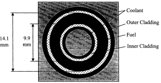
The I&EC annular fuel rod designed by MIT with sintered annular pellets was also analyzed for use with VIPAC fuel. The inner and outer dimensions of the rod are the same, however because of the nature of VIPAC fuel there are no gaps between the fuel and cladding, as shown in Figure 1.4 [Yuan et al., 2004].
In addition, in 2003 a four-foot long I&EC VIPAC annular fuel rod was manufactured by the Atomic Energy of Canada, Ltd. (AECL) Chalk River Laboratory to the MIT-specified annulus dimensions. By using two size categories of fuel granules (25-53 tm and
250-595 Rm), and packing by impacting the fuel rod and using an annular tamping rod, AECL was able to achieve up to 76.9% TD [Kazimi, 2003].
9.77
7
CoolantOuter Cladding SFuel
Inner Cladding
Figure 1.4 Schematic of I&EC VIPAC Annular Fuel for a 13x13 Assembly [Kazimi, 2003].
1.4
MIT
I&EC
Annular Fuel Irradiation Program
As part of a US Department of Energy sponsored program, six I&EC fuel rods, shown in Figure 1.5, were manufactured by AECL for irradiation in the MIT reactor. These fuel rods contained 5% enriched UO2 in VIPAC grains, and three had uranium metal powder added to increase the smear density. The purpose of this irradiation was to investigate the behavior of the fuel as a result of the annular geometry and VIPAC fuel form. In particular, the goals were to examine the temperature difference between the inner and outer cladding surfaces, as well as the temperature behavior with burnup. Other parameters of interest were fission gas release, fuel swelling and relocation, and average burnup [Kazimi, 2003].
14.2
Figure 1.5 I&EC VIPAC Annular Fuel Rods Manufactured for Irradiation in MITR-II [Kazimi, 2003].
The geometry of these fuel rods was slightly different than the 13x13 design specified earlier by MIT because of manufacturing constraints and the need to enclose the cladding in a secondary containment before irradiation. The fuel rods were 3.94" long with a 2.76" active fuel length; the fuel region had an OD of 1.17" and an ID of 0.93". By using two grain sizes (25-53 pm and 250-500 ipm) AECL was able to achieve a smear density of up to 82% TD in the U0 2-only fuel rods, and 87.5% TD in the fuel rods with 15% uranium
metal powder added [AECL, 2003].
Two of the UOz2-only fuel rods were irradiated in the core of the MIT reactor from March
to September of 2004 inside of specially designed I&EC aluminum capsules [Kazimi et
aL, 2004]. The top of the capsule assembly is shown in Figure 1.6. The inside and outside
surfaces of these capsules were instrumented with thermocouples to allow the temperature at the inner and outer cladding to be monitored during irradiation, and cover gas from inside of the aluminum capsule was periodically sampled to measure any fission gasses escaping from weld imperfections.
After irradiation, the two annular fuel rods were removed from the core and placed in underwater storage for one year to allow for cooling and decay. In August of 2005, both
irradiated capsules were removed from storage and underwent a post-irradiation examination at MIT. The design, results, and an analysis of this examination is presented in Chapter 6 of this report. In the future, these capsules may be sent to the Idaho National Laboratory's Hot Fuel Examination Facility for further analysis.
Top of Capsule
AssemblyFigure 1.6 I&EC VIPAC Annular Fuel Irradiation Rig Installed in the Core of the MITR-II.
1.5
Silicon Carbide
1.5.1 Background
of SiC
Development
Silicon Carbide (SiC) has been considered for use in high-temperature, high-radiation environments since first investigated by Rovner and Hopkins in 1976 as a first wall material for fusion reactors [Rovner, 1976]. It has also been considered as structural coating on fuel kernels for high temperature gas-cooled reactors for many years [CEGA, 1993], and as an inert matrix for fuel pellets [Alkan et al., 2001]. Pure SiC has attractive properties when compared to available metal alloys, primarily as a consequence of relative stability up to tens of Displacements per Atom (DPA). Unlike metals, it
experiences minimal swelling or loss of strength, does not creep below 10000C, and is
less prone to degrading chemical interactions. Importantly for fission energy applications, it also has a small neutron absorption cross section [Hasegawa, 2000].
SiC can be manufactured using several different processes, although the one of most interest for nuclear applications is Carbon Vapor Deposition (CVD) because it is able to produce a high-purity SiC layer. This process involves reacting silicon and carbon compounds, often in gaseous form, with hydrogen at high temperatures. This has been used to coat fuel particles, but can also be used to create bulk solids [Brook, 1991].
A significant issue when considering SiC as a moderate temperature (<10000C) structural
material is primarily its brittle fracture characteristic. The small elastic yield is significant when it must operate up to PWR core temperatures and pressures, around 3000C and 15
MPa, since it cannot dissipate accumulating external stresses (from irradiation swelling and thermal expansion of other materials, or fission gas release) through creep. A second difficulty is the degradation of SiC thermal conductivity with DPA. Although stoichiometric SiC has excellent thermal conductivity, after only one DPA the thermal conductivity will saturate at a much lower value due to accumulation of microstructure defects, typically to 2-8 W/m-K. This is significantly less than other common reactor materials exposed to similar conditions, such as Zircaloy [PNNL, 2002].
1.5.2 SiC Composites
In order to create large SiC structures, as well as to increase bend strength, SiC/SiC composite materials were developed. The composite consists of SiC fibers arranged parallel or braided, and then bonded with an SiC matrix. There are several fabrication techniques, depending on the method of matrix infiltration, but the two of most interest in this work are Carbon Vapor Infiltration (CVI) and Polymer Impregnation Pyrolysis (PIP) [Hasegawa, 2000]; both methods create a high purity SiC matrix between the fibers. The fibers provide large tensile strength and the ability to withstand localized fractures without completely failing the structure. The matrix provides stability while allowing the
fibers some ability to flex, meaning the composite will have significantly more yield perpendicular to the fiber axis than a solid structure.
The mechanical benefits of the composite are balanced by the creation of a less dense, porous structure, with a lower thermal conductivity. In addition, because the fibers generally contain impurities of free silicon and carbon, as well as nitrogen or oxygen additives, there tends to be a difference in irradiation swelling behavior between the matrix and the fibers that must be considered.
1.5.3
Advanced Clad Project
A collaboration organized by Gamma Engineering, and involving the MIT Center for Advanced Nuclear Energy Systems (CANES), is investigating the use of SiC as a fuel rod cladding material for Light Water Reactors (LWRs). This concept involves the use of a duplex design, which combines an SiC monolith and an SiC/SiC woven composite to create a cladding tube where the SiC duplex replaces the traditional Zircaloy cladding. An example of this duplex design is shown in Figure 1.7. The monolith provides for containment of fission gasses while the composite provides additional strength and protection of the monolith surface.
Coolant
Composite -Monolith
Fuel Space
There is interest in using SiC as a cladding material because it maintains strength even at high temperature (>10000C), has a small neutron absorption cross section, and in general
has good property performance to high DPA. It is expected that these characteristics will allow higher allowable cladding temperatures, and in particular, better transient and accident performance, and power uprates. In addition, the stability of its physical properties under extended irradiation and ability to contain larger internal pressures without creeping outward may enable the extension of the fuel rod's maximum allowable burnup.
The MIT part of the current collaboration involves modeling the behavior of SiC duplex cladding in LWRs using several computer codes, including the steady-state thermo-mechanical code FRAPCON, which is covered in Chapters 2 through 5 of this report. Other modeling work is to include transient and accident analysis using the codes FRAPTRAN and RELAP. In addition to the computer modeling, this project also includes the irradiation of various duplex cladding designs for at least three months in the MIT reactor under PWR conditions. After irradiation, the samples will undergo PIE both at MIT and at Oak Ridge National Laboratory. The purpose and design of this experiment is covered in more detail in Chapter 7 of this report.
1.6 FRAPCON Computer Code
The FRAPCON-3 steady state fuel rod modeling code was developed by the Pacific Northwest National Laboratory for use by the U.S. Nuclear Regulatory Commission in evaluation of LWR fuel rod behavior up to a burnup of 65 MWd/kgU. The code models the fuel and cladding of a single fuel rod, and calculates temperature distributions, stress and strain, fission gas release, cladding oxidation, and other physical behavior as a function of an input power history and core conditions [Berna et al., 1997].
FRAPCON is a deterministic code that relies on a combination of theoretical and empirical relations to determine the properties of the fuel rod only at discreet time steps, where the step interval is generally days to weeks. The code's predictions have been
benchmarked against experimental irradiation data, and it is expected to provide characteristic results for limited variations on traditional fuel rod design and operating conditions.
The use of an I&EC annular fuel rod geometry, VIPAC fuel, and SiC cladding, as investigated in this report, are all outside the scope of FRAPCON's original programming. Adding these features requires modification of the source code and has resulted in the creation of several distinct versions of FRAPCON at MIT. The modifications made to FRAPCON to incorporate SiC cladding are discussed in Chapter 3 of this report. Pertinent modifications made by previous researchers, and other official updates to the source code are discussed in Chapter 2.
1.7 Thesis Organization
This thesis covers both theoretical and experimental investigation relevant to the development of a new fuel design for fission reactors: the development of computer based SiC-clad fuel rod models for evaluation, and the design and evaluation of
experimental studies of the proposed fuel, fuel rod geometry, and cladding materials.
In Chapter 2, the general structure and solution routine of the FRAPCON steady-state fuel rod modeling code is discussed. Several major modifications to the code relevant to this project are also discussed, involving the implementation of I&EC annular fuel, VIPAC fuel, MOX fuel, and improved modeling at high burnup.
In Chapter 3, new FRAPCON routines that were created to model SiC cladding are discussed and compared to the available data. These changes include all of the material properties, with particular focus on thermal conductivity, thermal expansion, and irradiation swelling.
In Chapter 4, the newly created version of FRAPCON with SiC cladding is used to model fuel rods under typical reactor operating conditions and conditions of special interest,
such as high power density and high burnup. In addition, possible avenues for enhancing the performance of the SiC-clad fuel rod are explored, such as variation of fill gas pressure, use of annular pellets, different assembly configurations, and MOX fuel.
In Chapter 5, the SiC cladding models are applied to the I&EC annular fuel version of
FRAPCON in order to investigate the benefits of this combined construction. There is a discussion and analysis of the modeling of both VIPAC fuel and sintered annular pellets.
In Chapter 6, the post-irradiation examination of prototype I&EC annular fuel rods is discussed. This section covers both the design of the PIE station at the MIT reactor and results of the examination of two irradiated fuel rods. The fuel rods were examined visually and were analyzed using gamma spectroscopy to infer fuel distribution and swelling, burnup, and fission gas release.
In Chapter 7, the design and construction of a test rig for the irradiation of SiC cladding samples is discussed. This rig is designed to allow irradiation of multiple samples of un-fueled cladding in PWR pressure, temperature, and chemistry conditions in the core of the MIT reactor. In addition, groups of samples can be removed from the rig in MIT hot cell facilities after irradiation, and the rig returned to the core with some new samples for continued irradiation.
In Chapter 8, the results of this thesis research will be summarized and possibilities for future investigation of the topics covered in this work will be proposed.
2. Fuel Rod Modeling in FRAPCON
2.1
Code Structure
The FRAPCON computer code couples the thermal and mechanical behavior of a single LWR fuel pin during irradiation at a specified linear heat generation rate under specified core conditions. It arrives at a solution through the use of empirical models for fuel and cladding properties, which feed into theoretical calculations of temperature distributions and physical (mechanical, chemical, and nuclear) responses. It then iterates this process to find the steady-state behavior of the fuel rod after a given segment of irradiation history [Berna et al., 1997]. A simplified version of the FRAPCON solution scheme is shown in Figure 2.1. V = "L-L, F• .5; P. w .r
Figure 2.1 Simplified Flow Chart of FRAPCON-3 Iterative Solution Scheme [Berna et al., 1997].
The required code inputs include fuel and cladding geometry, fuel enrichment, primary coolant conditions, and the listing of the neutron flux, linear heat generation rate, and axial power shape at each time step. The user also inputs a mesh sizing for FRAPCON's finite difference calculations of pellet heat conduction and fission gas release. FRAPCON takes these inputs and then uses a pre-defined set of relations for UO2 or MOX pellets and Zircaloy cladding to calculate physical properties during each iteration. In order to specify new material behavior, the subroutines controlling the desired property must be modified and the code re-compiled.
2.1.1
Implementation of
I&EC
Annular
Fuel
The FRAPCON-3 source code was modified by Yi Yuan [Yuan et al., 2004] to model I&EC annular fuel rods with Zircaloy cladding, and both sintered annular pellets and VIPAC fuel. This modified code was then used to analyze the behavior of the new fuel rod geometry and fuel forms, and to conduct parametric studies on the fuel rod design.
The changes that were made to the source code can be generalized into seven areas: * Radial fuel temperature profile calculation
* Fuel-cladding interaction model * Heat flux and coolant flow models * Fission gas release
* Fuel dimensional changes * Radial power profile * Cladding conditions
These modifications were focused on adding parameters for the simultaneous calculation of the inner and outer cladding and fuel behavior where previously only the outer surface was of concern, as well as new physical models to account for the increased moderation
2.1.2
Implementation of VIPAC Fuel
As a part of the implementation of the I&EC annular fuel models in FRAPCON, models for VIPAC fuel were added [Yuan et al., 2004]. In some ways, the VIPAC fuel models resemble sintered pellets operating in a closed fuel-cladding gap regime, with some differences based on the interaction of individual fuel grains. The VIPAC fuel model differs from the solid sintered pellets and solid annular sintered pellets in the same basic ways: the inner and outer fuel-cladding gaps are always closed, fuel radial relocation is removed, thermal expansion serves to contract the inner annulus as well as expand the outer diameter, and fission gas released is enhanced in proportion to total exposed grain surface area.
2.1.3
Implementation of Updated
UO
2and MOX Fuel Models
The organization responsible for the development of FRAPCON, Pacific Northwest National Laboratory, issued an update for FRAPCON-3 in May 2005 [Lanning et al., 2005]. This update, FRAPCON-3.3, included several changes relevant to this work
including updates to models for the properties of urania and MOX fuel. Because these changes increase the accuracy of the code's predictions, it was desirable to incorporate these changes into the versions of FRAPCON created for I&EC annular fuel with sintered pellets and VIPAC fuel.
The changes to the urania fuel models incorporate relations based on newly available experimental data. Both the urania thermal conductivity and fission gas release models were modified to better reflect data at higher temperatures and burnup (>2500 K and 30 MWd/kgU).
The update also contains changes to many of the MOX fuel models, which are receiving attention due to renewed interest in MOX use in LWRs. A significant amount of new data has become available worldwide from MOX irradiations, and the target MOX plutonium composition has decreased. To reflect this new information, the following models were updated: MOX thermal conductivity, fission gas release and He production, swelling and
thermal expansion, and radial power profile [Lanning et al., 2005]. 34
In addition to these model-specific changes, varieties of other small changes were made to correct errors or oversights in the previous release version of FRAPCON.
2.1.4
Implementation of High-Burnup Fission Gas Release Model
The recommended maximum burnup in FRAPCON, based on the data used for the creation of the fuel thermal and mechanical properties and fission gas release, is 62 MWd/kgU, which provides sufficient coverage of expected burnup in current generation LWR fuel pins [Lanning et al., 2005]. However, in this investigation there is interest in extension of the maximum burnup because of the combination SiC cladding's good radiation tolerance and the improved performance of I&EC annular fuel (i.e. lower fuel and cladding temperatures). It is thought that these factors could allow LWRs to achieve burnup up to 100 MWd/kgU.
An investigation into the possibility of using FRAPCON to model fuel rods into this very high burnup regime was performed by Yun Long at MIT [Long, 2002]. In the course of this research, fission gas release was identified as a driving parameter for fuel rod performance at high burnup; however, the current FRAPCON predictions did not agree well with measured data at very high burnup. As a result, several modifications were made to the urania fission gas release model to conform better to the current phenomenological understanding of fission gas release, and replicate experimental release data at very high burnup more accurately.
The new models explicitly treat the buildup of fission gasses in the rim region of the pellets, and threshold release caused by fission gas saturation at high burnup. In particular, the threshold release model replaces the standard athermal model, which
2.2 Benchmarking of Updates
2.2.1
FRAPCON-3.3 with High Burnup Modifications
As the first part of this investigation, Yun Long's changes to FRAPCON concerning fission gas release in UO2 at high burnup were incorporated into the latest release of FRAPCON, version 3.3. This new version, hereafter referred to as FRAPCON-3.3HB, was used as the basis for the development of all other FRAPCON versions used in this project.
In order to evaluate the performance of this new code, an input case was developed based on data from an experimental campaign measuring fission gas release up to high burnup. A recent study of the effect of high burnup on U02 was conducted by Manzel and Walker
in Germany [Manzel and Walker, 2000]. In this study, a group of similar fuel rods was tracked in Siemens PWRs. In order to reach extended burnup these rods were removed from spent assemblies and placed into a fresh assembly, then irradiated for another series of burnup cycles. During each refueling, some rods were removed from this cycle and destructively examined for microstructure changes and fission gas release. In this way, some fuel rods were irradiated to a maximum burnup of over 100 MWd/kgU. From this study, fission gas release data is available for average fuel rod burnup between 19 and 98 MWd/kgU.
Data given by Manzel and Walker concerning linear heat generation rate, enrichment, irradiation cycles, and fuel rod construction was incorporated into a FRAPCON input file. However, insufficient data on certain factors, such as coolant characteristics and neutron flux, were given to completely specify the required input, and therefore additional data had to be obtained from other sources. The missing information was incorporated from FRAPCON input data supplied by Pacific Northwest National Laboratory on a reactor similar to the Siemens PWRs, the Oconee plant, a Babcock and Wilcox PWR utilizing 15x15 assemblies with fuel rod dimensions nearly identical to the Siemens design. The fuel and cladding properties used in this input file, hereafter referred
to as the "Manzel" test case, are given in Table 2.1. The axial power shape is the Oconee mid-life profile, which has a peaking factor of 1.12.
Table 2.1 Initial Fuel and Cladding Properties for the Manzel Test Case.
Dimension Units Value
Cladding outside diameter cm (in.) 1.09 (4.30x10-'
Cladding inside diameter cm (in.) 9.58x10- (3.77x10⁻¹
Cladding thickness mm (in.) 6.73x10- (2.65 x10⁻²)
Clad arithmetic mean roughness mm (mils) 5.00x10 (1.97 x10⁻²)
Diametral gap thickness mm (mils) 2.54x10- (10.0)
Fuel pellet diameter cm (in.) 9.32xl0-1 (3.67x10-l)
Fuel stack height m (ft.) 3.58 (11.8)
U-235 enrichment at% in U 3.85
Fuel rod pitch cm (in.) 1.42 (5.60x10⁻¹)
Channel equivalent diameter cm (in.) 1.27 (4.99x10-)
The Manzel input case was run in three versions of FRAPCON for comparison: the most recently released version (FRAPCON-3.3), the version created by Yun Long incorporating a new high burnup fission gas release model (FRAPCON-3.2HB), and the new version created for this study that combines the new fission gas release model with release version 3.3 (FRAPCON-3.3HB). The average rod linear heat generation rate at each time step for this input is given in Figure 2.2.
![Figure 1.5 I&EC VIPAC Annular Fuel Rods Manufactured for Irradiation in MITR-II [Kazimi, 2003].](https://thumb-eu.123doks.com/thumbv2/123doknet/14107318.466200/25.918.218.710.97.423/figure-vipac-annular-fuel-rods-manufactured-irradiation-kazimi.webp)
![Figure 3.8 Temperature Dependence of the Irradiation-Induced Swelling of SiC Composites with Hi-Nicalon Fibers [Ishihara et al., 2002].](https://thumb-eu.123doks.com/thumbv2/123doknet/14107318.466200/59.918.210.721.108.423/temperature-dependence-irradiation-induced-swelling-composites-nicalon-ishihara.webp)