Publisher’s version / Version de l'éditeur:
Vous avez des questions? Nous pouvons vous aider. Pour communiquer directement avec un auteur, consultez la première page de la revue dans laquelle son article a été publié afin de trouver ses coordonnées. Si vous n’arrivez pas à les repérer, communiquez avec nous à [email protected].
Questions? Contact the NRC Publications Archive team at
[email protected]. If you wish to email the authors directly, please see the first page of the publication for their contact information.
https://publications-cnrc.canada.ca/fra/droits
L’accès à ce site Web et l’utilisation de son contenu sont assujettis aux conditions présentées dans le site LISEZ CES CONDITIONS ATTENTIVEMENT AVANT D’UTILISER CE SITE WEB.
Technical Report; no. CHC-TR-081, 2011-05-01
READ THESE TERMS AND CONDITIONS CAREFULLY BEFORE USING THIS WEBSITE.
https://nrc-publications.canada.ca/eng/copyright
NRC Publications Archive Record / Notice des Archives des publications du CNRC :
https://nrc-publications.canada.ca/eng/view/object/?id=3162e119-721c-4e69-a8d9-d07cc944aa4a https://publications-cnrc.canada.ca/fra/voir/objet/?id=3162e119-721c-4e69-a8d9-d07cc944aa4a
NRC Publications Archive
Archives des publications du CNRC
For the publisher’s version, please access the DOI link below./ Pour consulter la version de l’éditeur, utilisez le lien DOI ci-dessous.
https://doi.org/10.4224/20171298
Access and use of this website and the material on it are subject to the Terms and Conditions set forth at
Deposition of granular solids Sayed, Mohamed; Dabros, Tadek
DEPOSITION OF GRANULAR SOLIDS
Mohamed Sayed and Tadek Dabros
DRAFT
Technical Report CHC-TR-081
DEPOSITION OF GRANULAR SOLIDS
Mohamed Sayed
Canadian Hydraulics Centre
National Research Council of Canada Ottawa, Ontario Tadek Dabros NRCanENERGY Devon, Alberta Technical Report CHC-TR-081 April 2011
ABSTRACT
The present work employs the proposed formulations of the solids stresses by Savage (2011) to examine the deposition of dry granular materials. The aim is to examine the performance of the expressions of the solids stresses, and to provide insights into the behavior of the problem of deposition of tailings. The simulations are also intended to examine the role of boundary conditions, and to provide means for testing the accuracy and efficiency of numerical solution approaches. The simulations consider single-phase solids flow. They provide a basis for future extension to simulating two-phase solids-liquid deposition.
The results show that a stable heap can be formed by using the stress formulation of Savage (2011) together with both no-slip and Coulomb friction boundary conditions at the base of the heap. The results determine the influence of the angle of internal friction and the friction coefficient at the base on the resulting shape of the heap. Distributions of the solids volume fraction and pressures within the heap are presented. The present results form a basis for subsequent development of two-phase, solids-liquid simulations.
ii CHC-TR-081
TABLE OF CONTENTS
1. INTRODUCTION ... 1
2. THE GOVERNING EQUATIONS ... 2
2.1 Conservation of Mass and Linear Momentum ... 2
2.2 Constitutive Equations ... 2
3. THE NUMERICAL APPROACH ... 3
4. SET-UP OF THE NUMERICAL SIMULATIONS ... 3
5. DEPOSITION OVER A NO-SLIP BASE ... 4
6. DEPOSITION OVER A FRICTIONAL BASE ... 10
7. CONCLUSION ... 14
8. ACKNOWLEDGEMENTS ... 15
TABLE OF FIGURES
Figure 1: The set-up for the numerical simulations. ... 4 Figure 2: Plots of particle positions showing the evolution of the heap geometry; no-slip boundary conditions and φ= 25o. ... 6 Figure 3: Distribution of the solids volume fraction; no-slip boundary conditions and φ= 25o. ... 7 Figure 4: Distribution of the pressure (mean normal stress); no-slip boundary conditions and φ= 25o. ... 7 Figure 5: Plots of heap geometry for different values of φ; no-slip boundary conditions. . 9 Figure 6: Plot of the side slope of the heap versus the angle of internal friction, no-slip
boundary conditions. ... 10 Figure 7: Heap geometry for different values of the friction coefficient between the base and the bulk material, angle of internal friction φ= 25o. ... 12 Figure 8: Solids volume fraction corresponding to Coulomb friction boundary conditions at the base, φ= 25o and µ= 0.1. ... 13 Figure 9: Pressures corresponding to Coulomb friction boundary conditions at the base,
φ= 25o
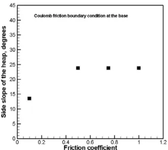
and µ= 0.1. ... 13 Figure 10: Plot of the slope of the heap versus the friction coefficient at the base, φ= 25o.
Deposition of Granular Solids
1.
INTRODUCTION
The work report here is part of a project aimed at modeling solid-liquid flows of oil sands tailings. The emphasis of the project is on developing appropriate constitutive models for the solids phase that are able to simulate a number of flow situations. The project also involves development of governing equations for solid-liquid mixtures, and solutions that employ the COMSOL software platform. The present work employs the proposed formulations of the solids stresses by Savage (2011) to examine the deposition of dry granular materials. The aim is to examine the performance of the expressions of the solids stresses, and to provide insights into the behavior of the problem of deposition of tailings. The simulations are also intended to examine the role of boundary conditions, and to provide means for testing the accuracy and efficiency of numerical solution approaches. The simulations consider only single-phase solids flow. They provide a basis for future extension to simulating two-phase solids-liquid deposition.
Deposition of tailings is of particular industrial interest. The problem also pauses difficulties to most numerical simulations techniques. Reproducing the often observed stable heap geometries of the deposited materials has proved to be a challenging problem. We note that the present investigation addresses the case of bulk material falling under gravity to form a heap over a horizontal or inclined plane. This case is somewhat different from the release of a rectangular block of material already resting on a horizontal plane.
Early treatment of the deposition problem employed discrete element simulations. Baxter et al (1997) were able to simulate stable heaps using a two-dimensional discrete model. Those simulations produced stable heap geometries and predicted stress distributions within the heap. Those simulations required placing a fixed layer of particles at the base of the heaps. The discrete element approach has additional limitations concerning properties of the bulk material, and the number of particles that can be used. More recent work by Christakis et al. (2006) employed a continuum formulation based on a Drucker-Prager plastic yield function and a finite element solution. Two-dimensional simulations of filling of bins produced stable heaps.
Although the literature on deposition of granular materials is relatively limited, there is a much larger volume of investigations of the closely related problem of collapsing rectangle (or cylinder) of bulk material. That problem is addressed within the current project by Savage (2011).
The present work uses the formulation of the granular stress of Savage (2011) to examine the two-dimensional deposition of dry granular materials. The roles of material properties and boundary conditions are explored.
2.
THE GOVERNING EQUATIONS
2.1 Conservation of Mass and Linear Momentum
We consider here single phase flow of bulk granular materials.
(
)
0 = ⋅ ∇ + ρ ν v ν ρ s s t d d (1) g σ v ρ ν ν ρs s t d d + ⋅ ∇ − = ⎥ ⎦ ⎤ ⎢ ⎣ ⎡ (2)where ν is volume fraction of the solids, ρs is the solids density, v is the velocity, σ is the
stress tensor, and g is the gravitational acceleration.
2.2 Constitutive Equations
The stress-strain relationship that satisfy a Mohr-Coulomb yield criterion can be expressed as
(
)
ij ij kk ij ij p p A ν ε ε δ δ σ ⎟ − ⎠ ⎞ ⎜ ⎝ ⎛ − Δ = • • 2 1 , 2 (3)where σij is the stress tensor,
•
ij
ε is the strain rate tensor, and p is the pressure. The strain rate Δ is given by
• • • • • • • • • • • + + + ⎟ ⎠ ⎞ ⎜ ⎝ ⎛ − + ⎟ ⎠ ⎞ ⎜ ⎝ ⎛ − + ⎟ ⎠ ⎞ ⎜ ⎝ ⎛ − = = Δ 12 23 13 2 33 11 2 33 22 2 22 11 2 2 3 1 3 1 3 1 ε ε ε ε ε ε ε ε ε ε εij ij (4)
The function A is given by ϕ
sin
p
A= (5)
where φ is the traditional angle of internal friction.
Equations 3 to 5 follow the formulation of Savage (2011). Because of the present solution method, we require an additional equation to link the pressure p to the solids volume fraction ν. The following expression is usually used
ν ν ν ν − − = max min C p (6)
where νmin is a minimum solids volume fraction below which the pressure vanishes, and
νmax is the solids volume fraction that corresponds to maximum packing. The constant C
can be taken as C = k ρs gL, where L is a length scale for the problem under
consideration. The non-dimensional parameter k would represent a stiffness of the bulk material.
3.
THE NUMERICAL APPROACH
The present solution employs a hybrid Lagrangian-Eulerian approach. The momentum and constitutive equations are solved on a fixed grid. A finite difference explicit solution is used over a staggered rectangular grid. The scalars are defined over the cells, while the vectors are defined over the nodes. Advection is modeled using a Particle-In-Cell (PIC) method, where an ensemble of particles represents the bulk granular material. The particles may be viewed as moving nodes that hold the various material attributes and variables such as the solids volume fraction and the velocity. The particles are advected in a Lagrangian manner.
Solution of the momentum and constitutive equations gives the strain rates, stresses, accelerations and velocities over the grid. Those variables are then mapped to the particles. The continuity equation is then solved over each particle in order to update the solids volume fraction. The particles are next advected to new positions. For a detailed discussion of the PIC approach, see for example Sulsky et al (1995).
The present approach makes it possible to use several types of boundary conditions. Stress-free boundaries do not require special treatment. At the base of the heap, velocity boundary conditions could be used. A no-slip conditions sets the velocity to zero. A full slip condition sets the normal velocity to zero (directed towards the wall) to zero. But the tangential velocity and normal velocity directed away from the wall can take any value. A Coulomb friction boundary condition can also be used, and is more representative of the physics of the problem.
4.
SET-UP OF THE NUMERICAL SIMULATIONS
The bulk material was supplied at a constant rate from a bin placed 0.5 m above a horizontal plane as shown in Figure 1. An aperture of 0.1 m controlled the flow of the solids, which fall to form a heap over the horizontal plane. The wall boundaries of the bin were treated using a full-slip boundary condition; i.e. frictionless walls. The vertical velocity at the exit from the bin varied from approximately 0.9 m/s for φ= 25o to 0.8 m/s for = 55o.
After a time interval of 2 s, the aperture was closed. This was done by applying a full-slip boundary condition along the entire bottom of the bin. The simulations usually covered sufficiently long durations, after closing of the aperture, in order to allow the heap to reach a stable condition (zero velocities over the entire heap).
The boundary conditions for the horizontal base were treated in a number of ways. One series of tests used a no-slip condition, which represents very high friction. Another series used a Coulomb friction condition. Several values of the friction coefficient were tested.
In addition to the horizontal plane which served as a base for the heap, a cursory test was done using an inclined plane.
Figure 1: The set-up for the numerical simulations.
5.
DEPOSITION OVER A NO-SLIP BASE
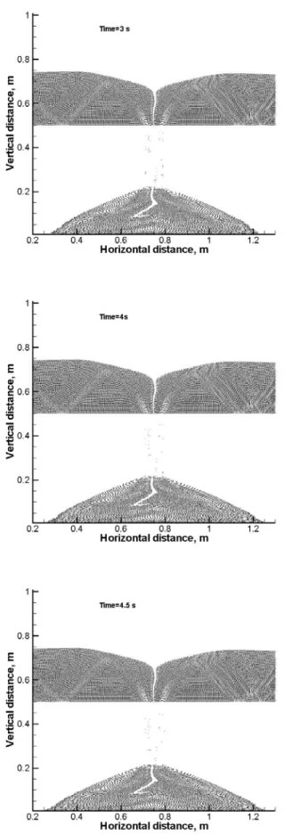
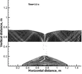
The results of one test case corresponding to φ= 25o is presented here at some detail in order to illustrate the process of heap formation. Plots of the particles (used in PIC advection) are shown in Figure 2 at time intervals of 1s, 2s, 3s, 4s and 4.5 s. Note that the aperture that feeds the bulk material is closed after 2s. The plots show how the heap grows and reaches a stable shape. Slope angle of the sides of the heap is 24o. This slope angle is very close to the angle of internal friction, φ.
Figure 2: Plots of particle positions showing the evolution of the heap geometry; no-slip boundary conditions and φ= 25o.
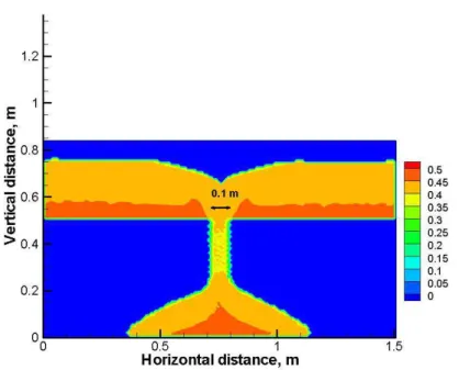
The distributions of the resulting solids volume fraction and pressure (mean normal stress) at the end of the simulation are shown in Figure 3 and Figure 4, respectively. The solids volume fraction, as expected, increases with depth. The pressures are also higher at the base of the heap. The pressure distribution along the base is uniform over a relatively wide length of the base. It does not peak below the apex of the heap. It is also difficult to detect any peaks off the centerline of the heap as sometimes noticed in experimental measurements and discrete element simulations (Baxter et al., 1997).
Figure 3: Distribution of the solids volume fraction; no-slip boundary conditions and φ= 25o .
The influence of the angle of internal friction, φ on the resulting heap is illustrated in Figure 5 by plotting particle positions for values of φ = 30o, 40o, 50o, and 55o. All heaps became stable immediately after the feeding of the bulk material stopped. The larger values of φ obviously produces heaps with steeper side slopes.
φ = 30o
.
φ = 40o
φ = 50o
.
φ = 55o
.
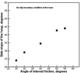
Figure 6: Plot of the side slope of the heap versus the angle of internal friction, no-slip boundary conditions.
The side slope of the heap is plotted versus the angle of internal friction in Figure 6. The value of the slope is usually slightly smaller than the angle of internal friction. By comparison, Christakis et al. (2006) reported much larger differences between the side slope of the heap ad the angle of internal friction. Their tests simulated filling of a bin. The bulk material was laterally confined at the base conditions under the heap, which would be similar to the present no-slip condition. Christakis et al. (2006) reported that for φ= 30o
and 45o, the corresponding slopes were 14o and 20o, respectively; i.e. the slope was close to half the value of the angle of internal friction.
6.
DEPOSITION OVER A FRICTIONAL BASE
The boundary conditions at the base may have a significant influence on the shape of the heap. Many applications do not correspond to the idealized no-slip condition that was explored in the preceding section of this report. Instead, the base of the heap may have some friction with a slip velocity taking place. In this section we consider a series of simulation that employed a Coulomb friction condition at the base of the heap.
The boundary conditions set the downward velocity component normal to the base to zero. A normal velocity directed away from the base (upwards) may exit. The tangential component of the velocity remains non-zero. A tangential force acts along the base opposite to the direction of the tangential velocity. The friction coefficient is defined here as μ =sin−1δ , where δ is the friction angle between the bulk material and the base. Simulations were done for the case of φ= 25o. The following values of the friction coefficient were tested: µ= 0.1, 0.5, 0.75 and 1.0. In all cases a stable heap formed. The resulting heap geometries are shown in Figure 7. The results show that stable heaps formed using the Coulomb friction boundary conditions. The distributions of the solids volume fraction and pressures for the case of µ= 0.1 are shown in Figure 8 and Figure 9,
respectively. Those distributions display similar patterns to those obtained for the case of n-slip boundary conditions at the base.
The resulting side slope of the heap is plotted versus the friction coefficient in Figure 10. Clearly the slope is limited by the value of φ. The maximum slope attained is approximately 24o, which is very close to the value of φ= 25o.
Friction coefficient, µ= 0.1.
Friction coefficient, µ= 0.75.
Friction coefficient, µ= 1.0.
Figure 7: Heap geometry for different values of the friction coefficient between the base and the bulk material, angle of internal friction φ= 25o.
Figure 8: Solids volume fraction corresponding to Coulomb friction boundary conditions at the base, φ= 25o
and µ= 0.1.
Figure 9: Pressures corresponding to Coulomb friction boundary conditions at the base, φ= 25o and µ= 0.1.
Figure 10: Plot of the slope of the heap versus the friction coefficient at the base, φ= 25o.
7.
CONCLUSION
Numerical simulations examined the deposition of dry granular material under gravity and the formation of stable heaps. The aim is to test the performance of the frictional stress formulation of Savage (2011) and to explore the process of granular heap formation. The simulations focused on single-phase solids flow. This is a first step towards the development of two-phase, liquid-solids solutions.
The present simulations examined the role of boundary conditions at the base of the granular heap. Past studies (Baxter et al., 1997; and Christakis et al., 2006) had to employ a no-slip condition at the base. Although a Coulomb friction boundary condition may appear physically more appropriate in many situations, it usually caused difficulties to numerical simulations. The present tests have used both a no-slip and Coulomb friction boundary conditions.
The results show that a stable heap can be formed by using the stress formulation of Savage (2011) together with both no-slip and Coulomb friction boundary conditions. For the no-slip boundary condition, the side slope of the heap increased with increasing value of the angle of internal friction, φ. The slope was only slightly smaller than the value of φ. For Coulomb friction, the side slope increased with increasing value of φ up to a maximum value. That maximum value is limited by the value of the coefficient of friction between the bulk solids and the base. Increasing the value of φ beyond that limit did not increase the slope of the heap.
Distributions of solids volume fraction and pressures were presented for some of the test cases. Both solids volume fraction and pressure increase from the surface of the heap towards the base. The pressure distribution along the base of the heap usually showed a maximum value that spanned a relatively wide portion of the base around the centre of
the heap. There was no evidence of the formation of two peaks that are offset from the centerline.
Subsequent work will employ a two-phase formulation to examine the effects of solids-liquid interaction. Further comparisons with solution obtained using COMSOL software and validation against experimental data will also be carried out.
8.
ACKNOWLEDGEMENTS
The financial support of the Program on Energy Research and Development (PERD) is gratefully acknowledged.
9.
REFERENCES
Baxter, J., Tuzun, U., and Burnell, J. (1997). “Granular dynamics simulations of tw-dimensional heap formation,” Physical Review E, Vol. 55, No. 3, pp. 3546-3554.
Christakis, N., Chappelle, P., and Patel, M.K. (2006). “Analysis and modeling of heaping behavior of granular mixtures within a computational mechanics framework,” Advanced Powder Technology, Vol. 17, No. 4, pp. 383-398.
Savage, S.B. (2011). “Granular material rheology for use in COMSOL modeling,” Report submitted to NRCanENERGY, Devon, Alberta, March 14, 2011.
Sulsky, D., Zhou, S-J., Schreyer, H.L. (1995). “Application of a particle-in-cell method to solid mechanics,” Computer Physics Communications, Vol. 87, pp. 236-252.