Publisher’s version / Version de l'éditeur:
Vous avez des questions? Nous pouvons vous aider. Pour communiquer directement avec un auteur, consultez la
première page de la revue dans laquelle son article a été publié afin de trouver ses coordonnées. Si vous n’arrivez pas à les repérer, communiquez avec nous à [email protected].
Questions? Contact the NRC Publications Archive team at
[email protected]. If you wish to email the authors directly, please see the first page of the publication for their contact information.
https://publications-cnrc.canada.ca/fra/droits
L’accès à ce site Web et l’utilisation de son contenu sont assujettis aux conditions présentées dans le site LISEZ CES CONDITIONS ATTENTIVEMENT AVANT D’UTILISER CE SITE WEB.
Medical Image Computing and Computer-Assisted Intervention – MICCAI 2011:
14th International Conference, Toronto, Canada, September 18-22, 2011,
Proceedings, Part I, Lecture Notes in Computer Science; no. 6891, pp. 323-330,
2011-10
READ THESE TERMS AND CONDITIONS CAREFULLY BEFORE USING THIS WEBSITE. https://nrc-publications.canada.ca/eng/copyright
NRC Publications Archive Record / Notice des Archives des publications du CNRC :
https://nrc-publications.canada.ca/eng/view/object/?id=ed339668-26bb-4efc-8301-69f0f5e3fc54
https://publications-cnrc.canada.ca/fra/voir/objet/?id=ed339668-26bb-4efc-8301-69f0f5e3fc54
NRC Publications Archive
Archives des publications du CNRC
For the publisher’s version, please access the DOI link below./ Pour consulter la version de l’éditeur, utilisez le lien DOI ci-dessous.
https://doi.org/10.1007/978-3-642-23623-5_41
Access and use of this website and the material on it are subject to the Terms and Conditions set forth at
Layered surface fluid simulation for surgical training
Abstract. We present a novel approach to fluid simulation over com-plex dynamic geometry designed for the specific context of virtual surgery simulation. The method combines a surface-based fluid simulation model with a multi-layer depth peeling representation to allow realistic yet ef-ficient simulation of bleeding on complex surfaces undergoing geometry and topology modifications. Our implementation allows for fast fluid propagation and accumulation over the entire scene, and runs on the GPU at a constant low cost that is independent of the amount of blood in the scene. The proposed bleeding simulation is integrated in a com-plete simulator for brain tumor resection, where trainees have to manage blood aspiration and tissue/vessel cauterization while they perform vir-tual surgery tasks.
Keywords: visual simulation, GPU, fluid simulation, bleeding, cauter-ization, aspiration, depth peeling, surgery, neurosurgery.
1
Introduction
The key challenge in virtual surgery simulation lies in the large amount of com-puter resources required for real-time interactive simulation of complex physics and for realistic haptic and visual feedback. This paper contributes a technique for the efficient integration of a proven and low-cost fluid simulation approach to the context of bleeding simulation for surgery, where the fluid must adapt to the constantly transforming geometry associated with the tissue simulation.
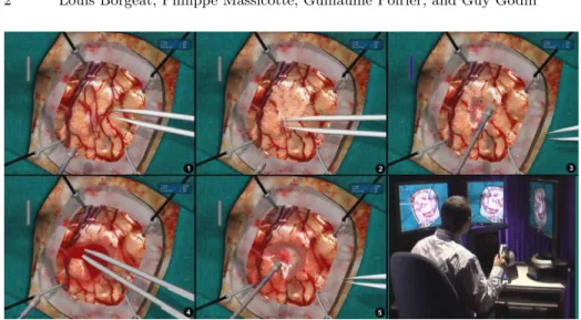
The research presented in this paper was performed in the context of the de-velopment of a complete patient-specific brain tumor resection simulator, shown in Figure 1. The simulator provides haptic feedback for two hands/tools, finite element (FE) tissue modeling and simulation with topological adaptation during resection, and realistic visual feedback including high resolution texturing and lighting, smooth cast shadows, depth of field, lens distortion, and bleeding. The simulator is currently being evaluated in hospitals for resident training.
Significant research efforts have already been targeted at fluid simulation in the context of bleeding for surgery training. Andersson [1] surveys the various fluid effects required by surgery simulation. Our specific requirement, established with clinical partners, was for a model supporting fast and realistic surface blood flow and accumulation over the entire simulated surface of the surgical zone.
2 Louis Borgeat, Philippe Massicotte, Guillaume Poirier, and Guy Godin
Fig. 1.Brain tumor resection with the Neurotouch simulator. 1. Initial brain surface. 2. After surface vessels cauterization with virtual tool. 3. Tissue aspiration. 4. Blood accumulation and cauterization. 5. Final blood aspiration, bleeding has been stopped. 6. Simulator prototype with haptic tools and stereoscopic display.
Among particle-based fluid simulation techniques, many recent contributions expand on the Smoothed Particle Hydrodynamics method [7][10][11], but such techniques were too slow for our application. Most other solutions are grid-based approaches in either 3D or 2D. In full 3D, good results have been achieved with 3D simulations using cubic interpolated propagation [13] that allows the use of a coarser simulation grid. Among 2D techniques, Basdogan [2] presents a real-time model of blood flow over soft tissues that projects a two-dimensional grid placed over the region of interest of the geometric tissue model. Kerwin [5] uses a two-dimensional Eulerian fluid simulation performed on the GPU which is integrated with a volume renderer. Numerous works build on height field (water column) methods where fluid equations are implemented in two dimensions using hydro-static pressure pipe models [4][9][12]. These methods allow for fast computation, wave-like behavior, net fluid transport, and dynamic boundary conditions, but due to their inherent 2D nature their application scope is limited. Such ap-proaches are also used with physically-based erosion simulation models [15][6]. For gaming, simpler models have also been proposed for fluid simulation on tex-tures [8]. But such methods usually rely on surface parameterizations that could not easily be maintained under major surface topology changes.
In this paper, we adapt the class of water column surface models to the case of complex and deforming/transforming scene geometries by applying them over a layered depth image version of the geometric model produced using a depth peeling approach [3]. The mesh is rendered at each frame into a stack of height maps. Then, an extended version of the GPU implementation of a grid-based fluid model proposed by Mei [6] is used to propagate blood on the surface. The
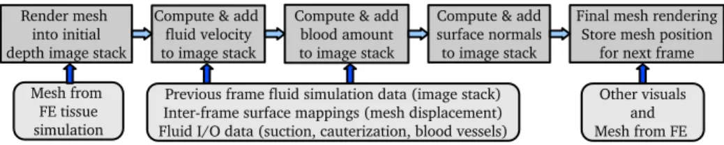
Fig. 2.Top: Processing sequence for a given frame. Bottom: input data at each step.
resulting fluid images are used when rendering the deforming geometry to add proper color, shading and elevation to the mesh. This approach brings many benefits:
– By working on images on the GPU, we achieve a fast and low-cost simulation, thus leaving most resources available for other tasks.
– Independence from the simulated mesh: by working in image space, we do not need to compute contact with the geometry, but only to be able to render it. We simply need to receive vertex offsets at each frame and a list of changed/new vertices when the topology is modified. In fact, the mesh’s physical deformation could actually be simulated on a different machine. – There is no need for a surface parameterization.
– Performance is independent of the amount of blood in the scene.
The remainder of the paper describes how a grid-based fluid model can be efficiently mapped onto a deforming and topology-changing mesh, using a water-column model for our application. The integration of the fluid simulation with the rendering as well as the performance of the method are also discussed.
2
Bleeding Simulation
In order to run an image-based fluid simulation on the deforming surface mesh computed for haptics and tissue simulation, we repeat the following sequence for each frame(Fig. 2). The mesh is first converted on the GPU into a stack of depth images rendered from a view direction aligned with gravity. We then run the modified column-based simulation on those multiple interconnected depth layers, fetching information from the image stack of the previous frame as the base for the simulation step. We finally render the mesh with the bleeding by using the simulation layers as input texture. During this process, one important challenge is to maintain a mapping between consecutive frames so that inter-frame fluid propagation takes into account mesh displacement and transformation.
Mesh to Depth Maps: The conversion of the mesh into a depth image stack is achieved by a process called depth peeling [3]: the polygonal mesh is first rendered at a chosen resolution under an orthographic view aligned with gravity and closely encompassing the entire scene. Depth/height rendered from that
4 Louis Borgeat, Philippe Massicotte, Guillaume Poirier, and Guy Godin
(a) (b) (c)
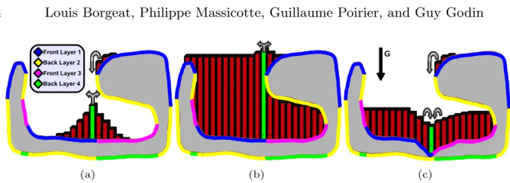
Fig. 3. Slice view of the depth peeling process and blood propagation for a simple geometric model with an overhang. Color denotes the depth layer on which a portion of the surface is represented. We illustrate 3 complex cases of blood propagation at the junction between different layers: (a) the central (green) cell gives to neighbors on the mesh, but located on different layers; (b) because of accumulation, the center cell nows gives blood to a different (higher) layer; (c) the cell receives blood from two different layers on the right.
viewpoint is stored in a floating-point GPU buffer. This process is repeated in a sequence of additional buffers, but each time all the geometry located above or at the previous height map is culled at the fragment/pixel level. We therefore end up with a decomposition of the mesh into a stack of occluding depth layers (color-coded in Fig. 3). If the 3D model is closed and not self-intersecting, the peeling process will naturally produce an alternation of front and back facing layers. In our implementation, we use the front (upward) facing layers to run the actual simulation, and keep the information of the back facing layers to insure that blood cannot accumulate beyond the upper surfaces of an enclosed area. To accelerate computations, we pack front facing layers in a single texture buffer and back facing layers in another.
Fluid Simulation: The core of the fluid simulation is similar to the work of Mei[6], but with the added difficulty that fluid must propagate properly between the different layers of the stack representing the model at a given frame and, as previously stated, between the layers associated with consecutive frames as they deform. The equations are also adapted to our application context, but the physics remains the same: cells exchange fluid with their 4 neighbors through virtual pipes, and a flow velocity, or flux, is updated at each frame based on hydrostatic pressure in the virtual pipe between the neighboring cells. Fluid propagation is computed in two rendering steps. After generating new depth layers, a first step computes a set of outflow flux (velocity) textures, setting the amount of outgoing fluid in all 4 directions and properly identifying the depth layer where the fluid must be transferred for each direction, taking into account the amount of fluid available in the cell, and the remaining available height in the target cell. Initial blood amount and flux/velocity are obtained from the last frame textures as described in the next section. Flux equations are controlled by application-specific parameters. For example, in the blood flux computation, we
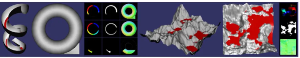
Fig. 4.Two simple models to illustrate the GPU buffers used for the fluid simulation and for the depth peeling process.Left: Depth peeling and partial simulation on a helical slide model. Buffers from left to right: Blood velocity, amount of blood, and surface normals. Right: Simulation on simple terrain model with simulation GPU buffers.
set a minimum amount of blood in a cell before it can be transferred to another one, in order to force trainees to clean tissue surfaces with the suction device.
Figure 3 illustrates different cases of inter-layer fluid exchange within a frame. As can be seen in the figure, continuous surfaces can be located on different layers of the depth image stack. When computing output flux for a cell, one target layer is selected separately in each 4 directions. However, a cell can receive fluid from the same direction from multiple neighbors located in different layers (Fig. 3(c)). The case in Figure 3(b) illustrates that, as blood accumulates, it may be sent to different layers even if the geometry does not change. When computing target layers for fluid output in one direction, we compare the height of the cell (including blood) to the height of neighboring cells (also with blood) of all layers in that direction. By integrating the maximum height (back faces) information in the comparison process, the correct target can be deterministically selected.
The second fluid simulation step computes the resulting amount of blood in a cell by gathering the flux value for each cell into a set of textures representing fluid amounts, and then modifying that value based on new bleeding and aspi-ration that may occur within that frame. The amount of new blood generated for a given layer cell is obtained from other components of the simulation. In our implementation, the FE volume structure from which the rendered surface mesh is extracted is associated through a fixed parameterization to a set of 3D volumetric textures. A high resolution texture is derived from medical imaging enhanced with synthetic data and provides vascularization information at the given location. Another 3D texture storing cauterization levels is updated locally at each frame based on the location of active cauterization tools. We also tag vertices in the mesh based on their creation or modification time, which corre-spond to the time of the last tissue cutting. All this information is combined to compute the amount of new blood at each cell. Information on the location and orientation of the blood aspiration tools is passed to the same GPU program to apply suction. Figure 4 shows the content of the flux and fluid amount textures for two simple illustrative models.
Inter-Frame Fluid Propagation: The depth image layers corresponding to consecutive simulation frames have different shapes since the rendered surface
6 Louis Borgeat, Philippe Massicotte, Guillaume Poirier, and Guy Godin
mesh undergoes continuous transformation. We therefore must establish a map-ping between these stacks to propagate the fluid and its velocity from frame to frame. To achieve this, each vertex in the geometric model retains its coordinates in the previous frame as a vertex attribute. After the peeling, we render all the vertices into a dedicated floating-point texture to store that information for the next frame.
During the fluid simulation step, a texture position and depth in the previous frame’s depth image stack is computed for each cell to allow texture fetches in the previous frame data. This position is produced on the GPU by interpolating the spatial position of the surrounding vertices in the last frame. Since the texels are generally not aligned between frames, proper sampling and filtering must be applied when fetching values from those previous frame texture stacks to avoid any aliasing effect, as well as to account for discontinuities between layers that might lead to inconsistencies in the simulation. When fetching values in the previous frame stack, all layers are sampled and depth values in the stack are used to prune out invalid samples.
Bleeding Rendering: During the final rendering, blood information is fetched from the simulation results using a custom texture filtering approach similar to the one used in inter-frame propagation, since the changing observer viewpoint does not in general match the fluid simulation viewpoint and texture resolu-tion. At that stage, we first displace the vertices on the GPU to account for the amount of blood at that location. This is mostly a simple step, but in areas at risk of numerical uncertainty errors, such as areas where the mesh is almost aligned with gravity (e.g. the left side of the surface in Fig. 3), a validation test is applied to insure that the displaced mesh is coherent with the elevation com-puted by the image-based simulation. This allows for example multiple vertices located on a vertical wall to be displaced to the same position when under the fluid surface. For meshes that are too coarse to support this approach, we have experimented with surface subdivision in a GPU geometry shader based on PN triangles [14]. This allowed the mesh displacement to be sufficiently fine, and re-duced performance only slightly more than if using the finer mesh without GPU subdivision. To deal with lighting in areas where the blood has accumulated, we compute on the GPU a set of n surface normal maps (one per front-facing layer) by taking the derivative on the n layers of depth map, again taking into account the surface connectivity between the maps. These normals progressively replace the ones computed from the mesh as a factor of blood accumulation. Such normal maps are displayed in Figure 4. In the same manner, we blend the original tissue color with the blood color as a function of the amount of fluid. The blending parameters are variables in the simulator.
3
Results and Discussion
For the results discussed here (Fig. 1), we used a stack of five depth layers, three front facing and two back facing, and a monoscopic final rendering window at
and rendering are given separately. For the 128 × 128 simulation grid used in the videos, the fluid simulation time is of 3.2 ms per frame + 1.7 ms for rendering of the global scene including the vertex displacement of a 30K polygon deformable surface mesh. With much larger 512 × 512 blood and depth textures, blood-related simulation time only increases to 9 + 4.4 = 13.4 ms. As can be seen from those numbers, the algorithm allows interactive simulation of the bleeding process at a relatively large simulation resolution. But for our application we get a bleeding that is more realistic by using smaller textures and better texture sampling/filtering at the final stage of rendering. This allows blood to propagate more quickly and at a more realistic granularity given the surgery scale (3-5 cm). Alternately, one could run two iterations of fluid simulation for each iteration of rendering. The complete visual simulation including bleeding, shadows and depth of field effects runs at a refresh rate of 60 Hz with more than 15 rendering passes per frame.
The current approach does have some limitations. Performance will diminish rapidly as the number of required layers increases, so the technique may not be practical for very intricate geometric models. This is due mainly to the fact that the custom texture filtering associated with the rendering and inter-frame texture fetches require comparison and combination of all layers in the stack. There would also be a benefit in expanding the method to be able to change the viewpoint for the depth peeling, to increase the rendering quality when observer viewpoints are too far away from the gravity axis. Finally, the vertex displacement approach used for the final rendering can lead to discontinuities in the geometric mesh in specific cases. These issues do not affect the validity of the simulation, but can lead to visual artefacts that need to be mitigated by modifying color and normal attributes on the mesh. This will happen when an enclosed pool of fluid gets filled and a part of the mesh closes on itself due to the blood displacement (e.g. Fig. 3(b)). A vertex displacement strategy also makes it difficult to assign different levels of transparency to the fluid columns in the final rendering, which may be an issue for rinsing/dilution simulation.
4
Conclusion
We have presented a method to efficiently integrate grid-based surface fluid sim-ulation to context of neuro-surgery simsim-ulation. The proposed technique allows the realistic simulation of surface bleeding, including aspiration and cauteriza-tion, over the entire operating field at a low computational cost. Future work will include the implementation of a ray-traced final render pass to allow a more complete set of visual features for the bleeding simulation, thus enabling the
8 Louis Borgeat, Philippe Massicotte, Guillaume Poirier, and Guy Godin
simulation of other important aspects of surgery. Jet bleeding and fluid falling from overhangs could be added using localized special effects or small amounts of particles at relatively low cost. Finally, the method proposed here could be adapted to other contexts, from gaming to scientific simulation.
References
1. Andersson, L.: Real-Time Fluid Dynamics for Virtual Surgery. Master’s thesis, Engineering Physics Program, Chalmers University of Technology (2005)
2. Basdogan, C., Ho, C.H., Srinivasan, M.A.: Simulation of tissue cutting and bleed-ing for laparoscopic surgery usbleed-ing auxiliary surfaces. In: Medicine Meets Virtual Reality (MMVR7) Conference. pp. 38–44. IOS Press, Amsterdam (1999)
3. Everitt, C.: Interactive order-independent transparency. White paper, NVIDIA (2001)
4. Kass, M., Miller, G.: Rapid, stable fluid dynamics for computer graphics. In: 17th Annual Conference on Computer Graphics and Interactive Techniques. pp. 49–57. SIGGRAPH ’90, ACM, New York (1990)
5. Kerwin, T., Shen, H.W., Stredney, D.: Enhancing realism of wet surfaces in tem-poral bone surgical simulation. IEEE Transactions on Visualization and Computer Graphics 15(5), 747–758 (Sept-Oct 2009)
6. Mei, X., Decaudin, P., Hu, B.G.: Fast hydraulic erosion simulation and visualization on GPU. In: 15th Pacific Conference on Computer Graphics and Applications (PG’07). pp. 47–56. IEEE Computer Society, Los Alamitos (2007)
7. M¨uller, M., Schirm, S., Teschner, M.: Interactive blood simulation for virtual surgery based on smoothed particle hydrodynamics. Technol. Health Care 12, 25– 31 (Feb 2004)
8. Myers, K.: HLSL blood shader gravity maps. White paper, NVIDIA (July 2004) 9. O’Brien, J., Hodgins, J.: Dynamic simulation of splashing fluids. In: Computer
Animation ’95. pp. 198–205. IEEE Computer Society, Washington (1995) 10. Pang, W.M., Qin, J., Chui, Y.P., Wong, T.T., Leung, K.S., Heng, P.A.: Orthopedics
surgery trainer with PPU-accelerated blood and tissue simulation. In: Ayache, N., Ourselin, S., Maeder, A. (eds.) MICCAI’07. LNCS, vol. 4792, pp. 842–849. Springer, Heidelberg (2007)
11. Qin, J., Chui, Y.P., Pang, W.M., Choi, K.S., Heng, P.A.: Learning blood man-agement in orthopedic surgery through gameplay. IEEE Computer Graphics and Applications 30(2), 45–57 (Mar-Apr 2010)
12. Raghupathi, L., Devarajan, V., Eberhart, R., Jones, D.: Simulation of bleeding during laparoscopic herniorrhaphy. In: Medicine Meets Virtual Reality (MMVR12) Conference. pp. 382–387. IOS Press, Amsterdam (2002)
13. Rianto, S., Li, L., Hartley, B.: Fluid dynamic simulation for cutting in virtual environment. In: Skala, V. (ed.) 16th International Conference in Central Europe on Computer Graphics, Visualization and Computer Vision. University of West Bohemia (2008)
14. Vlachos, A., Peters, J., Boyd, C., Mitchell, J.L.: Curved PN triangles. In: 2001 Symposium on Interactive 3D Graphics. pp. 159–166. I3D ’01, ACM, New York (2001)
15. ˇSt’ava, O., Beneˇs, B., Brisbin, M., Kˇriv´anek, J.: Interactive terrain modeling using hydraulic erosion. In: Gross, M., James, D. (eds.) 2008 Eurographics/ACM SIG-GRAPH Symposium on Computer Animation. pp. 201–210. SCA ’08, Eurographics Association, Aire-la-Ville (2008)