Publisher’s version / Version de l'éditeur:
Vous avez des questions? Nous pouvons vous aider. Pour communiquer directement avec un auteur, consultez la première page de la revue dans laquelle son article a été publié afin de trouver ses coordonnées. Si vous n’arrivez pas à les repérer, communiquez avec nous à PublicationsArchive-ArchivesPublications@nrc-cnrc.gc.ca.
Questions? Contact the NRC Publications Archive team at
PublicationsArchive-ArchivesPublications@nrc-cnrc.gc.ca. If you wish to email the authors directly, please see the first page of the publication for their contact information.
https://publications-cnrc.canada.ca/fra/droits
L’accès à ce site Web et l’utilisation de son contenu sont assujettis aux conditions présentées dans le site LISEZ CES CONDITIONS ATTENTIVEMENT AVANT D’UTILISER CE SITE WEB.
Client Report (National Research Council of Canada. Construction), 2015-06-30
READ THESE TERMS AND CONDITIONS CAREFULLY BEFORE USING THIS WEBSITE.
https://nrc-publications.canada.ca/eng/copyright
NRC Publications Archive Record / Notice des Archives des publications du CNRC : https://nrc-publications.canada.ca/eng/view/object/?id=23c77009-858a-4179-b052-e968466fc855 https://publications-cnrc.canada.ca/fra/voir/objet/?id=23c77009-858a-4179-b052-e968466fc855
NRC Publications Archive
Archives des publications du CNRC
For the publisher’s version, please access the DOI link below./ Pour consulter la version de l’éditeur, utilisez le lien DOI ci-dessous.
https://doi.org/10.4224/23002853
Access and use of this website and the material on it are subject to the Terms and Conditions set forth at
Performance evaluation of proprietary drainage components and
sheathing membranes when subjected to climate loads, task 1: wall
assembly specifications
Performance Evaluation of Proprietary
Drainage Components and Sheathing
Membranes when Subjected to Climate Loads
Task 1 — Wall Assembly Specifications
Marianne Armstrong and Bruno Di Lenardo
30 June, 2015
Table of Contents
Table of Contents...i List of Figures...iii List of Tables... v Acknowledgements...vii Summary ...ix1. Background and Introduction... 1
2. Terminology ... 2
3. Code-Compliant Reference Wall Assembly ... 2
Specifications for West Coast wall assemblies under the jurisdiction of the HPO [, ]... 4
4. Client Wall Assemblies... 8
Client A Wall Assembly Details ... 10
Client B Wall Assembly Details ... 12
Client C Wall Assembly Details ... 15
Client D Wall Assembly Details ... 17
Client E Wall Assembly Details... 19
Client F Wall Assembly Details... 23
Client G Wall Assembly Details ... 25
Client H Wall Assembly Details ... 27
Client I Wall Assembly Details... 29
Client J Wall Assembly Details... 31
Client K Wall Assembly Details ... 33
5. Summary of Wall Assemblies ... 35
List of Figures
Figure 1 – West and East coast solutions for stucco installation with capillary break... 3
Figure 2 – Code-Compliant Reference wall horizontal cross section ... 4
Figure 3 – Code-Compliant Reference wall vertical cross section ... 5
Figure 4 – Client A Wall horizontal cross section ... 10
Figure 5 – Client A Wall vertical cross section ... 11
Figure 6 – Client B Wall horizontal cross section... 12
Figure 7 – Client B Wall vertical cross section... 13
Figure 8 – Client C Wall horizontal cross section... 15
Figure 9 – Client C Wall vertical cross section... 16
Figure 10 – Client D Wall horizontal cross section... 17
Figure 11 – Client D Wall vertical cross section... 18
Figure 12 – Client E Wall horizontal cross section... 19
Figure 13 – Client E Wall vertical cross section Option 1 – Vented detail ... 20
Figure 14 – Client E Wall vertical cross section Option 2 – Ventilated detail ... 21
Figure 15 – Client F Wall horizontal cross section ... 23
Figure 16 – Client F Wall vertical cross section ... 24
Figure 18 – Client G Wall horizontal cross section... 25
Figure 19 – Client G Wall vertical cross section... 26
Figure 20 – Client H Wall horizontal cross section... 27
Figure 21 – Client H Wall vertical cross section... 28
Figure 22 – Client I Wall horizontal cross section ... 29
Figure 23 – Client I Wall vertical cross section ... 30
Figure 24 – Client J Wall horizontal cross section... 31
Figure 25 – Client J Wall vertical cross section... 32
Figure 26 – Client K Wall horizontal cross section... 33
List of Tables
Table 1 – 2010 National Building Code requirements for Capillary Breaks in Coastal areas (degree-days
< 3400 and MI > 0.9, or degree days ≥ 3400 and MI > 1.0) ... 2
Table 2 – Code-Compliant Reference Wall Component Description with Associated Rationale and NBC Requirements ... 6
Table 3 – List of Wall Assemblies and Respective Characteristic Drainage Component ... 9
Table 4 – Client A Wall description of components differing from the Benchmark Wall assembly... 10
Table 5 – Client B Wall description of components differing from the Benchmark Wall assembly ... 14
Table 6 – Client C Wall description of components differing from the Benchmark Wall assembly ... 15
Table 7 – Client D Wall description of components differing from the Benchmark Wall assembly... 17
Table 8 – Client E Wall description of components differing from the Benchmark Wall assembly ... 22
Table 9 – Client F Wall description of components differing from the Benchmark Wall assembly... 23
Table 10 – Client G Wall description of components differing from the Benchmark Wall assembly... 25
Table 11 – Client H Wall description of components differing from the Benchmark Wall assembly... 27
Table 12 – Client I Wall description of components differing from the Benchmark Wall assembly ... 29
Table 13 – Client J Wall description of components differing from the Benchmark Wall assembly ... 31
Table 14 – Client K Wall description of components differing from the Benchmark Wall assembly... 33
Acknowledgements
The report authors wish to extend their thanks to the Air Barrier Association of American (ABAA) for having managed and arranged support for this project and in particular, to Mr. Laverne Dalgleish for his highly proficient handling of all technical and non-technical issues that arose over the course of the project. As well, acknowledgment is made of project support, technical meeting participation and the many and very useful contributions made by the respective project partners, and that included:
Benjamin Obdyke Incorporated
Canadian Concrete Masonry Producers Association Cosella-Dorken
DuPont Tyvek Weatherization Systems HAL Industries Incorporated
Home Protection Office of British Columbia – HPO Keene Building Products™
GreenGuard® Building Products (formerly Pactiv Building Products) Roxul Incorporated
STO Corporation
TYPAR® Weather Protection System (Polymer Group Incorporated)
Our thanks are also extended to our colleagues within NRC-Construction for their technical support, advice, and feedback during the course of this project and who helped support the work described in this Task report, including: K. Abdulghani, S. Bundalo-Perc, S. M. Cornick, G. Ganapathy, W. Maref, T. Moore, P. Mukhopadhyaya, M. Nicholls, H. H. Saber, M.C. Swinton and D. Van Reenen.
Summary
A benchmark assembly and a series of ten client wall assemblies were developed as part of the project “Performance Evaluation of Proprietary Drainage Components and Sheathing Membranes when Subjected to Climate Loads”.
The purpose of this project was to assess the performance of wall drainage components and sheathing membranes (drainage system) in their ability to provide sufficient drainage and drying in Canadian climates with a moisture index (MI) greater than 0.9 and less than 3400 degree-days, or MI greater than 1.0 and degree days ≥ 3400 (primarily coastal areas). In these regions, the 2010 National Building Code requires a capillary break behind all Part 9 claddings. Currently, acceptable solutions* to the NBC capillary break requirement include:
(a) A drained and vented air space not less than 10 mm deep behind the cladding;
(b) An open drainage material, not less than 10 mm thick and with a cross-sectional area that is not less than 80% open, behind the cladding;
(c) A cladding loosely fastened, with an open cross section (i.e. vinyl, aluminum siding)
(d) A masonry cavity wall or masonry veneer constructed according to Section 9.20 (i.e. 25 mm vented air space)
In this project, the performance of proposed alternative solutions for the capillary break was compared through laboratory evaluation and modeling activities to the performance of a wall built to minimum1
code requirements. The proposed drainage system would be deemed an alternative solution to the capillary break requirement in the National Building Code for use with all code compliant Part 9 claddings provided it exhibits adequate moisture performance as compared to a NBC-compliant benchmark wall assembly.
In This Report — A detailed description is provided of assembly specifications, in which horizontal and
vertical cross sections are given for each wall assembly, and includes tables highlighting the differences between the client assemblies and the benchmark wall.
The specifications here-in form the basis for assessing whether the various drainage solutions provided sufficient capability for drainage and drying of wall assemblies in Canadian climates.
Performance Evaluation of Proprietary Drainage Components and
Sheathing Membranes when Subjected to Climate Loads –
Task 1 – Wall Assembly Specifications
Authored by:
Marianne Armstrong and Bruno Di Lenardo
A Report for the
AIR BARRIER ASSOCIATION OF AMERICA (ABAA)
1600 BOSTON-PROVIDENCE Highway
WAYPOLE, MA 02081
USA
ATT: Mr. Laverne Dalgleish
National Research Council Canada Ottawa ON K1A 0R6 Canada
30 June, 2015
This report may not be reproduced in whole or in part without the written consent of both the client and the National Research Council of Canada.
Performance Evaluation of Proprietary Drainage Components and
Sheathing Membranes when Subjected to Climate Loads –
Task 1 – Wall Assembly Specifications
Final Report Task 1Marianne Armstrong and Bruno Di Lenardo
1. Background and Introduction
A benchmark assembly and a series of ten client wall assemblies were developed as part of the project “Performance Evaluation of Proprietary Drainage Components and Sheathing Membranes when Subjected to Climate Loads”.
The purpose of this project was to assess the performance of wall drainage components and sheathing membranes, that comprise the second plane of protection, in their ability to provide sufficient resistance to the permeation of water at the inner boundary, and drainage and drying of assemblies subjected to Canadian climates with a moisture index (MI) greater than 0.9 and less than 3400degree-days, or MI greater than 1.0 and degree days ≥ 3400 (primarily coastal areas). In these regions, the 2010 National Building Code requires a capillary break behind all Part 9 claddings (as described in Table 1). Currently,
acceptable solutions to the NBC1capillary break requirement include:
(a) A drained and vented air space not less than 10 mm deep behind the cladding;
(b) An open drainage material, not less than 10 mm thick and with a cross-sectional area that is not less than 80% open, behind the cladding;
(c) A cladding loosely fastened, with an open cross section (i.e. vinyl, aluminum siding)
(d) A masonry cavity wall or masonry veneer constructed according to Section 9.20 (i.e. 25 mm vented air space)
In this project, the performance of proposed alternative solutions for the capillary break was compared through laboratory evaluation and modeling activities2 to the performance of a wall built to minimum
code requirements. The proposed drainage the system would be deemed an alternative solution to the capillary break requirement in the National Building Code for use with all code compliant Part 9 claddings provided it exhibits equal or better moisture performance as compared to a NBC-compliant benchmark wall assembly and adequate to ensure low risk of fungal growth on moisture susceptible materials.
1The NBC Part 9 prescribed ‘acceptable solutions’ are the minimum that must be respected for the local jurisdiction
and respective geographical area, unless they are inadequate in meeting the performance statement of art. 9.27.2.1. as relates to minimizing and preventing moisture ingress and damage. In these cases, additional measures must be taken to ensure compliance with the NBC and thereby prevent the occurrence of an unacceptable risk for the growth of fungi on moisture-susceptible materials.
TASK 1 – WALL ASSEMBLY SPECIFICATIONS
REPORT A1-000030.01 2
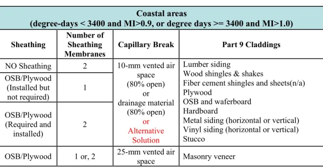
Table 1 – 2010 National Building Code requirements for Capillary Breaks in Coastal areas (degree-days < 3400 and MI > 0.9, or degree days ≥ 3400 and MI > 1.0)
2. Terminology
In this document, the term vented is used to describe an opening at the base of the cladding, whereas
ventilated refers to designed openings at the top and base of the cladding. Note that these terms refer only
to the design detail of the opening, and do not infer any amount of air circulation or water drainage behind the cladding.
This document describes assemblies in terms of specifications, and does not include as-built conditions. For example – whereas a 10 mm cavity may be specified in the specification, in reality, the process of applying stucco may potentially force stucco or building paper into the cavity, thus resulting in a clear cavity of less than 10 mm. Specific details of as-built assemblies are available for the purpose of estimating the size of the drainage cavity for the respective drainage systems is given in §2.1.2 and §3.2
of the Task 5 report on the “Characterization of Water Entry, Retention and Drainage of Components”.1
3. Code-Compliant Reference Wall Assembly
The Reference wall assemblies were developed based on minimum*1code requirements. Stucco cladding
was chosen from among the Part 9 claddings (listed in Table 1), as the “worst case scenario” for water penetration. This selection was based on previous work at NRC on the moisture management for exterior wall systems [3, 4] that demonstrated that stucco resulted in the highest moisture load behind the First
Plane of protection, due to its absorptive properties, and rain penetration at cracks.
3 Beaulieu, P. et al. (2002), Final Report from Task 8 of MEWS Project (T8-03) - Hygrothermal Response of
Exterior Wall Systems to Climate Loading: Methodology and Interpretation of Results for Stucco, EIFS, Masonry and Siding-Clad Wood-Frame Walls; Research Report, RR-118, NRC Institute for Research in Construction, 2002-11-01; 180 p.
Coastal areas
(degree-days < 3400 and MI>0.9, or degree days >= 3400 and MI>1.0)
Sheathing
Number of Sheathing Membranes
Capillary Break Part 9 Claddings
NO Sheathing 2 10-mm vented air
space (80% open) or drainage material (80% open) or Alternative Solution Lumber siding
Wood shingles & shakes
Fiber cement shingles and sheets(n/a) Plywood
OSB and waferboard Hardboard
Metal siding (horizontal or vertical) Vinyl siding (horizontal or vertical) Stucco OSB/Plywood (Installed but not required) 1 OSB/Plywood (Required and installed) 2
OSB/Plywood 1 or, 2 25-mm vented air
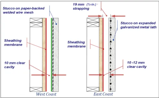
Two alternative code compliant solutions for stucco installation were considered (see Figure 1):
A solution predominantly practiced on the West Coast, is stucco application on an open welded wire metal lath with heavy paper-backing, designed to maintain a 10 mm clear cavity with 80% open between vertical furring strips;
A solution predominantly practiced on the East Coast, with expanded metal lath (no paper backing) installed on 19 mm (3/4-in.) pressure-treated wood furring, also with 80% open.
Figure 1 – West and East coast solutions for stucco installation with capillary break
The East Coast solution was selected as a reference assembly, and deemed to be the “worst case scenario” due to the possibility for stucco to pass through the expanded metal lath and into the drainage cavity during placement of stucco onto the lath. Unlike the West Coast solution, this East Coast wall has no layer of building paper behind the expanded metal lath as stucco does not readily pass through expanded-metal lath as compared with open wire mesh. Typically one would install building paper behind expanded-metal lath of stucco cladding to reduce the possibility of stucco compromising the capillary break of the drainage cavity of the wall assembly.
The West Coast solution incorporates an open, welded wire metal lath, the size of the openings being ca. 50 mm (2-in.) square and as such, necessarily requires a paper backing to ensure that the capillary break is not compromised in the manner described above. The welded wire metal lath is installed on pressure-treated wooden 10 mm (3/8-in.) furring strips.
The NBC additionally requires the wall to be vented and flashed at the bottom of the wall assembly which for NBC Part 9 buildings may be 3.5 storeys in height. Modeling activities took into account the
performance of the full 3.5 storey assembly, including the effect of associated rain and wind loads.
A duct penetration detail is included in the assembly drawings. Experimental work in this project examines and quantifies the potential for water to enter at a deficiency in the sealant around a duct 4Beaulieu, P. et al. (2002), Report from Task 8 of MEWS Project - MEWS Methodology for Developing Moisture
Management Strategies - Application to Stucco Clad Wood-Frame Walls in North America; Research Report, RR-112, NRC Institute for Research in Construction, 2002-10-01; 13 p.
TASK 1 – WALL ASSEMBLY SPECIFICATIONS
REPORT A1-000030.01 4
penetration. This information was then used to determine realistic amounts of water to be introduced in the drainage and drying evaluation of the different assemblies.
Cross sectional views of the selected Reference wall assembly are presented in Figure 2 and Figure 3. Full details of the Reference wall assembly and components are provided in Table 2. The rationale behind the component selection, including relevant NBC requirements, is provided in the final column of the table.
Figure 2 – Code-Compliant Reference wall horizontal cross section
Specifications for West Coast wall assemblies under the jurisdiction of the HPO [5, 6]
5HPO (2007), Building Envelope Systems; Stucco Siding (Section 2), in: Building Envelope Guide for Houses,
Home Protection Office, BC.
6HPO (2011), Frame Shrinkage; Rim Joist (Detail 4); in: Building Enclosure Design Guide for
Wood Frame Multi-unit Residential Buildings, Home Protection Office, BC. GALVANIZED STAPLE
INTERIOR EXTERIOR
3 COAT STUCCO
EXPANDED DIAMOND-MESH METAL LATH (NO PAPER BACKING) 19 x 38 mm WOOD STRAPPING @ 400 mm o.c. WITH AIR SPACE BUILDING PAPER CAN-CGSB 51.32
11 mm (7/16 in.) OSB SHEATHING BOARD 38 x 140 MM (2 x 6) FRAMING @ 400 mm o.c.
WITH RSI 3.5 (R20) MINERAL FIBRE BATTS 6 mil POLYETHYLENE AIR/VAPOUR BARRIER 13 mm (½ in.) GYPSUM BOARD
Given the number of moisture-related issues that have arisen in wall assemblies over the years in the lower mainland of BC, the HPO and the city of Vancouver, through the Vancouver Building By-Law, have instituted their own prescriptive assembly specifications and good practice that go beyond those requirements for moisture management established for NBC-complaint reference wall assemblies as previously described.
Nominally, a stucco wall system conforming to HPO requirements includes a 10-mm clear cavity behind a semi-rigid asphalt board, with one (1) sheathing membrane, as the designated second plane of protection [5]. In certain instances, the installation of 2 sheathing membranes is considered good practice and this may become the standard practice by HPO.
In addition, should the structural design of the wall system require that shrinkage of the wood be accommodated in the design, then the wall assemblies may require flashing at the rim joist location of every storey [6]. As a consequence, the second plane of the protection would be “ventilated” at each storey. In addition, the HPO and the “Authority Having Jurisdiction” require an accredited Building Envelope Specialist to review the design for projects.
Figure 3 – Code-Compliant Reference wall vertical cross section INTERIOR EXTERIOR CASING BEAD RIGID FLASHING MIN. 10 MM MIN. UPWARD EXTENSION BEHIND WRB: 50 MM BUG SCREEN BUILDING PAPER SEALED TO DUCT SEALANT BETWEEN STUCCO AND DUCT
BUILDING PAPER LAPPED
MIN. 100 mm
3 COAT STUCCO
EXPANDED DIAMOND-MESH METAL LATH (NO PAPER BACKING) 19 x 38 mm WOOD STRAPPING @ 400 mm o.c.
WITH AIR SPACE BUILDING PAPER CAN-CGSB 51.32 11 mm (7/16 in.) OSB SHEATHING BOARD 38 x 140 MM (2 x 6) FRAMING @ 400 mm o.c.
WITH RSI 3.5 (R20) MINERAL FIBRE BATTS 6 mil POLYETHYLENE AIR/VAPOUR BARRIER 13 mm (½ in.) GYPSUM BOARD
SELF-ADHERED MEMBRANE 6%
SEALED AT TOP OF WALL
CONTINUOUS OPENING AT BASE OF WALL (MIN. 10 MM)
TASK 1 – WALL ASSEMBLY SPECIFICATIONS
REPORT A1-000030.01 6
Table 2 – Code-Compliant Reference Wall Component Description with Associated Rationale and NBC Requirements
Item Description Thickness
Rationale/Relevant National Building Code
Requirements
1 Interior wall finish 9.29.
a) Material Gypsum Board 12.7 mm 9.29.5.2(1)Conforming to CAN/CSA-A82.27-M b) Fastening Drywall screws 400 mm o.c. 9.29.5.9.(3b)
c) Paint Latex paint, Latex primer Standard practice
2 Air/vapour barrier 9.25.3. a) Material Polyethylene 0.15 mm 9.25.3.2.(2) and 9.25.4.2.(4) Complying with CAN/CGSB-51.34-M b) Installation Continuous with all joints sealed with acoustical caulking or lapped >100 mm
and clamped
9.25.3.3.(2)
3 Framing
a) Material 38 x 140 mm (2x6) SPF s-dry wood framing 140 mm Standard practice b) Spacing Studs @ 400 mm o.c. 9.23.10. and 9.29.5.3.(1) c) Plates Double top plateSingle bottom plate 9.23.11.3.(3)9.23.11.2.(1)
4 Insulation
a) Material RSI 3.5 (R20) glass fibre installed to fill stud spaces 140 mm 9.25.2.Complying with CAN/ULC S702
5 Sheathing 9.23.16.
a. Material
CSA O437 OSB O1, or CSA O325 min. 11 mm (7/16 in.), exterior bond
11 mm
9.23.16.2.
9.25.1.2.(3) low-vapour permeance exemption for up to 12.4 mm OSB b. Installation 2 mm gap between panels 9.23.16.5.
c. Fastening
fastened with 51 mm (2"/6d) common or spiral nails
- 150 mm o.c. along edges - 300 mm o.c. on int. supports - 3/8 in. from edge
9.23.3.5.
6 Sheathing Membrane 9.27.3.
a) Material 1 x asphalt-impregnated building paper complying with CAN/CGSB-51.32-M 0.2 mm 9.27.3.2.
b) Installation
Installed (nailed or stapled) horizontally Joints lapped by min. 100mm
Shingled (top sheet overlapping bottom
Item Description Thickness National Building Code Rationale/Relevant Requirements
7 Drainage Layer 9.27.2.2.
a) Material 19 x 38 mm wood strapping 19 mm 9.27.2.2. b) Installation Fastened to framing @ 400 mm o.c. 9.27.5.3.(3) 8 Cladding
a) Material
Stucco: Portland/Masonry Cement mix 1:1 with 3.25 parts per part of
cementitious material, max. 6% pigment 3 coat: 6 mm 6 mm 3 mm 9.28.2. CAN/CSA-A3001 9.28.5.1. 9.28.5.2. b) Lath Expanded diamond-mesh metal lath, no paper backing 9.28.4.1.
c) Lath Fastening
Fastened to framing through strapping with corrosion-resistant staples, 1.98 mm thick, 50 mm long (to penetrate min. 25 mm into framing members) 150 mm o.c. vertically 400 mm o.c. horizontally 9.28.3. 9.28.4.6.(2) d) Installation 3-coat application:
- First coat: min. 6 mm from face of lath
- Second coat: min 6 mm
- finish coat: Cementitious, min 3 mm 24 hours between application
28 day curing period before testing
TASK 1 – WALL ASSEMBLY SPECIFICATIONS
REPORT A1-000030.01 8
4. Client Wall Assemblies
Client assembly designs were based on consultations between the individual clients and NRC Construction that took place from May 2011 to November 2012. A series of wall test specimens were to built based on these designs in 2013.
This section describes each of the ten client wall assemblies. A list of wall assemblies and their respective characteristic drainage component is provided in Table 3. For each wall assembly, cross sectional diagrams are provided together with a table describing the elements that are different from the benchmark assembly.
The order in which the wall assemblies are presented is random. The order of construction was determined by NRC Construction to facilitate the evaluation process (from those deemed simplest to the most complex assembly). A summary table comparing all assemblies is provided in Section 5.
All client walls featured the same stucco cladding as the benchmark wall. This cladding was chosen as a “worst case scenario”. Thus, if the drainage element of the assembly demonstrates the ability to manage the water loads introduced by the stucco cladding, it will be deemed an acceptable drainage solution suitable for use with all code compliant claddings, as listed in Table 1.
Table 3 – List of Wall Assemblies and Respective Characteristic Drainage Component Designations Description of Drainage Component
Description of component tested for hygrothermal properties Code-compliant Reference wall
Air space created by 19 mm plywood strapping; on NBC
Code-compliant building paper* NBC Code-compliant stucco Client A Wall Code compliant building paper* / Drainable SBPO** sheathing membrane Drainable SBPO sheathing membrane Client B Wall 10 mm air space / Water repellent insulation board (76 mm) / liquid applied membrane Water repellent insulation board Client C Wall Code compliant building paper
*/ Nylon mesh (10 mm; open matrix) / PP†nonwoven sheathing membrane
Nylon mesh (10 mm; open matrix) bonded to PP nonwoven sheathing membrane
Client D Wall Code compliant building paper
*/ Cross woven, micro-perforated polyolefin sheathing
membrane with polyolefin coating
Cross woven, micro-perforated polyolefin sheathing membrane with polyolefin coating
Client E Wall PP
†fabric (stucco screen) / Dimpled HDPE‡ (11 mm) membrane / Code compliant building paper*
PP†fabric bonded to dimpled HDPE‡ membrane
Client F Wall Air space created by 25 mm plywood strapping; on NBC
Code-compliant building paper* Nil (nominal 25 mm air space)
Client G Wall
Non-woven PP†fabric (stucco screen) / PP† mat (10 mm; 3-dimensional extruded PP mono-filament mesh) / Code compliant building paper*
Non-woven PP†fabric (stucco screen) / PP†mat (10 mm; 3-dimensional extruded PP mono-filament mesh) Client H Wall Porous PS††insulation board (52 mm) / liquid
applied membrane Porous PS
††insulation board (52 mm)
Client I Wall
2 ply, corrugated asphalt impregnated paper*; Grade D!!(4.2 mm) / Code compliant building
paper*
2 ply, corrugated asphalt impregnated paper* - Grade D!!
Client J Wall
Building paper; Grade D!!; 60 Minute /
Air space created by 9.5 mm plywood
strapping / 2 layers of Code compliant building paper*
Three coat stucco with paper backed welded-wire mesh lath
Client K Wall
Building paper, Grade D!!; 60 Minute /
Air space created by 9.5 mm plywood
strapping / 2 layers of Code compliant building paper*
Three coat stucco with paper backed welded wire metal lath * Conforming to CGSB standard CAN251.32M77; ** SBPO – Spun bonded polyolefin; † PP -polypropylene; ‡ HDPE – high density polyethylene; †† PS – polystyrene; !! Conforming to US Federal
Specification UU-B-790a (Type I - Barrier paper; Grade D Water-vapor permeable; Style 2 - Uncreped, not reinforced, saturated)
TASK 1 – WALL ASSEMBLY SPECIFICATIONS
REPORT A1-000030.01 10
Client A Wall Assembly Details
The Client A assembly features a thin polymer based drainage membrane that is crimpled, acting both as the drainage medium and as the sheathing membrane. This layer is separated from the stucco cladding by a layer of building paper (i.e. industry standard paper-backed lath meeting CAN-CGSB 51.32). All other elements of the assembly are identical to the benchmark wall. The Client A wall is vented and flashed at the bottom of the wall every 3.5 storeys.
Figure 4 – Client A Wall horizontal cross section
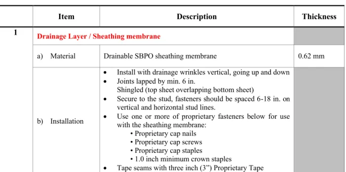
Table 4 – Client A Wall description of components differing from the Benchmark Wall assembly
Item Description Thickness
1 Drainage Layer / Sheathing membrane
a) Material Drainable SBPO sheathing membrane 0.62 mm
b) Installation
Install with drainage wrinkles vertical, going up and down Joints lapped by min. 6 in.
Shingled (top sheet overlapping bottom sheet)
Secure to the stud, fasteners should be spaced 6-18 in. on vertical and horizontal stud lines.
Use one or more of proprietary fasteners below for use with the sheathing membrane:
• Proprietary cap nails • Proprietary cap screws • Proprietary cap staples
• 1.0 inch minimum crown staples
Tape seams with three inch (3”) Proprietary Tape
GALVANIZED STAPLE
INTERIOR EXTERIOR
3 COAT STUCCO
EXPANDED DIAMOND-MESH METAL LATH BUILDING PAPER CAN-CGSB 51.32
DRAINABLE SBPO SHEATHING MEMBRANE OSB SHEATHING BOARD
38 x 140 MM (2 x 6) FRAMING / STUD CAVITY WITH RSI 3.5 (R20) GLASS FIBRE BATTS POLYETHYLENE AIR/VAPOUR BARRIER GYPSUM BOARD
Figure 5 – Client A Wall vertical cross section
3 COAT STUCCO
EXPANDED DIAMOND-MESH METAL LATH BUILDING PAPER CAN-CGSB 51.32
DRAINABLE SBPO SHEATHING MEMBRANE
OSB SHEATHING BOARD
38 x 140 MM (2 x 6) FRAMING / STUD CAVITY WITH RSI 3.5 (R20) GLASS FIBRE BATTS
POLYETHYLENE AIR/VAPOUR BARRIER GYPSUM BOARD INTERIOR EXTERIOR CASING BEAD RIGID FLASHING MIN. 10 MM MIN. UPWARD EXTENSION BEHIND WRB: 50 MM SHEATHING MEMBRANE SEALED TO DUCT SEALANT BETWEEN STUCCO AND DUCT
BUILDING PAPER LAPPED MIN. 100 MM SHEATHING MEMBRANE LAPPED MIN. 152 MM (6 IN.) SELF-ADHERED MEMBRANE 6% SEALED AT TOP OF WALL CONTINUOUS OPENING AT BASE OF WALL (MIN. 10 MM)
TASK 1 – WALL ASSEMBLY SPECIFICATIONS
REPORT A1-000030.01 12
Client B Wall Assembly Details
The Client B assembly is the only non-combustible wall assembly in the set of ten client walls. This wall features a number of elements that differentiate it from the benchmark wall, including two proprietary
elements: the water repellent insulation board and the liquid applied membrane7. Because of the exterior
gypsum board and the steel stud framing, the mode of failure for this wall will differ from the residential wood-frame walls. For wood-frame walls with OSB sheathing, the mode of failure is potential mold growth on wood components (due to high moisture content in the OSB and framing). For the commercial assembly, the mode of failure is the potential of corrosion of metal components. The Client B wall is vented and flashed at the bottom of the wall every 3.5 storeys.
In identical fashion to the benchmark wall, the Client B Wall features stucco applied to expanded metal lath (no paper backing) on 19 mm strapping.
Figure 6 – Client B Wall horizontal cross section
7 Note: if the water vapor permeance of the exterior sheathing with coating is below 60 ng, then the amount of
insulation must comply with NBC Table 9.25.5.2. for the respective heating degree days of building location. INTERIOR
EXTERIOR
3 COAT STUCCO
EXPANDED DIAMOND-MESH METAL LATH WITH NO PAPER BACKING
AIRSPACE with 19x64 mm (1x3) furring strips 400 mm (16 in.) o.c.
76 mm WATER REPELLENT INSULATION BOARD LIQUID APPLIED MEMBRANE
12.5 EXTERIOR GYPSUM BOARD
89 mm MINERAL FIBRE BATT with STEEL STUD FRAMING
POLYETHYLENE VAPOUR BARRIER INTERIOR GYPSUM BOARD
127 MM (5 IN.) SELF-TAPPING ROOFING SCREW
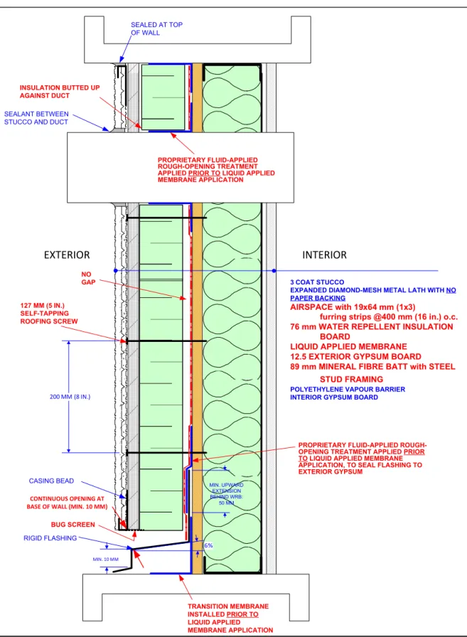
Figure 7 – Client B Wall vertical cross section 3 COAT STUCCO
EXPANDED DIAMOND-MESH METAL LATH WITH NO PAPER BACKING
AIRSPACE with 19x64 mm (1x3)
furring strips @400 mm (16 in.) o.c. 76 mm WATER REPELLENT INSULATION
BOARD
LIQUID APPLIED MEMBRANE 12.5 EXTERIOR GYPSUM BOARD 89 mm MINERAL FIBRE BATT with STEEL
STUD FRAMING POLYETHYLENE VAPOUR BARRIER INTERIOR GYPSUM BOARD
INTERIOR EXTERIOR CASING BEAD RIGID FLASHING 6% MIN. 10 MM MIN. UPWARD EXTENSION BEHIND WRB: 50 MM INSULATION BUTTED UP AGAINST DUCT SEALANT BETWEEN STUCCO AND DUCT
PROPRIETARY FLUID-APPLIED ROUGH-OPENING TREATMENT APPLIED PRIOR TO LIQUID APPLIED MEMBRANE APPLICATION
BUG SCREEN
PROPRIETARY FLUID-APPLIED ROUGH-OPENING TREATMENT APPLIED PRIOR TO LIQUID APPLIED MEMBRANE APPLICATION, TO SEAL FLASHING TO EXTERIOR GYPSUM 200 MM (8 IN.) 127 MM (5 IN.) SELF-TAPPING ROOFING SCREW NO GAP TRANSITION MEMBRANE INSTALLED PRIOR TO LIQUID APPLIED MEMBRANE APPLICATION SEALED AT TOP OF WALL CONTINUOUS OPENING AT BASE OF WALL (MIN. 10 MM)
TASK 1 – WALL ASSEMBLY SPECIFICATIONS
REPORT A1-000030.01 14
Table 5 – Client B Wall description of components differing from the Benchmark Wall assembly
Item Description Thickness
1 Framing
a) Material 30 x 91 (gauge 20) steel stud 91 mm
b) Spacing Studs @ 400 mm o.c. c) Runners Top and bottom 2 Insulation
a) Material Mineral wool batt insulation 89 mm
3 Sheathing
a) Material Exterior gypsum board 12.7 mm
b) Installation 2 mm gap between panels
c) Fastening
- Fastened with screws spaced 200 mm (8 in.) o.c. at perimeter and 200 mm (8 in.) o.c. along intermediate framing
- Fasteners drive to bear tight against and flush with the surface of the sheathing, not countersunk.
- Fasteners located a minimum of 3/8 in. from edges and ends of sheathing panels
4 Air/Vapour Retarder
a) Material Liquid applied membrane 0.152 mm
b) Installation As per manufacturer specifications 5 Rainscreen Insulation
a) Material Water Repellent Insulation Board 70 mm
b) Installation Installed with batts horizontal. Held in place by vertical 19 x 64 mm (1x3) wood furring strips c) Fastening 5 in. self-tapping roofing screws, fastened every 200 mm (8 in.) vertically 6 Vapour barrier
a) Material Polyethylene 0.15 mm
Client C Wall Assembly Details
The Client C assembly features 10 mm, open matrix nylon mesh bonded to a PP nonwoven sheathing membrane. The mesh is separated from the stucco cladding by a layer of building paper (meeting CAN-CGSB 51.32). All other elements of the assembly are identical to the benchmark wall. The Client C wall is vented and flashed at the bottom of the wall every 3.5 storeys.
Figure 8 – Client C Wall horizontal cross section
Table 6 – Client C Wall description of components differing from the Benchmark Wall assembly
Item Description Thickness
1 Drainage Layer / Sheathing membrane
a) Material Nylon mesh (nominal 10 mm, open matrix) bonded to PP nonwoven sheathing membrane 10.5 mm
b) Installation
Installed horizontally
Nailed or stapled (min. ½ in. staple) every 3 square feet Sheathing membrane at horizontal joints lapped by min. 100
mm, with matting butted
Shingled (top sheet overlapping bottom sheet)
Vertical joints flashed underneath (by a piece of 12 inch wider WRB or flashing tape)
GALVANIZED STAPLE
INTERIOR EXTERIOR
3 COAT STUCCO
EXPANDED DIAMOND-MESH METAL LATH BUILDING PAPER CAN-CGSB 51.32
NYLON MESH (10 mm, open matrix) BONDED TO PP NONWOVEN SHEATHING MEMBRANE OSB SHEATHING BOARD
38 x 140 MM (2 x 6) FRAMING / STUD CAVITY WITH RSI 3.5 (R20) GLASS FIBRE BATTS POLYETHYLENE AIR/VAPOUR BARRIER GYPSUM BOARD
TASK 1 – WALL ASSEMBLY SPECIFICATIONS
REPORT A1-000030.01 16
Figure 9 – Client C Wall vertical cross section
INTERIOR EXTERIOR CASING BEAD RIGID FLASHING MIN. 10 MM MIN. UPWARD EXTENSION BEHIND WRB: 50 MM SHEATHING MEMBRANE SEALED TO DUCT SEALANT BETWEEN STUCCO AND DUCT
BUILDING PAPER LAPPED
MIN. 100 mm
3 COAT STUCCO
EXPANDED DIAMOND-MESH METAL LATH BUILDING PAPER CAN-CGSB 51.32
NYLON MESH (10 mm, open matrix) BONDED TO PP NONWOVEN SHEATHING MEMBRANE
OSB SHEATHING BOARD
38 x 140 MM (2 x 6) FRAMING / STUD CAVITY WITH RSI 3.5 (R20) GLASS FIBRE BATTS POLYETHYLENE AIR/VAPOUR BARRIER GYPSUM BOARD ENDS OF MATTING BUTTED SHEATHING MEMBRANE LAPPED MIN. 100 MM BUG SCREEN (1/8 IN. MAX HOLE SIZE) EXTENDS 76 MM (3 IN.) ABOVE BOTTOM EDGE OF MATTING
SELF-ADHERED MEMBRANE 6%
SEALED AT TOP OF WALL
CONTINUOUS OPENING AT BASE OF WALL (MIN. 10 MM)
Client D Wall Assembly Details
The Client D assembly features a cross woven, micro-perforated polyolefin sheathing membrane with polyolefin coating, acting both as the drainage layer and as the sheathing membrane. The membrane is separated from the stucco cladding by a layer of building paper (meeting CAN-CGSB 51.32) (i.e. paper-backed lath). All other elements of the assembly are identical to the benchmark wall. The Client D wall is vented and flashed at the bottom of the wall every 3.5 storeys.
Figure 10 – Client D Wall horizontal cross section
Table 7 – Client D Wall description of components differing from the Benchmark Wall assembly
Item Description Thickness
1 Drainage Layer / Sheathing membrane
a) Material cross woven, micro-perforated polyolefin sheathing membrane with polyolefin coating 0.76 mm (0.03 in.)
b) Installation
Installed horizontally, printed side facing out
Fasteners penetrate studs a minimum of 13 mm (1/2 in.), spaced every 406 mm (16 in.) along every other stud location
Vertical and horizontal seams overlapped a minimum of 152 mm (6 in.) vertically, and 50 mm (2 in.) horizontally Singled (top sheet overlapping bottom sheet)
Seams sealed with proprietary contractor tape
INTERIOR EXTERIOR
3 COAT STUCCO
EXPANDED DIAMOND-MESH METAL LATH BUILDING PAPER CAN-CGSB 51.32
CROSS WOVEN, MICRO-PERFORATED POLYOLEFIN SHEATHING MEMBRANE WITH POLYOLEFIN COATING
11 mm (7/16 in.) OSB SHEATHING BOARD 38 x 140 MM (2 x 6) FRAMING @ 400 mm o.c.
WITH RSI 3.5 (R20) MINERAL FIBRE BATTS 6 mil POLYETHYLENE AIR/VAPOUR BARRIER 13 mm (½ in.) GYPSUM BOARD
TASK 1 – WALL ASSEMBLY SPECIFICATIONS
REPORT A1-000030.01 18
Figure 11 – Client D Wall vertical cross section
3 COAT STUCCO
EXPANDED DIAMOND-MESH METAL LATH BUILDING PAPER CAN-CGSB 51.32
CROSS WOVEN, MICRO-PERFORATED POLYOLEFIN SHEATHING MEMBRANE WITH POLYOLEFIN COATING
11 mm (7/16 in.) OSB SHEATHING BOARD 38 x 140 MM (2 x 6) FRAMING @ 400 mm o.c.
WITH RSI 3.5 (R20) MINERAL FIBRE BATTS
6 mil POLYETHYLENE AIR/VAPOUR BARRIER 13 mm (½ in.) GYPSUM BOARD
INTERIOR EXTERIOR CASING BEAD RIGID FLASHING MIN. 10 MM MIN. UPWARD EXTENSION BEHIND WRB: 50 MM SHEATHING MEMBRANE SEALED TO DUCT SEALANT BETWEEN STUCCO AND DUCT
BUILDING PAPER LAPPED
MIN. 100 MM SHEATHING MEMBRANE LAPPED MIN.
50 MM (2 IN.) LAP SEALED WITH CONTRACTOR TAPE SELF-ADHERED MEMBRANE 6% SEALED AT TOP OF WALL CONTINUOUS OPENING AT BASE OF WALL (MIN. 10 MM)
Client E Wall Assembly Details
The Client E assembly features a dimpled HDPE membrane that includes a stucco screen (a layer of PP fabric) to help keep stucco out of the drainage layer. This product acts as a drainage medium, and not as a sheathing membrane to protect the wood based sheathing. This dimpled membrane is a low-permeance material and the NBC requires that it be installed outboard of a 10-mm airspace from the exterior sheathing to meet condensation control requirements. The function of the sheathing membrane is performed by a layer of building paper (meeting CAN-CGSB 51.32) on the face of the OSB sheathing board. By using the code minimum required building paper, if adequate performance is demonstrated, the drainage product will be an acceptable solution for use with all code compliant sheathing membranes. All other elements of the assembly are identical to the benchmark wall. The Client E wall has two potential ventilation strategies: Option 1: vented and flashed at the bottom of the wall every 3.5 storeys (as per the benchmark specification), or Option 2: ventilated at the top and bottom of the wall every 2 storeys (as per the manufacturer’s installation recommendations).
Figure 12 – Client E Wall horizontal cross section
INTERIOR EXTERIOR
3 COAT STUCCO
EXPANDED DIAMOND-MESH METAL LATH
PP FABRIC BONDED TO DIMPLED HDPE MEMBRANE
BUILDING PAPER CAN-CGSB 51.32 OSB SHEATHING BOARD
38 x 140 MM (2 x 6) FRAMING / STUD CAVITY WITH RSI 3.5 (R20) GLASS FIBRE BATTS POLYETHYLENE AIR/VAPOUR BARRIER GYPSUM BOARD
TASK 1 – WALL ASSEMBLY SPECIFICATIONS
REPORT A1-000030.01 20
Figure 13 – Client E Wall vertical cross section Option 1 – Vented detail
INTERIOR EXTERIOR CASING BEAD RIGID FLASHING MIN. 10 MM MIN. UPWARD EXTENSION BEHIND WRB: 50 MM SHEATHING MEMBRANE SEALED TO DUCT SEALANT BETWEEN STUCCO AND DUCT
3 COAT STUCCO
EXPANDED DIAMOND-MESH METAL LATH
PP FABRIC BONDED TO DIMPLED HDPE MEMBRANE
BUILDING PAPER CAN-CGSB 51.32 OSB SHEATHING BOARD
38 x 140 MM (2 x 6) FRAMING / STUD CAVITY WITH RSI 3.5 (R20) GLASS FIBRE BATTS POLYETHYLENE AIR/VAPOUR BARRIER GYPSUM BOARD BUILDING PAPER LAPPED MIN. 100 MM BUG SCREEN ENDS OF DIMPLED MEMBRANE BUTTED DIMPLED MEMBRANE BUTTED AGAINST DUCT SELF-ADHERED MEMBRANE 6% SEALED AT TOP OF WALL CONTINUOUS OPENING AT BASE OF WALL (MIN. 10 MM)
Figure 14 – Client E Wall vertical cross section Option 2 – Ventilated detail INTERIOR EXTERIOR CASING BEAD RIGID FLASHING MIN. 10 MM MIN. UPWARD EXTENSION BEHIND WRB: 50 MM SHEATHING MEMBRANE SEALED TO DUCT SEALANT BETWEEN STUCCO AND DUCT
3 COAT STUCCO
EXPANDED DIAMOND-MESH METAL LATH
PP FABRIC BONDED TO DIMPLED HDPE MEMBRANE
BUILDING PAPER CAN-CGSB 51.32 OSB SHEATHING BOARD
38 x 140 MM (2 x 6) FRAMING / STUD CAVITY WITH RSI 3.5 (R20) GLASS FIBRE BATTS POLYETHYLENE AIR/VAPOUR BARRIER GYPSUM BOARD BUILDING PAPER LAPPED MIN. 100 MM BUG SCREEN ENDS OF DIMPLED MEMBRANE BUTTED DIMPLED MEMBRANE BUTTED AGAINST DUCT SELF-ADHERED MEMBRANE 6% BUG SCREEN WOOD BLOCKING CUT TO FIT MOLDING PIECE MIN. 50 MM LEG MIN. 10 MM GAP BETWEEN FLASHINGS CONTINUOUS OPENING AT BASE OF WALL (MIN. 10 MM)
TASK 1 – WALL ASSEMBLY SPECIFICATIONS
REPORT A1-000030.01 22
Table 8 – Client E Wall description of components differing from the Benchmark Wall assembly
Item Description Thickness
1 Drainage Layer
a) Material PP fabric bonded to dimpled HDPE membrane 10.6 mm
b) Installation
Detail at base of wall
Flashing with drip edge installed at bottom of wall, building paper shingle laps over flashing
Bug screen fastened to the flashing, aligned with planned bottom termination of bottom edge of cladding
Rainscreen installation
Installed horizontally with the mortar screen facing the exterior Begin fastening in the middle of the membrane, fasten a
maximum of every 600 mm (24 in.) horizontally, fasten to studs wherever possible
Butt ends together, do not overlap or interlock
Fasten end laps every 30 cm (12 in.) vertically, and side laps every 30 cm (12 in.) horizontally
Client F Wall Assembly Details
The Client F wall is already fully code compliant. The interest in evaluating this wall is to compare the performance of an airspace provided by 25 mm wood strapping to the benchmark stucco performance (with 18 mm strapping). The Client F wall is vented and flashed at the bottom of the wall every 3.5 storeys.
Figure 15 – Client F Wall horizontal cross section
Table 9 – Client F Wall description of components differing from the Benchmark Wall assembly
Item Description Thickness
1 Drainage Layer
a) Material Air space created by 25 x 38 mm wood strapping
Since lath not paper backed, stucco expected to protrude through lath and partially fill 25 mm airspace.
Nominal 25 mm b) Installation Fastened to framing @ 400 o.c.
c) Venting Vented at the bottom of the wall
INTERIOR EXTERIOR
3 COAT STUCCO
EXPANDED DIAMOND-MESH METAL LATH
AIRSPACE CREATED BY 25 mm STRAPPING
BUILDING PAPER CAN-CGSB 51.32 OSB SHEATHING BOARD
38 x 140 MM (2 x 6) FRAMING / STUD CAVITY WITH RSI 3.5 (R20) GLASS FIBRE BATTS POLYETHYLENE AIR/VAPOUR BARRIER GYPSUM BOARD
25 x 38 mm WOOD STRAPPING @ 400 mm o.c.
TASK 1 – WALL ASSEMBLY SPECIFICATIONS
REPORT A1-000030.01 24
Figure 16 – Client F Wall vertical cross section INTERIOR EXTERIOR CASING BEAD RIGID FLASHING MIN. 10 MM MIN. UPWARD EXTENSION BEHIND WRB: 50 MM BUILDING PAPER SEALED TO DUCT SEALANT BETWEEN STUCCO AND DUCT
BUILDING PAPER LAPPED
MIN. 100 mm
3 COAT STUCCO
EXPANDED DIAMOND-MESH METAL LATH AIRSPACE CREATED BY 25 mm WOOD
STRAPPING @ 400 mm o.c. BUILDING PAPER CAN-CGSB 51.32 OSB SHEATHING BOARD
38 x 140 MM (2 x 6) FRAMING / STUD CAVITY WITH RSI 3.5 (R20) GLASS FIBRE
BATTS
POLYETHYLENE AIR/VAPOUR BARRIER GYPSUM BOARD SELF-ADHERED MEMBRANE 6% SEALED AT TOP OF WALL CONTINUOUS OPENING AT BASE OF WALL (MIN. 10 MM)
Client G Wall Assembly Details
The Client G assembly features a PP mat (10 mm, 3-dimensional extruded PP mono-filament mesh) with a layer of Non-woven PP fabric to help keep stucco out of the rainscreen layer. This product acts as drainage medium, and not a sheathing membrane. The function of the sheathing membrane is performed by a layer of building paper (meeting CAN-CGSB 51.32) on the face of the OSB sheathing board. By using the code minimum required building paper, if adequate performance is demonstrated, the drainage product will be an acceptable solution for use with all code compliant sheathing membranes. All other elements of the assembly are identical to the benchmark wall. The Client G wall is vented and flashed at the bottom of the wall every 3.5 storeys
Figure 17 – Client G Wall horizontal cross section
Table 10 – Client G Wall description of components differing from the Benchmark Wall assembly
Item Description Thickness
1 Drainage Layer
d) Material Non-woven PP fabric (stucco screen) attached to PP mat (nominal 10 mm 3-dimensional extruded PP mono-filament mesh) 9.3 mm
e) Installation
Install horizontally, fabric side out with entangled core facing the building interior
Mechanically fasten with a cap nail, cap stable or cap screw, one fastener per square foot
Seam adjacent pieces with the selvage edge overlapping the top of the lower piece
Trim around all penetrations, windows and doors
GALVANIZED STAPLE
INTERIOR EXTERIOR
3 COAT STUCCO
NON-WOVEN PP FABRIC (STUCCO SCREEN) ATTACHED TO PP MAT (10 MM, 3-DIMENSIONAL EXTRUDED PP MONO-FILAMENT MESH)
BUILDING PAPER CAN-CGSB 51.32 OSB SHEATHING BOARD
38 x 140 MM (2 x 6) FRAMING / STUD CAVITY WITH RSI 3.5 (R20) GLASS FIBRE BATTS POLYETHYLENE AIR/VAPOUR BARRIER GYPSUM BOARD
TASK 1 – WALL ASSEMBLY SPECIFICATIONS
REPORT A1-000030.01 26
Figure 18 – Client G Wall vertical cross section INTERIOR EXTERIOR CASING BEAD RIGID FLASHING MIN. 10 MM MIN. UPWARD EXTENSION BEHIND WRB: 50 MM CONTINUOUS OPENING AT BASE OF WALL (MIN. 10 MM)
BUILDING PAPER SEALED TO DUCT SEALANT BETWEEN STUCCO AND DUCT
SELVAGE EDGE OF PP FABRIC OVERLAPPING
3 COAT STUCCO
NON-WOVEN PP FABRIC (STUCCO SCREEN) ATTACHED TO PP MAT (10 MM, 3-DIMENSIONAL EXTRUDED PP MONO-FILAMENT MESH)
BUILDING PAPER CAN-CGSB 51.32 OSB SHEATHING BOARD
38 x 140 MM (2 x 6) FRAMING / STUD CAVITY WITH RSI 3.5 (R20) GLASS FIBRE BATTS POLYETHYLENE AIR/VAPOUR BARRIER GYPSUM BOARD ENDS OF MESH BUTTED BUILDING PAPER LAPPED MIN. 100 MM SELF-ADHERED MEMBRANE 6% SEALED AT TOP OF WALL
Client H Wall Assembly Details
The Client H assembly features a drainable insulation layer adhered to a fluid applied air barrier8. These
products will be considered a system, linked together. Thus, if adequate performance is demonstrated, the drainable insulation will only be approved for installation in conjunction with the fluid applied air barrier. All other elements of the assembly are identical to the benchmark wall. The Client H wall is vented and flashed at the bottom of the wall every 3.5 storeys.
Figure 19 – Client H Wall horizontal cross section
Table 11 – Client H Wall description of components differing from the Benchmark Wall assembly
Item Description Thickness
1 Air/Vapour Retarder
a) Material Liquid applied membrane 0.305 mm
b) Installation As per manufacturer’s instructions 2 Drainable Insulation
a) Material Porous PS insulation board 51 mm
b) Installation Adhered to surface of liquid applied membrane using a uniform layer of proprietary liquid adhesive. 3 a) Stucco lath
-fastening Cap nails, penetrating a minimum of 19 mm into the framing. Fastened 100 mm o.c. vertically, and 600 o.c. horizontally 6 Vapour barrier
a) Material Polyethylene 0.15 mm
b) Installation Not continuous or sealed
8 Note: If the water vapor permeance of the exterior sheathing with the liquid applied membrane is < 60ng, the
required insulation must comply with NBC table 9.25.5.2. for the heating degree days of the building location. INTERIOR
EXTERIOR
3 COAT STUCCO
POROUS PS INSULATION BOARD LIQUID ADHESIVE
LIQUID APPLIED MEMBRANE OSB SHEATHING BOARD
38 x 140 MM (2 x 6) FRAMING / STUD CAVITY WITH RSI 3.5 (R20) GLASS FIBRE BATTS POLYETHYLENE VAPOUR BARRIER GYPSUM BOARD
CAP SCREW TO FASTEN LATH THROUGH INSULATION TO STUDS
TASK 1 – WALL ASSEMBLY SPECIFICATIONS
REPORT A1-000030.01 28
Figure 20 – Client H Wall vertical cross section
INTERIOR CASING BEAD RIGID FLASHING MIN. 10 MM MIN. UPWARD EXTENSION BEHIND WRB: 50 MM SEALANT BETWEEN
STUCCO AND DUCT
3 COAT STUCCO
POROUS PS INSULATION BOARD LIQUID ADHESIVE
LIQUID APPLIED MEMBRANE
OSB SHEATHING BOARD
38 x 140 MM (2 x 6) FRAMING / STUD CAVITY WITH RSI 3.5 (R20) GLASS FIBRE BATTS
POLYETHYLENE VAPOUR BARRIER GYPSUM BOARD
INSULATION BOARD BUTTED UP AGAINST DUCT
CAP SCREW TO FASTEN LATH TO STUDS THROUGH INSULATION
PROPRIETARY LIQUID-APPLIED ROUGH-OPENING TREATMENT APPLIED PRIOR TO LIQUID APPLIED MEMBRANE
PROPRIETARY FLUID-APPLIED ROUGH-OPENING TREATMENT APPLIED PRIOR TO FLUID AIR BARRIER APPLICATION, TO SEAL FLASHING TO OSB
6%
TRANSITION MEMBRANE INSTALLED PRIOR TO FLUID AIR BARRIER APPLICATION INSULATION BOARD ADHERED TO AIR BARRIER EXTERIOR ENDS OF INSULATION BOARDS BUTTED (NO ADHESIVE)
SEALED AT TOP OF WALL
CONTINUOUS OPENING AT BASE OF WALL (MIN. 10 MM)
Client I Wall Assembly Details
The Client I assembly features a layer of 2-ply corrugated asphalt impregnated paper. This product is intended to act as a drainage medium, and is not intended to perform as the sheathing membrane. A layer of building paper (conforming to CAN-CGSB 51.32) installed on the face of the OSB sheathing board will perform the function of the sheathing membrane. By using the code minimum required building paper, if adequate performance is demonstrated, the drainage product will be an acceptable solution for use with all code compliant sheathing membranes. The drainage layer has a ventilated detail, open at the top and bottom of the wall section. All other elements of the assembly are identical to the benchmark wall. The Client I wall is ventilated at the top and bottom of the wall every storey.
Figure 21 – Client I Wall horizontal cross section
Table 12 – Client I Wall description of components differing from the Benchmark Wall assembly
Item Description Thickness
1 Drainage layer
a) Material 2-ply corrugated asphalt impregnated paper, Grade D 3.8 mm
b) Installation
Install with corrugations facing inwards
Bottom flap protrudes past the lowest point of the cladding, trimmed off
Flap from upper layer should overlap the lower sheet by 100 mm (4 in.), leaving a 12 mm (1/2 in.) gap between corrugations Vertical joints taped with construction tape, or covered with a
300 mm (12 in) wide strip of building paper
Horizontal mid wall flashing installed at each floor level c) Fastening Fastened with 3/8” or ½” galvanized staples to the wall with a hand stapler d) Venting Ventilated – open at both the top and bottom of the wall section
INTERIOR EXTERIOR
3 COAT STUCCO
EXPANDED DIAMOND-MESH METAL LATH
2 PLY CORRUGATED ASPHALT IMPREGNANTED PAPER
BUILDING PAPER CAN-CGSB 51.32 OSB SHEATHING BOARD
38 x 140 MM (2 x 6) FRAMING / STUD CAVITY WITH RSI 3.5 (R20) GLASS FIBRE BATTS POLYETHYLENE AIR/VAPOUR BARRIER GYPSUM BOARD
TASK 1 – WALL ASSEMBLY SPECIFICATIONS
REPORT A1-000030.01 30
Figure 22 – Client I Wall vertical cross section
INTERIOR EXTERIOR CASING BEAD RIGID FLASHING MIN. 10 MM MIN. UPWARD EXTENSION BEHIND WRB: 50 MM SHEATHING MEMBRANE SEALED TO DUCT USING CAULKING 3 COAT STUCCO
EXPANDED DIAMOND-MESH METAL LATH 2 PLY CORRUGATED ASPHALT
IMPREGNANTED PAPER BUILDING PAPER CAN-CGSB 51.32 OSB SHEATHING BOARD
38 x 140 MM (2 x 6) FRAMING / STUD CAVITY WITH RSI 3.5 (R20) GLASS FIBRE BATTS POLYETHYLENE AIR/VAPOUR BARRIER GYPSUM BOARD
BUILDING PAPER LAPPED MIN. 100 MM CORRUGATED PAPER
SEALED TO DUCT USING SILICON OR ASPHALT BASED CAULKING 12 MM GAP BETWEEN CORRUGATIONS RIGID FLASHING CASING BEAD MIN. 6 MM 3.5 MM 6% CORRUGATED PAPER BOTTOM FLAP LAPPED 100 MM SEALANT BETWEEN STUCCO AND DUCT
Min. 50 MM SELF-ADHERED MEMBRANE 6% SEALANT CONTINUOUS OPENING AT BASE OF WALL (3.5 MM)
Client J Wall Assembly Details
The Client J wall was designed to represent west-coast residential construction. The primary difference between this wall and the benchmark wall is the type of lath – a paper backed welded wire mesh. Unlike the benchmark wall, this configuration is less likely to allow stucco to protrude into the airspace behind the cladding. The Client J wall uses 9.5 mm (3/8 in.) treated plywood strapping. The 9.5 mm gap is specified by BCBC 2012, 9.27.2.2(1)(a), and is less than the 10 mm specified by the National Building Code. The benchmark employed a slightly larger strapping (19 mm [3/4 in.]) to ensure a clear 10 mm airspace, and to accommodate the stucco entering the drainage cavity through the diamond mesh lath. Additionally, the Client J wall has 2 layers of code compliant building paper as a second line of defense. The Client J wall is vented and flashed at the bottom of the wall every 3.5 storeys.
Figure 23 – Client J Wall horizontal cross section
Table 13 – Client J Wall description of components differing from the Benchmark Wall assembly
Item Description Thickness
1 Drainage Layer
a) Material Air space created by 9.5 mm (3/8 in.) plywood strapping 9.5 mm b) Installation Strapping fastened to framing @ 400 mm o.c.
2 Cladding
a) Lath Paper backed welded-wire mesh lath (1.5 or 2 in.) b) Lath
Fastening
Fastened to framing through strapping with corrosion-resistant staples, 1.98 mm thick, 50 mm long (to penetrate min. 25 mm into framing)
100 mm o.c. vertically 400 mm o.c. horizontally 3 Sheathing Membrane
c) Material 2 x asphalt-impregnated building paper complying with CAN/CGSB-51.32-M 0.2 mm d) Installation Installed (nailed or stapled) horizontallyJoints lapped by min. 100mm
Shingled (top sheet overlapping bottom sheet)
GALVANIZED STAPLE
INTERIOR EXTERIOR
3 COAT STUCCO
PAPER BACKED WELDED-WIRE MESH LATH (1.5 or 2 in.)
9.5 mm (3/8 in) x 38 mm TREATED PLYWOOD STRAPPING @ 400 mm o.c. WITH AIR SPACE
2 LAYERS of BUILDING PAPER CAN-CGSB 51.32
11 mm (7/16 in.) OSB SHEATHING BOARD 38 x 140 MM (2 x 6) FRAMING @ 400 mm o.c.
WITH RSI 3.5 (R20) MINERAL FIBRE BATTS 6 mil POLYETHYLENE AIR/VAPOUR BARRIER 13 mm (½ in.) GYPSUM BOARD
TASK 1 – WALL ASSEMBLY SPECIFICATIONS
REPORT A1-000030.01 32
Figure 24 – Client J Wall vertical cross section INTERIOR EXTERIOR CASING BEAD RIGID FLASHING MIN. 10 MM MIN. UPWARD EXTENSION BEHIND WRB: 50 MM BUG SCREEN BUILDING PAPER SEALED TO DUCT SEALANT BETWEEN STUCCO AND DUCT
BUILDING PAPER LAPPED
MIN. 100 mm
3 COAT STUCCO
PAPER BACKED WELDED-WIRE MESH LATH (1.5 or 2 in.)
9.5 mm (3/8 in) x 38 mm TREATED PLYWOOD STRAPPING @ 400 mm o.c. WITH AIR SPACE
2 LAYERS of BUILDING PAPER CAN-CGSB 51.32
11 mm (7/16 in.) OSB SHEATHING BOARD 38 x 140 MM (2 x 6) FRAMING @ 400 mm o.c.
WITH RSI 3.5 (R20) MINERAL FIBRE BATTS 6 mil POLYETHYLENE AIR/VAPOUR BARRIER 13 mm (½ in.) GYPSUM BOARD
SELF-ADHERED MEMBRANE 6%
CONTINUOUS OPENING AT BASE OF WALL (MIN. 10 MM)
SEALED AT TOP OF WALL
Client K Wall Assembly Details
The Client K wall is identical to the Client J wall with the exception of using 19 mm (3/4 in.) strapping in place of 9.5 (3/8 in.) strapping. The Client K wall is vented and flashed at the bottom of the wall every 3.5 storeys.
Figure 25 – Client K Wall horizontal cross section
Table 14 – Client K Wall description of components differing from the Benchmark Wall assembly
Item Description Thickness
1 Drainage Layer
c) Material Air space created by 19 mm (3/4 in.) plywood strapping 19 mm d) Installation Strapping fastened to framing @ 400 mm o.c.
2 Cladding
c) Lath Paper backed welded-wire mesh lath (1.5 or 2 in.) d) Lath
Fastening
Fastened to framing through strapping with corrosion-resistant staples, 1.98 mm thick, 50 mm long (to penetrate min. 25 mm into framing members)
100 mm o.c. vertically 400 mm o.c. horizontally 3 Sheathing Membrane
e) Material 2 x asphalt-impregnated building paper complying with CAN/CGSB-51.32-M77 0.2 mm f) Installation Installed (nailed or stapled) horizontallyJoints lapped by min. 100mm
Shingled (top sheet overlapping bottom sheet)
GALVANIZED STAPLE
INTERIOR EXTERIOR
3 COAT STUCCO
PAPER BACKED WELDED-WIRE MESH LATH (1.5 or 2 in.)
19 mm (3/4 in) x 38 mm TREATED PLYWOOD STRAPPING @ 400 mm o.c. WITH AIR SPACE
2 LAYERS of BUILDING PAPER CAN-CGSB 51.32
11 mm (7/16 in.) OSB SHEATHING BOARD 38 x 140 MM (2 x 6) FRAMING @ 400 mm o.c.
WITH RSI 3.5 (R20) MINERAL FIBRE BATTS 6 mil POLYETHYLENE AIR/VAPOUR BARRIER 13 mm (½ in.) GYPSUM BOARD
TASK 1 – WALL ASSEMBLY SPECIFICATIONS
REPORT A1-000030.01 34
Figure 26 – Client K Wall vertical cross section
INTERIOR EXTERIOR CASING BEAD RIGID FLASHING MIN. 10 MM MIN. UPWARD EXTENSION BEHIND WRB: 50 MM BUG SCREEN BUILDING PAPER SEALED TO DUCT SEALANT BETWEEN STUCCO AND DUCT
BUILDING PAPER LAPPED
MIN. 100 mm
3 COAT STUCCO
PAPER BACKED WELDED-WIRE MESH LATH (1.5 or 2 in.)
19 mm (3/4 in) x 38 mm TREATED PLYWOOD STRAPPING @ 400 mm o.c. WITH AIR SPACE 2 LAYERS of BUILDING PAPER CAN-CGSB 51.32
11 mm (7/16 in.) OSB SHEATHING BOARD 38 x 140 MM (2 x 6) FRAMING @ 400 mm o.c.
WITH RSI 3.5 (R20) MINERAL FIBRE BATTS 6 mil POLYETHYLENE AIR/VAPOUR BARRIER 13 mm (½ in.) GYPSUM BOARD
SELF-ADHERED MEMBRANE 6%
CONTINUOUS OPENING AT BASE OF WALL (MIN. 10 MM)
SEALED AT TOP OF WALL
5. Summary of Wall Assemblies
A summary of specifications given for each of the proponent’s wall assemblies is given in Table 15. The acronym designated “BM” indicates that the component is the same as the benchmark wall assembly. Note that an evaluation of hygrothermal properties was performed for the component highlighted in yellow.
Table 15 – Summary of Benchmark and Client Wall Assembly Elements Assembly Cladding Layer separating cladding from drainage layer
Drainage layer membraneSheathing Sheathing board Framing
Stud cavity insulatn
Air/Vapour
Barrier Interior finish Ventilatn Strategy Notes
Benchmark
3 coat Stucco with expanded diamond-mesh metal lath (no paper backing)
None
Air space created by 19x38 mm wood strapping @ 400 mm o.c. 1 layer of building paper CAN-CGSB 51.32 OSB 28 x 140 mm (2x6) wood stud framing @ 600 mm o.c. RSI 3.5 (R20) mineral fibre batts 6 mil polyethylene 13 mm (1/2 in.) gypsum board Vented at the base of the wall every 3.5 storeys Bug screen at base of wall
Client A BM paper CAN-Building CGSB 51.32
Drainable SBPO sheathing
membrane BM BM BM BM BM BM Client B BM BM (none) 10mm air space created by 19x64 mm wood strapping @ 400 mm o.c., with 76 mm water repellent insulationboard Fluid applied air barrier 12.5 mm Exterior gypsum board Steel stud framing 89 mm Mineral fibre batt 6 mil polyethylene vapour barrier, not continuous or sealed BM BM Client C BM Building paper CAN-CGSB 51.32
Nylon mesh (10 mm; open matrix) bonded to PP nonwoven
sheathing membrane BM BM BM BM BM BM
Client D BM paper CAN-Building CGSB 51.32
Cross woven, micro-perforated polyolefin sheathing membrane
with polyolefin coating BM BM BM BM BM BM
Client E BM PP fabric bonded to dimpled HDPE membrane BM BM BM BM BM BM
Option 1: BM Option 2: Ventilated top & bottom every 2 storeys Bug screen at base of wall
Assembly Cladding cladding from drainage
layer
Drainage layer membraneSheathing Sheathing board Framing cavity insulatn
Air/Vapour
Barrier Interior finish Ventilatn Strategy Notes
Client F BM BM (none) Nominal 25 mm Air space created by 25 x 38 mm wood strapping @ 400 mm o.c. BM BM BM BM BM BM BM Client G BM
Non-woven PP fabric (stucco screen) / PP mat (10 mm; 3-dimensional extruded PP
mono-filament mesh)
BM BM BM BM BM BM BM
Client H BM BM (none) insulation board Porous PS (52 mm) Fluid applied air barrier BM BM BM 6 mil polyethylene vapour barrier, not continuous or sealed BM BM Client I BM BM (none) 2-ply corrugated asphalt impregnanted paper – Grade D BM BM BM BM BM BM Ventilated top and bottom every storey Client J BM Building paper CAN-CGSB 51.32
Air space created by 9.5x38 mm plywood strapping @ 400 mm o.c. 2 layers of building paper CAN-CGSB 51.32
BM BM BM BM BM BM Bug screen at base of wall
Client K BM paper CAN-Building CGSB 51.32
Air space created by 19 mm (3/4 in.) plywood strapping @ 400 mm o.c. 2 layers of building paper CAN-CGSB 51.32
![Figure 2 – Code-Compliant Reference wall horizontal cross section Specifications for West Coast wall assemblies under the jurisdiction of the HPO [5, 6]](https://thumb-eu.123doks.com/thumbv2/123doknet/14087394.464268/19.918.148.770.231.621/figure-compliant-reference-horizontal-section-specifications-assemblies-jurisdiction.webp)