HAL Id: hal-02360079
https://hal.archives-ouvertes.fr/hal-02360079
Submitted on 12 Nov 2019
HAL is a multi-disciplinary open access
archive for the deposit and dissemination of
sci-entific research documents, whether they are
pub-lished or not. The documents may come from
teaching and research institutions in France or
abroad, or from public or private research centers.
L’archive ouverte pluridisciplinaire HAL, est
destinée au dépôt et à la diffusion de documents
scientifiques de niveau recherche, publiés ou non,
émanant des établissements d’enseignement et de
recherche français ou étrangers, des laboratoires
publics ou privés.
One-shot measurement of the three-dimensional
electromagnetic field scattered by a subwavelength
aperture tip coupled to the environment
Nancy Rahbany, Ignacio Izeddin, Valentina Krachmalnicoff, Rémi Carminati,
Gilles Tessier, Yannick de Wilde
To cite this version:
Nancy Rahbany, Ignacio Izeddin, Valentina Krachmalnicoff, Rémi Carminati, Gilles Tessier, et al..
One-shot measurement of the three-dimensional electromagnetic field scattered by a subwavelength
aperture tip coupled to the environment. ACS photonics, American Chemical Society„ 2018.
�hal-02360079�
Nancy Rahbany
†, Ignacio Izeddin
†, Valentina Krachmalnicoff
†, Rémi Carminati
†, Gilles Tessier*
‡,
Yannick De Wilde*
††ESPCI Paris, PSL Research University, CNRS, Institut Langevin, 1 rue Jussieu, F-7500, Paris, France
‡Sorbonne Université UPMC Univ. Paris 06, Institut de la Vision, INSERM UMR_S968 CNRS UMR 7210, and CNRS
UMR 8250 Neurophotonics laboratory, 45 Rue des Saints Pères, 75006 Paris, France
KEYWORDS. Near-field scanning optical microscopy, digital holography, complex electromagnetic field reconstruc-tion, angular radiation pattern, leaky surface plasmons
ABSTRACT: Near-field scanning optical microscopy (NSOM) achieves subwavelength resolution by bringing a nanosized
probe close to the surface of the sample. This extends the spectrum of spatial frequencies that can be detected with re-spect to a diffraction limited microscope. The interaction of the probe with the sample is expected to affect its radiation to the far field in a way that is often hard to predict. Here we address this question by proposing a general method based on full-field off-axis digital holography microscopy which enables to study in detail the far-field radiation from a NSOM probe as a function of its environment. A first application is demonstrated by performing a three-dimensional (3D) tomo-graphic reconstruction of light scattered from the sub-wavelength aperture tip of a NSOM, in free space or coupled to transparent and plasmonic media. A single holographic image recorded in one shot in the far field contains information on both the amplitude and phase of the scattered light. This is sufficient to reverse numerically the propagation of the electromagnetic field all the way to the aperture tip. Finite Difference Time Domain (FDTD) simulations are performed to compare the experimental results with a superposition of magnetic and electric dipole radiation.
Near-field Scanning Optical Microscopy (NSOM) has prov-en to be a powerful tool for investigating the behavior of light at distances from the sample much smaller than its wavelength λ1. NSOM uses a scanning probe with a sub-λ
sized scatterer to measure the high frequency spatial compo-nents of the electromagnetic (EM) field, contained in the evanescent waves which are confined in the near field. This allows one to perform sub-λ imaging or to detect purely eva-nescent plasmonic fields. Conversely, the probe of a NSOM can be used to locally excite surface plasmon polaritons2.
However, a limitation of this method generally arises from the scarce information on the way the sub-λ probe of a NSOM scatters light to the far field, and how it reacts with the environment. Whereas it is worth noticing that surface plasmons excitation can also be achieved by alternative methods such as the use of tunneling electrons3,4, pointlike
dipoles5, or surface defects2,6, it is of great importance to
de-velop experimental approaches to characterize the scattering properties of NSOM tips and its coupling with the local envi-ronment.
Apertureless metallic NSOM tips in free space are usually modeled as effective electric dipoles producing a field en-hancement for the electric field component parallel to the tip axis7,6,8, but the coupling of such scattering tips to the
envi-ronment is a complex problem that needs to be taken into account. A metal coated sub-λ aperture at the extremity of a tapered fiber is a practical realization of a sub- hole in a
perfectly conducting plane screen initially studied theoreti-cally by Bethe9, which radiates in free space as a coherent
superposition of a magnetic and an electric dipole6,10–12. A
generalization of the two-dipole model has also been pro-posed based on multipole expansion to describe the far-field transmission pattern in free space13, while their resolving
power as near-field probe was addressed with a model using a ring-like current14 . Nevertheless, recent near-field optical
images of intensity measured on nanoantennas with a metal-coated aperture at the end of a hollow pyramidal probe sug-gest that the probe essentially behaves as a tangential mag-netic dipole when it is coupled to a metallic nanoantenna15.
Advanced fabrication techniques aim at achieving high con-trol of the optical response of optical nanoantennas as they can be directly installed at the extremity of NSOM probes16,17.
However, defects play an important role at the nanoscale18.
Each probe is therefore unique, and its radiation pattern may dramatically differ from expectations. Individual NSOM probe characterization is absolutely necessary to achieve quantitative measurements. Regardless of the type of probe used, placing it on the surface of a sample induces complex reflections and interferences in the EM field between the scattering probe and the surface. This results in a dressed polarizability of the coupled system and a radiation pattern which is difficult to predict, especially if the size of the scat-terer is not negligible with respect to λ or if the coupling is strong between the scatterer and the sample surface19,20.
There is thus an obvious need to characterize how the EM field is scattered by a nanostructure in a given environment. NSOM is the ideal playground for such a study as it allows to precisely control the coupling between a nanostructured probe and the local environment.
In the past, back focal plane imaging was successfully ap-plied to measure the far-field angular radiation pattern of leaky surface plasmons excited by a NSOM probe on a metal-lic thin film2,21,22. The information regarding the phase of the
EM field is inherently lost because the measurement is only based on the mapping of the intensity in the Fourier plane of an optical system16,23. In order to infer the EM field in any
plane, i.e. in three dimensions, a precise knowledge of both the amplitude and phase of the EM field is absolutely essen-tial.
In this paper, we demonstrate full three-dimensional (3D) far-field tomographic reconstruction in real space of the light scattered through a metal coated aperture pyramidal NSOM tip using Digital Holographic Microscopy (DHM)24. From a
single hologram recorded in the far field, both the amplitude and phase of the EM field can be calculated in the measure-ment plane and then back-propagated numerically towards the source, allowing a complete 3D representation of the EM field25. DHM was previously combined with NSOM for the
investigation of the super-resolving capabilities of disordered scattering media assuming that the aperture tip produces point-like illuminating fields26. Here, DHM is combined with
a NSOM to investigate in details how the light is scattered from its aperture tip when it is either in free space, above a glass surface, or above the surface of a metallic thin film on glass. The 3D reconstruction of the EM field scattered by the aperture tip in free space shows a broad angular distribution of intensity with a maximum in the forward direction. When the aperture tip is brought in contact with a glass surface, directional lobes at the critical angle of the glass/air interface are superimposed on the broad distribution, while a highly directional supercritical emission is measured when the ap-erture tip is at the surface of the metallic film on glass due to the excitation of leaky surface plasmons. Finite Difference Time Domain (FDTD) simulations support the approxima-tion of the aperture tip of the NSOM as a superposiapproxima-tion of electric and magnetic dipoles.
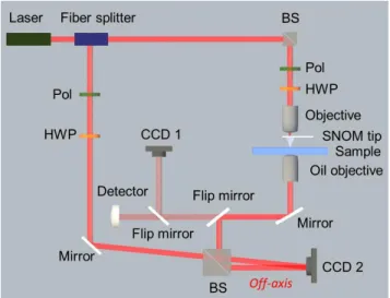
. Our optical setup is schematically depicted in Figure 1. It is composed of an off-axis DHM combined with a commercial NSOM27 modified to
allow interferometric measurements (see Measurement sec-tion). Light from a single mode 633 nm He-Ne laser is split into sample and reference beams. The sample beam is fo-cused on the apex of a metal coated aperture probe, which is either in free space or placed above a sample. SEM images of the probe provided by the manufacturer28 are shown in
Fig-ure 2.d. The sample is mounted on a piezoelectric three-axis translation stage, which allows one to bring its surface in contact with the aperture tip, or to finely adjust the tip height above the sample. The set-up operates in transmission mode with a high numerical aperture microscope objective used to collect the light emerging from the aperture tip. The collected light (through the substrate if any) is directed to a CCD camera where it interferes with the reference beam in an off-axis manner, creating a hologram. The hologram
pro-vides a one-shot measurement of the spatial variations of the amplitude and phase, which fully characterizes the wave front in the plane of the CCD camera. The propagation of EM fields is accurately described by diffraction theory by means of the angular spectrum representation6. Using
back-propagation, the amplitude and phase of the complex EM field at any point in space can thus be reconstructed by com-puting the scattered field in Fourier space (k-space), provid-ed that the propagation mprovid-edium is homogeneous.
Figure 1. Schematic of the optical setup: an off-axis digital holographic microscope (DHM) is combined with a near-field scanning optical microscope (NSOM) with aperture metal-coated hollow pyramidal tip. BS: beam splitter, Pol: polarizer, HWP: half-wave plate, CCD: charge coupled device camera.
With this approach, after investigating the radiation by the aperture tip in free space, we investigate the coupling of the tip with two types of samples: a transparent glass sample, and a plasmonic sample made of a 40 nm gold film deposited on a glass substrate (see Fabrication section). The recon-struction of the EM field scattered by the tip in various envi-ronments is achieved numerically after k-space filtering us-ing a method inspired by Cuche et al.24,25, as illustrated in
Figure 2.
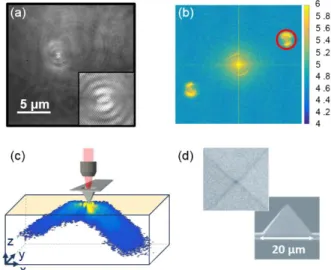
In Figure 2.a., we show a typical hologram, captured at the CCD plane, resulting from the interference between the ref-erence beam and the light scattered through the nanosized aperture of the NSOM tip when it is placed in contact with the plasmonic sample. Interference fringes typical of off-axis holography can be seen in the magnified image in the inset. The reconstruction is performed by first calculating the Fou-rier transform of the recorded real space hologram. In the k-space representation shown in Figure 2.b., the contributions of the zeroth order of diffraction appear near the center. Two interference terms, which are of interest to reconstruct a real (order +1) or a virtual (order -1) image of the EM field as they contain the amplitude and phase information, appear as sat-ellites symmetrically displayed along a diagonal on both sides of the zeroth order term. The separation in k-space results from the off-axis configuration where the sample beam is tilted by a few degrees with respect to the reference beam24. Only one interference term is kept after filtering in
k-space the Fourier transform of the hologram: the one re-quired to construct the real image, highlighted by a red circle
in Figure 2.b. If z corresponds to the propagation direction, the spatial Fourier transforms of the EM field in planes with different z values are linked by a simple propagator6.
Multi-plying the filtered Fourier transform of the hologram by the propagator allows one then to calculate the complex EM field in any z-plane after the NSOM tip by a simple inverse Fourier transform. In this way, a 3D stack of images giving a tomo-graphic reconstruction of the amplitude and phase of the EM field in the vicinity of the NSOM tip can be calculated from the measurement of a single hologram, as depicted in Figure 2.c. In a first approximation, the light source corresponding to this nano-aperture is point-like. The optical intensity therefore decreases very fast, as ρ-2, where ρ is the distance to
the tip in spherical coordinates. This sharp decrease is diffi-cult to represent, and we have therefore chosen, for clarity, to multiply the intensity maps by ρ2. Note that a similar
re-construction can be performed to map the phase of the EM field24.
Figure 2. Field reconstruction procedure. (a) Raw hologram of the scattered light from the nanosized aperture of a NSOM tip through a plasmonic sample made of a 40 nm gold film on a glass substrate. Inset: magnified image showing the in-terference fringes. (b) Fourier transform of the hologram (a) showing the 0th order of diffraction (around the image cen-ter) and the two interference terms (corresponding to the real and virtual images) in k-space. The real image term (in-side the red circle) is selected by spatial filtering. (c) 3D tomographic reconstruction of the scattered field intensity through the substrate up to a distance of 10 µm under the tip. (d) SEM images of the NSOM probe of aperture size ~150 nm28.
Applying this method, we compare the 3D radiation
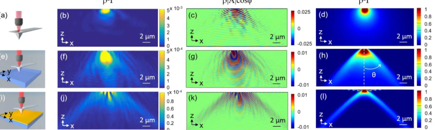
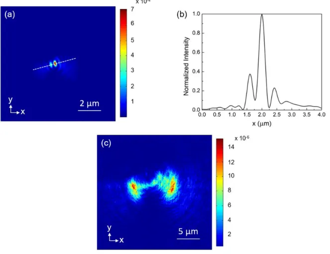
patterns of the light scattered by a NSOM tip placed either in free space, in contact with a glass coverslip– a dielectric sam-ple-, or on a metallic thin film on glass. 2D cross sections of the reconstructed EM field intensities are shown in Figure 3, in the x-z plane. This plane is perpendicular to the sample surface (x-y), contains the axis of the linearly-polarized illu-mination (x), and is perpendicular to the axis of the cantile-ver (y). As our method captures the complex EM field, we can also represent the wavefront reconstructions (Figures 3.c., 3.g., and 3.k.) obtained by multiplying the amplitude at each point in space |A(x,y,z)| by the cosine of the corre-sponding phase cos (x,y,z). We observe that in the free-space case (Figures 3.b. and 3.c.), which gives access to the intrinsic radiation pattern of the aperture tip without any coupling to the environment, light is only scattered forward beneath the tip with a broad angular distribution centered around θ = 0°. When the tip is in contact with the glass sam-ple (Figures 3.f. and 3.g.), light is still scattered in the forward direction (defined as θ = 0°) but two preferred radiation di-rections at the critical angle also appear as a result of the interaction with the air-glass interface. According to Snell’s law, = 41.8°. Interestingly, in Figures 3.j. and 3.k., we can clearly see that due to the presence of the gold film, leaky surface plasmons are generated that propagate along the metal surface and radiate into the glass substrate at specific angles, i.e. resonance angles, that satisfy the phase matching condition between surface plasmons at the air-metal interface and photons in glass. This explains the pres-ence of two narrow lobes in each term of the k-space repre-sentation of the hologram in Figure 2.b. Since the NSOM tip is illuminated by linearly polarized light, a direction of exci-tation of the surface plasmons is favored and their wavevec-tor must satisfy the phase matching condition, which results in the two lobes2. These lobes correspond to the directional
radiation that is clearly observed in the k-space in Figure 2.b., and in the object space in Figures 2.c. and 3.j. and 3.k. In addition, the x-y intensity images presented in Figure S1 (Supporting Information) show that the excited surface plasmons exhibit a double-lobed pattern due to the fact that they can only be excited by p-polarized field components2,6.
The resonance angle , which is the angle between the transmitted rays and the surface normal, can be calculated according to the conservation of parallel momentum equa-tion and the surface plasmon dispersion relaequa-tion, as follows:
Figure 3. Configuration with the nanosized aperture of a NSOM tip (a) in free space, and in contact with (e) a transparent glass substrate, and (i) a 40 nm gold film on a glass substrate. (b),(f),(j) are the corresponding 2D cross sections in the x-z plane along the axis of the NSOM tip of the 3D reconstructed scattered field intensity obtained by off-axis Digital Holographic Microscopy measurement of the complex EM field (in arbitrary units). For better contrast, the intensities have been multiplied by ρ2, with ρ
the distance to the probe. (c),(g),(k) are the corresponding 2D cross sections of the experimental reconstructed wavefronts ρ|A(x,y,z)|cos((x,y,z)), where A(x,y,z) is the amplitude, and (x,y,z)) the phase, of the 3D reconstructed complex EM field. The results of FDTD simulations of the corresponding field intensities (multiplied by ρ2) are shown in (d, h, l),
respective-ly.
where is the refractive index of the glass substrate, is the wavelength of the incident light, and is the com-plex permittivity of the gold film. Taking = 1.525 for the glass coverslip used as a substrate (from VWR Internation-al29), λ = 633 nm, and (from
Olmon et al.30), we obtain = 43.3°.
We also perform Finite Difference Time Domain (FDTD) simulations using the Lumerical Solutions software to de-scribe the far-field angular radiation pattern of a hollow py-ramidal probe. Based on the work by Obermüller and Karrai on the free space radiation of metal coated aperture tips10, a
superposition of lateral magnetic (My Hy) and electric
di-poles (Px Ex) with respective strengths 2 and 1 is chosen,
where x is the direction parallel to the incident light polari-zation direction. To verify the full consistency of this model-ing with the experimental situations presented above, the dipoles are firstly placed perpendicular to each other in air (Figure 3.d.), then in contact with a 200 µm wide transparent surface and finally on top of a 200 µm wide metal-coated glass surface (Figures 3.h. and 3.l. respectively). Note that the use of dipoles in the modeling combined with FDTD simula-tions is only expected to provide a qualitative description of the probe as it fails to properly describe very large radiation angles13. It also neglects the details of the geometry of the
metal coated aperture tip at a sub-scale14 and the subtle
interaction with two plane metal-dielectric interfaces which comes into play when it is used to excite leaky surface plas-mons on a metal film4,5. We note a striking similarity of the
x-y intensity profile (see Figure S1, Supporting Information) with the predictions of Drezet et al.5, which supports the
relevance of this complete description. The simpler two di-pole model is however adequate to qualitatively describe the experiments presented in this paper.
The electric field intensities calculated in the x-z plane be-neath the tip (Figures 3.d., 3.h. and 3.l.) show good agree-ment with the experiagree-mental results (Figures 3.b., 3.f. and 3.j.). Note that such an agreement could not be achieved in the three cases simultaneously if the metal-coated aperture tip
was modeled either as a purely electric or as purely magnetic dipole, which clearly confirms that the probe both behaves as an electric and magnetic field source.
In addition, fringes are clearly visible in the metal layer and a few microns below it, near the top of both the experimental and calculated images, Figures 3.j. and 3.l. They are attribut-ed to an interference between the surface plasmons and the transmitted light and/or leakage radiation31. We emphasize
that a rigorous theoretical treatment of the leakage radiation produced by a horizontal electric dipole on a metal film pre-dicts a broad nonplasmonic radiative signal which may sig-nificantly contribute to the far-field. We indeed observe a similar pattern in the experimental x-y intensity profile (see Figure S1, Supporting Information) as theoretically predict-ed5.
The 3D tomographic reconstruction of the electromagnetic field in the vicinity of the NSOM tip which can be calculated from the measurement of a hologram, as described above, allows us to quantitatively describe the angular radiation patterns of the scattered light.
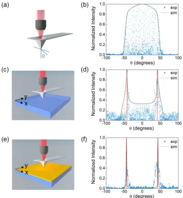
Figure 4 displays the far-field radiation patterns of the scat-tered light with the aperture tip placed in air (Figure 4.a.), and in contact with the transparent and metallic film sam-ples (Figures 4.c. and 4.e.). The normalized intensity is plot-ted against the emission angle in Figures 4.b., 4.d. and 4.f. respectively. The experimental scatter plots (blue) are ob-tained by first transforming into spherical coordinates the raw data of the electromagnetic field intensity obtained from the hologram after 3D reconstruction. Then, we select the values contained in the x-z plane of the NSOM tip perpen-dicular to the sample surface, and in a spherical slice of thickness Δρ = 30 nm centered on the aperture tip. This thickness is chosen in such a way that one intensity value at most is attributed to each angle θ in the resulting data selec-tion. The black plots correspond to the simulated radiation patterns of the superposition of a My dipole and a Px dipole
the experimental results. The vertical red lines indicate the position of the critical angle (Figure 4.d.) and the emission angle (Figure 4.f.). For the tip placed in free space, broad angular distribution centered around is observed with the intensity decaying mo-notonously on both sides of the maximum (Figure 4.b.). For the glass sample, we confirm that light emerges through the substrate at maximum angles of when the tip is in contact with the surface, in addition to forward scattering beneath the aperture tip centered around (Figure 4.d.). However, when the aperture tip is in contact with the metallic film (Figure 4.f), scattered light forms two narrow peaks at corresponding to the surface plasmons that are excited at the metal/air interface and tunnel through the film before leaking into the glass substrate. It occurs be-yond the critical angle of a glass/air interface
. Its detection is experimentally possible thanks to the high numerical aperture of the oil objective used for collection (see Measurement section).
We then carry out measurements where the tip is placed at a height of 3 µm above the metallic film sample, which allows us to compare the angular radiation patterns of the scattered light when the tip is placed both in the near-field (Figures 4.e and 4.f.) and far-field regions (Figure 5). We can infer that when the tip is off-contact (Figure 5.b.), the gold film has no significant effect on the scattering angle. The maximum in-tensity of the far-field radiation pattern at ρ = 10 µm is re-duced by a factor 2.5 when the aperture tip is out of contact at a height of 3 µm, due to the poor transmission of the gold film. At this height, the large lateral wavevector components produced at the sub-λ aperture tip are significantly sup-pressed, which hinders the efficient excitation of surface plasmons on the gold film. As a result, emission remains below and exhibits two maxima at ±40.5°, which is similar to the observation made when the tip is placed 3 µm above the glass substrate without metallic film (not shown). These results are consistent with previous measurements by Hecht et al.2 based on the combination of back-focal plane
and real space imaging. For completitude, we show in Figure S.2. (see Supporting Information) the x-z section view of the wavefront reconstruction obtained experimentally when the tip is 3 µm above the metallic film, for comparison with the situation where it is in contact with it (Figure 3.k).
Figure 4. Far-field radiation patterns of light scattered by a NSOM tip placed in (a) free space, and in contact with (c) a transparent glass substrate, and (e) a 40 nm gold film on a glass substrate. (b,d,f) Normalized intensity versus the emis-sion angle in the x-z plan of the NSOM tip for the three cases (a, c, e). The vertical red lines in (d) correspond to the position of the critical angle = 41.8°, and those in (f) correspond the emission angle = 43.3°.
Figure 5. Far-field radiation patterns of scattered light through a 40 nm gold film on a glass substrate from a NSOM tip placed at 3 µm above the sample surface (a). (b) Normal-ized intensity versus the emission angle in the x-z plan of the NSOM tip. Experimental data are plotted in blue and FDTD simulations in black. The vertical red line corresponds to the position of the resonance angle of excitation of leaky surface plasmons = 43.3°.
In summary, a full-field off-axis holography technique adapted on a NSOM setup provides an accurate three-dimensional reconstruction of light scattered from its tip in near-field interaction with the environment. After a numerical Fourier analysis of the recorded hologram, the amplitude and phase of the EM field can be calculated at any plane away from the source, which is a crucial infor-mation to fully characterize the tip and overcome the limitations of the NSOM approach. This method is
ap-plied here to reconstruct in 3D a tomographic image of the scattered light from the metal-coated hollow pyrami-dal aperture tip of a NSOM in free space and coupled to transparent and plasmonic media. FDTD simulations show good agreement with the experimental results, and indicate that such hollow pyramidal probes can be mod-eled as a superposition of magnetic and electric dipoles perpendicular to each other in the plane of the aperture.
With the DHM/NSOM hybrid system, we have shown that the coupling of a NSOM tip to the environment has a dramatic influence on the way it scatters light. Combined with nanolithography and nanomanipulation techniques, NSOM provides a unique way to tune the interaction be-tween nanostructures by performing a fine adjustment of their relative position. The high versatility of the instru-ment combined with DHM reconstruction methods should allow one to study in detail coupled EM resonators or complex systems involving multiple scattering events. Mapping the phase in 3D could also be of high interest in some of these studies, beyond using it to back-propagate numerically the EM field towards the source to obtain a 3D reconstruction of the EM field intensity as we have done here.
All measurements are performed by an optical setup composed of a Mach-Zehnder off-axis interfer-ometer combined with a modified commercial NSOM (WITec GmbH alpha300S). A 90-10 fiber splitter is used to split the light coming from a single mode He-Ne laser (Re-search Electro Optics R-32413, λ=633 nm, P=35 mW) into the sample and reference beams. The sample beam is focused through a 20x, NA=0.4 objective on the apex of a 150 nm SiO2
pyramidal aperture probe coated with 120 nm of Al, with a cone angle of ~70 degrees. The sample is placed on a three-axis stage, and the distance between the sample and the tip is controlled by a piezoelectric positioner. The scattered light is collected by a 100x, NA = 0.9 objective when tip is in free space, and by a 100x, NA = 1.4 oil objective in the presence of a sample. It is then directed to a CCD camera (Photon Focus MV-D1024E-160-CL, sensor resolution: 1024×1024, 8 μm×8 μm pixel matrix, 0.2 sec exposure time) for holography re-cordings. A polarizer and a half-wave plate are placed in the path of both the sample and reference beams to ensure that the incident light on the NSOM probe is linearly polarized and that a maximum contrast is attained. The reconstruction procedure is carried out by a fast Fourier transform (FTT) algorithm that performs a Fourier transform of the recorded hologram, allowing spatial filtering of the unwanted diffrac-tion orders to reduce the noise, and then propagates the complex field towards the source.
The transparent sample is made of a 160 µm glass coverslip (VWR Micro Cover Glasses, No. 1). The plas-monic sample is made of a 40 nm gold film evaporated on an identical glass coverslip.
Simulations are performed using the Finite Difference Time Domain (FDTD) method (Lumerical Solu-tions Inc). A tangential lateral magnetic dipole Hy and an
electric dipole Ex of strengths 2 and 1, respectively, are placed
perpendicular to each other in air, and at various distances
from a 200 μm wide substrate. A frequency-domain field monitor, used to collect the field profile in the frequency domain, is placed in the x-z plane at the position of the NSOM tip to record the electromagnetic intensity of the transmitted light up to a distance of 10 µm below the dipole sources. Another monitor is placed exactly at below the dipoles to evaluate the far-field projection of the trans-mitted radiation by Fourier transform calculations. Perfectly matched layer (PML) absorbing boundary conditions (32 PML layers) that are impedance matched to the simulation region and its materials are used. The value of the complex permittivity of gold is at 633 nm, taken from Olmon et al.30.
The supporting information shows cross sections in the x-y plane of the reconstructed scattered field intensity measured on the sample made of a metallic film on glass (Figure S1), and a x-z section view of the wavefront recon-struction obtained when the tip is 3 µm above the metal-lic film (Figure S2).
* Emails: [email protected], [email protected]
This research was supported by LABEX WIFI (Laboratory of Excellence within the French Program Investments for the Future) under references LABX-24 and ANR-10-IDEX-0001-02 PSL*, and Agence Nationale de la Recherche (ANR), Project CarISOVERRE, ANR-16-CE09-0012.
The authors thank Mathias Fink, Arthur Goetschy and Ro-man Pierrat, from the Institut Langevin for stimulating dis-cussions and constructive comments.
(1) Pohl, D. W.; Denk, W.; Lanz, M. Optical Stethoscopy: Image Recording with Resolution λ/20. Appl. Phys. Lett. 1984, 44 (7), 651–653.
(2) Hecht, B.; Bielefeldt, H.; Novotny, L.; Inouye, Y.; Pohl, D. W. Local Excitation, Scattering, and Interference of Surface Plasmons. Phys. Rev. Lett. 1996, 77 (9), 1889–1892.
(3) Bharadwaj, P.; Bouhelier, A.; Novotny, L. Electrical Excitation of Surface Plasmons. Phys. Rev. Lett. 2011, 106 (22), 226802.
(4) Marty, R.; Girard, C.; Arbouet, A.; Colas des Francs, G. Near-Field Coupling of a Point-like Dipolar Source with a Thin Metallic Film: Implication for STM Plasmon Excitations. Chem.
Phys. Lett. 2012, 532, 100–105.
(5) Drezet, A.; Genet, C. Imaging Surface Plasmons: From Leaky Waves to Far-Field Radiation. Phys. Rev. Lett. 2013, 110 (21), 213901.
(6) Novotny, L.; Hecht, B. Principles of Nano-Optics; Cam-bridge university press, 2012.
(7) Sánchez, E. J.; Novotny, L.; Xie, X. S. Near-Field Fluo-rescence Microscopy Based on Two-Photon Excitation with Met-al Tips. Phys. Rev. Lett. 1999, 82 (20), 4014.
(8) Greffet, J.-J.; Carminati, R. Image Formation in near-Field Optics. Prog. Surf. Sci. 1997, 56 (3), 133–237.
(9) Bethe, H. A. Theory of Diffraction by Small Holes.
Phys. Rev. 1944, 66 (7–8), 163.
(10) Obermüller, C.; Karrai, K. Far Field Characterization of Diffracting Circular Apertures. Appl. Phys. Lett. 1995, 67 (23), 3408–3410.
(11) Obermüller, C.; Karrai, K.; Kolb, G.; Abstreiter, G. Transmitted Radiation through a Subwavelength-Sized Tapered Optical Fiber Tip. Ultramicroscopy 1995, 61 (1), 171–177.
(12) Drezet, A.; Woehl, J. C.; Huant, S. Diffraction by a Small Aperture in Conical Geometry: Application to Metal-Coated Tips Used in near-Field Scanning Optical Microscopy.
Phys. Rev. E 2002, 65 (4).
(13) Drezet, A.; Woehl, J. C.; Huant, S. Extension of Bethe’s Diffraction Model to Conical Geometry: Application to near-Field Optics. Europhys. Lett. 2001, 54 (6), 736.
(14) Drezet, A.; Cuche, A.; Huant, S. Near-Field Microscopy with a Single-Photon Point-like Emitter: Resolution versus the Aperture Tip? Opt. Commun. 2011, 284 (5), 1444–1450.
(15) Denkova, D.; Verellen, N.; Silhanek, A. V.; Valev, V. K.; Dorpe, P. V.; Moshchalkov, V. V. Mapping Magnetic Near-Field Distributions of Plasmonic Nanoantennas. ACS Nano 2013, 7 (4), 3168–3176.
(16) Curto, A. G.; Volpe, G.; Taminiau, T. H.; Kreuzer, M. P.; Quidant, R.; Hulst, N. F. van. Unidirectional Emission of a Quan-tum Dot Coupled to a Nanoantenna. Science 2010, 329 (5994), 930–933.
(17) Xie, Z.; Lefier, Y.; Suarez, M. A.; Mivelle, M.; Salut, R.; Merolla, J.-M.; Grosjean, T. Doubly Resonant Photonic Antenna for Single Infrared Quantum Dot Imaging at Telecommunication Wavelengths. Nano Lett. 2017, 17 (4), 2152–2158.
(18) Thomas, M.; Greffet, J. J.; Carminati, R.; Arias-Gonzalez, J. R. Single-Molecule Spontaneous Emission close to Absorbing Nanostructures. Appl. Phys. Lett. 2004, 85 (17), 3863– 3865.
(19) Babuty, A.; Joulain, K.; Chapuis, P.-O.; Greffet, J.-J.; De Wilde, Y. Blackbody Spectrum Revisited in the Near Field. Phys.
Rev. Lett. 2013, 110 (14), 146103.
(20) Joulain, K.; Ben-Abdallah, P.; Chapuis, P.-O.; De Wilde, Y.; Babuty, A.; Henkel, C. Strong Tip–sample Coupling in
Ther-mal Radiation Scanning Tunneling Microscopy. J. Quant.
Spec-trosc. Radiat. Transf. 2014, 136 (Supplement C), 1–15.
(21) Drezet, A.; Hohenau, A.; Koller, D.; Stepanov, A.; Ditlbacher, H.; Steinberger, B.; Aussenegg, F. R.; Leitner, A.; Krenn, J. R. Leakage Radiation Microscopy of Surface Plasmon Polaritons. Mater. Sci. Eng. B 2008, 149 (3), 220–229.
(22) Berthel, M.; Jiang, Q.; Pham, A.; Bellessa, J.; Genet, C.; Huant, S.; Drezet, A. Directional Local Density of States of Clas-sical and Quantum Propagating Surface Plasmons. Phys. Rev.
Appl. 2017, 7 (1), 14021.
(23) Lieb, M. A.; Zavislan, J. M.; Novotny, L. Single-Molecule Orientations Determined by Direct Emission Pattern Imaging. JOSA B 2004, 21 (6), 1210–1215.
(24) Cuche, E.; Marquet, P.; Depeursinge, C. Spatial Filter-ing for Zero-Order and Twin-Image Elimination in Digital off-Axis Holography. Appl. Opt. 2000, 39 (23), 4070–4075.
(25) Suck, S. Y.; Collin, S.; Bardou, N.; De Wilde, Y.; Tessier, G. Imaging the Three-Dimensional Scattering Pattern of Plas-monic Nanodisk Chains by Digital Heterodyne Holography. Opt.
Lett. 2011, 36 (6), 849–851.
(26) Park, C.; Park, J.-H.; Rodriguez, C.; Yu, H.; Kim, M.; Jin, K.; Han, S.; Shin, J.; Ko, S. H.; Nam, K. T.; et al. Full-Field Sub-wavelength Imaging Using a Scattering Superlens. Phys. Rev.
Lett. 2014, 113 (11).
(27) Parigi, V.; Perros, E.; Binard, G.; Bourdillon, C.; Maître, A.; Carminati, R.; Krachmalnicoff, V.; Wilde, Y. D. Near-Field to Far-Field Characterization of Speckle Patterns Generated by Disordered Nanomaterials. Opt. Express 2016, 24 (7), 7019–7027. (28) Witec GmbH www.witec.de.
(29) VWR International - Chemicals and Laboratory Scien-tific Supplies www.vwr.com.
(30) Olmon, R. L.; Slovick, B.; Johnson, T. W.; Shelton, D.; Oh, S.-H.; Boreman, G. D.; Raschke, M. B. Optical Dielectric Function of Gold. Phys. Rev. B 2012, 86 (23), 235147.
(31) Wang, B.; Aigouy, L.; Bourhis, E.; Gierak, J.; Hugonin, J. P.; Lalanne, P. Efficient Generation of Surface Plasmon by Sin-gle-Nanoslit Illumination under Highly Oblique Incidence. Appl.