HAL Id: hal-01651826
https://hal.archives-ouvertes.fr/hal-01651826
Submitted on 29 Nov 2017
HAL is a multi-disciplinary open access
archive for the deposit and dissemination of
sci-entific research documents, whether they are
pub-lished or not. The documents may come from
teaching and research institutions in France or
abroad, or from public or private research centers.
L’archive ouverte pluridisciplinaire HAL, est
destinée au dépôt et à la diffusion de documents
scientifiques de niveau recherche, publiés ou non,
émanant des établissements d’enseignement et de
recherche français ou étrangers, des laboratoires
publics ou privés.
Engineering n-p junction for photo-electrochemical
hydrogen production.
Toupin J., H. Strub, S. Kressmann, M. Boudot, V. Artero, Ch.
Laberty-Robert
To cite this version:
Toupin J., H. Strub, S. Kressmann, M. Boudot, V. Artero, et al.. Engineering n-p junction for
photo-electrochemical hydrogen production.. Physical Chemistry Chemical Physics, Royal Society of
Chemistry, 2017, 45 (19), pp.30675-30682. �10.1039/c7cp05122k�. �hal-01651826�
Engineering n-p junction for photo-electrochemical
hydrogen production
J. Toupina,b,c, H. Strubb, S. Kressmannb, M. Boudota, V. Arteroc and Ch. Laberty-Roberta*
The generation of hydrogen from water and sunlight offers a promising approach for producing scalable and sustainable carbon free fuels. One of the challenges of solar-to-fuel technology is the design of efficient, longlasting and low-cost photocathodes, which are responsible for absorbing sunlight and driving catalytic hydrogen evolution. We report on the protection of a Cu/Cu2O/CuO photoelectrode against photocorrosion by a 200-300 nm-thick BaTiO3 perovskite layer,
deposited using the sol-gel method. This photoelectrode mediates H2 production with a current density of 3.1 mA.cm-2
at 0 V versus RHE under 3 sun irradiation and in pH = 6 aqueous electrolyte. While unprotected Cu/Cu2O/CuO
photoelectrodes show a rapid decay of activity, the BaTiO3-protected photoelectrodes exhibit 10% current decay over
20 min.
A. Introduction
Concerns over climate change resulting from accumulation of anthropogenic carbon dioxide in the atmosphere and the uncertainty in the amount of recoverable fossil fuels reserves are driving forces for the development of renewable, carbon-neutral energy technologies. The production of hydrogen from water and sunlight in photoelectrochemical cells (PECs) is an appealing technology for producing a scalable and sustainable carbon-free fuel.1 To design efficient PECs, one of the challenges is the availability of earthabundant semiconducting photoelectrode materials that absorb sunlight and drive the two water splitting half-reactions 2.Up to now, a large number of photoelectrode materials, including metal oxides and other chalchogenides or group III-V semiconductors, have been explored. Significant improvements on the solar-to-hydrogen efficiency have been reported3 but not a single material has yet been found that simultaneously satisfies both efficiency, cost-effectiveness and stability required to widespread the photoelectrochemical technology.4, 5, 6 Cu2O is a promising
photocathode material due to its suitable band gap (1.9 – 2.2 eV), high absorption coefficient in the visible range
7,8,9,10,11
and theoretical photocurrent of 14.7 mA.cm2.12 Its conduction band is located cathodic to the reduction potential of water, making it suitable for mediating H2
production in a PEC cell. Among different synthesis methods tested, electrodeposition has been proven to be the most convenient and reliable to prepare nanostructured Cu2O.13, 14,15, 16, 17
Indeed, Cu2O morphology and orientation can be
tuned by judiciously setting deposition parameters such as the electrolyte pH, temperature, applied potential and current density. Controlling the morphology and crystal structure of the electrodes allows enhancing their performances that mainly rely on their light absorption and charge transport properties.
Although Cu2O possesses an intrinsic potential as a
photocathode, the reported photocurrents remain far below the theoretical values. These poor performances arise essentially from structural defects at the semiconductor-electrolyte interface. Indeed, at low applied potentials, Cu2O
does not transfer electrons efficiently toward the electrolyte due to an inappropriate band bending. Additionally, Cu2O
suffers from reduction to Cu under irradiation in aqueous
solutions, because of the positioning of the redox potentials of the Cu2O/Cu couple within the band-gap. 12, 18 This latter
limits both the efficiency and lifetime of copper-based photocathodes. Extensive efforts have then been directed toward the development of architectures that integrate heterojunctions, catalysts and protective insulating layers,12 with the aim at improving the stability and solar-to-hydrogen conversion efficiency. Building heterojunction structures with other semiconductors, such as CuO/ZnO,19 CuO/TiO2,20
Cu2O/TiO2,21 for efficient separation of photogenerated
electronhole pairs indeed improved the performance of the photoelectrodes and their stability. Among the various heterojunction studied, the Cu2O/CuO heterojunction proved
to be particularly promising. CuO is a ptype oxide for photoelectrochemical hydrogen production with a direct bandgap of 1.3 1.7 eV, depending on the preparation methods and conditions.22, 23, 24 In the Cu2O/CuO
heterojunction, the electrons photogenerated in Cu2O will
flow toward CuO because the conduction band edge of CuO is at lower potential than the one of Cu2O.25 Reported
Cu2O/CuO photocathode indeed exhibited photocurrent
density for hydrogen evolution of 3.15 mA.cm-2 at 0.4 V vs. RHE, which was one of the highest reported at this potential on copper-oxide-based photocathodes.26 The high photoactivity of these electrodes was ascribed to i) the broadened light absorption band due to combined absorption by CuO and Cu2O that harvest more solar energy,
ii) the large depletion region that enhances electron-hole separation, and iii) the high majority charge carrier density that ensures a faster charge transportation rate.
In this paper, we report on the use of electrodeposition to synthesize Cu/Cu2O/CuO photoelectrodes and on the
amelioration of their stability through the deposition of a thin layer of ntype largebandgap oxide semiconductor. First, the protection of our Cu/Cu2O/CuO photoelectrodes
was performed by the deposition of TiO2 thin layer. This layer
induces a decrease of the photo electrochemical activity of our copper based photoelectrodes but with an increase of their stability, demonstrating the interest of such an approach. We then changed our strategy to deposit a thin layer of BaTiO3 by solgel chemistry coupled with
dipcoating technique. BaTiO3 appears to be an interesting
tunneling junction for charge transport due to a favorable band alignment.
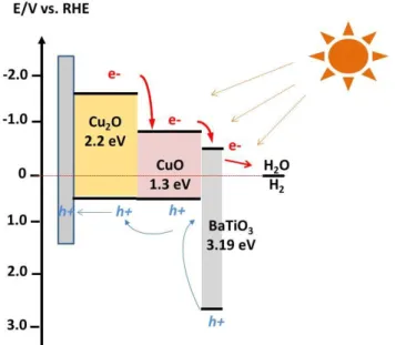
Figure 1. Energy level scheme of the BaTiO3protected
copper based photocathode at pH = 0. At the photocathode, protons are reduced to hydrogen by the photogenerated electrons. The scheme illustrates the generation and transport of the charge carriers, and highlights the minimum conduction-band offset between BaTiO3 and copper oxides,
needed for electrons to be transported across the protection layer.
Compared to TiO2, the edge of its conduction band (-0.5 V vs
RHE, determined through Mott-Schottky measurement, data not shown 27) is indeed closer to that of CuO, favoring electron transport thanks to a more favorable band alignment and providing more driving force for hydrogen evolution at the electrode surface. These combined effects enhance the photoelectrochemical activity while photocorrosion damages are limited since contact of the aqueous electrolyte with the copperbased photoelectrodes is avoided. The Cu/Cu2O/CuO/BaTiO3 photocathodes
revealed to be quite stable with little degradation observed at 0 V vs RHE after 20 min of illumination at pH = 6 (about 10% of degradation). A photocurrent of 3.1 mA.cm2 was measured, which rank these architectures among the best copper-based photoelectrodes for hydrogen evolution. B. Experimental
Synthetic procedures Cu electrodeposition.
The copper films were deposited by electrodeposition from an acid solution of copper sulphate. The deposition substrate (working electrode) was fluorine-doped tin oxide (FTO, Asahi 80 Solems). The FTO substrates were first conditioned during 1020 s under cathodic current (-25 mA/cm2) in a solution made of 0.01 M of Na2SO4.10H2O and 0.1 M of H2SO4. This
pre-treatment was necessary to achieve better substrate adhesion of the electrodes and reproducibility. 21 The plating bath was 0.8 M Cu(SO4) and 0.45 M H2SO4 in deionized water
at ambient temperature. The Cu films were deposited at a
constant current density ( 220 mA/cm2, galvanostatic mode)
using a biologic potentiostat in a three-electrode configuration (a copper electrode served as the counter electrode and Ag/AgCl served as reference electrode), which resulted in a film of several m thickness. During this step, because of the current applied, the formation of H2 occurs.
Lately, these H2 bubbles bounded at the surface are covered
by copper and the resulting film is made of empty spheres bounded to each other. This morphology is kept after the anodization step, during which Cu is transformed into Cu(OH)2 and CuO, the heat treatment and the deposition of
BaTiO3.
Anodization. The anodization solution consisted of aqueous NaOH (1 M) and anodization was performed at 3 mA/cm2 in a threeelectrode configuration.
CuO formation. Heat treatment was finally achieved at 450°C in the air for 30 to transform Cu(OH)2 into CuO.
TiO2 deposition. TiO2 was deposited using the sol-gel and
dip-coating methods. First, a Ti5E solution was prepared by mixing 19g of TiCl4 and 23 g of absolute ethanol. This
solution is then mixed with 5.7 g of absolute ethanol and deposited onto the FTO/Cu/Cu2O/CuO substrate with a
withdrawal speed of 2.5 mm/s. A heat treatment at 400°C for 1 min under air is applied between each layer and the final treatment is 500°C for 1 h in air.
BaTiO3 deposition. BaTiO3 was deposited using the sol-gel
and dip-coating methods. The sol-gel solution is made of 1.42 g Ba(OH)2.7H2O (Sigma Aldrich) and 1.36 g of titanium
isopropoxide (sigma Aldrich) in acetylacetone (0.36g), glacial acetic acid (6g) and ethanol (9g). Pluronic® F127 (0.28 g) was added to the previous solution to obtain homogenous film. The FTO/Cu/Cu2O/CuO substrate was dipped into the sol-gel solution and then removed at 2.5 mm/s; to increase the thickness of the BaTiO3 film, several layers (two layers) have
been deposited. In that case, the films were placed for 60 min in a furnace preheated at 350°C before a new layer is deposited. Final heattreatment in the air at 600°C for 15 min was applied.
Structural characterization. The morphology of the films was characterized using a high-resolution scanning electron microscope (Hitachi SU70). XRD patterns were acquired with a Bruker D8 Discover diffractometer in the Bragg-Brentano mode, using Cu K radiation (1.540598Å) and a Ni -filter. Spectra were acquired with a 1D Lynxeye detector from 2 = 20° 80° at a step width of 0.05° with acquisition time of 1 s and a source slit width of 4mm.
Photoelectrochemical measurements. The photoelectroche mical performances of the electrodes were evaluated in a three-electrode configuration under frontside light illumination using a Solartron Ametek 2087A Potentiostat / Galvanostat / impedancemeter. The
electrolyte was a 1.0 M Na2SO4 solution buffered at pH 6
with potassium phosphate (0.1 M). The reference electrode was Ag/AgCl in saturated KCl, and a Pt wire was used as the counter electrode. The photoresponse was measured under chopped irradiation from a 280 W Xe lamp equipped with an ultraviolet filter (Oriel 51272, 400nm) and IR radiation ( > 950 nm) filter. The light intensity was measured with 1918-R Newport power meter 918D-UVOD3R,UV Silicon Detector
(200 – 1100 nm) and estimated to 3 suns (240 mW.cm-2, visible-IR irradiation).28 The scan rate for the linear sweep voltammetry measurements was 20 mV s−1. Impedance spectroscopy measurements have been performed using the following parameters: frequency range (200 kHz – 0.1 Hz) at 0 V vs. RHE at pH = 6. The E is 20 mV. Mott-Schottky diagrams were obtained from measurements performed in pH 14 NaOH electrolyte. The potential varied between -1.5 V and 2.6 V vs. RHE and the measurement was performed at 1 kHz. Photocurrent stability tests were carried out by measuring the photocurrent produced under chopped light irradiation (0.1 Hz light/dark cycles frequency) at a fixed potential of 0 V versus RHE. During linear sweep voltammetry (j–V plots) and chronoamperometry (stability plots) the electrolyte was continuously bubbled with N2 to
remove oxygen and thus eliminate erroneous signals arising from oxygen reduction.
Stability and faradic measurements were tested in a laboratory fabricated air tight H-cell with a plastic window allowing a 3-electrode setup, with the reference and counter electrodes separated by glass frits from the main compartment. Hydrogen in the headspace of the cell was detected with a Perkin Elmer Clarus 580 gas chromatograph equipped with a TCD and nitrogen carrier gas operating at 32°C. For H2 detection, the electrochemical cell used was gas
tight and no mixture between gas formed at the working electrode and the counter electrode was possible.
UVvisible absorption spectra were measured using an Agilent Technologies Cary Series spectrophotometer. C. Results and Discussion
Synthesis and characterization of Cu/Cu2O/CuO
photoelectrodes.
The Cu/Cu2O/CuO photoelectrodes used in this study were
prepared by electrodeposition of copper metal followed by an anodization process and a calcination step at 450°C in the air. The details of the procedure are described in the experimental section. The currents applied during the cathodic electrodeposition and anodization steps were chosen at 20 mA.cm-2 and +3 mA.cm-2, respectively. For the sake of simplicity, the Cu/Cu2O/CuO photoelectrodes were
named EA X-Y where X is the duration of electrodeposition and Y is the duration of anodization (X and Y are expressed in min.). Anodization simultaneously produces Cu2O and
Cu(OH)2. The films are blue which is characteristic of the
presence of Cu(OH)2. Calcination at 450°C in the air was then
performed to transform Cu(OH)2 into CuO. During this step,
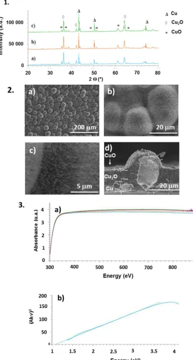
the colour of the films evolves from blue to dark grey/black. XRD patterns obtained for photoelectrodes with different anodization and electrodeposited times are reported in Figure 2.1.
Figure 2. X-rays diffraction patterns, particle morphology and optical property of Cu/Cu2O/CuO films. 1) Xrays diffraction
patterns of EA 5-5 (a), EA 10-5 (b) and EA 15-5 (c) photoelectrodes; 2) SEM images of EA 2020 photoelectrodes (a-c) and crosssection image for EA 5-10 photoelectrode (d); 3) UV-visible absorbance (a) for EA 5-15 (blue), EA 10-15 (orange), EA 1515 (green) and EA 1020 (purple) photoelectrodes and TAUC plot (b) for EA 1515.
Table 1. Cu, Cu2O and CuO crystallite size (in nm with error of
10 nm) for photoelectrodes synthesized under various conditions. Compounds EA 5-5 EA 5-10 EA 10-5 EA 10-15 EA 15-5 Cu 113 115 103 120 106 Cu2O 24 25 26 22 24 CuO 20 35 29 28 20
These XRD patterns confirm the coexistence of Cu, Cu2O and
CuO. We notice that the intensity of peaks relative to copper increases with the electrodeposition time while the ratio between the intensity of peaks corresponding to copper oxides (Cu2O and CuO) augments with the anodization time.
Furthermore, the electrodeposited copper layer exhibits preferential (111) and (200) orientations, 29, 30,31 which impacts the growth direction of Cu2O oxides. Indeed, Cu2O
oxide exhibits a preferential (111) orientation, which has been shown to have a low resistivity with a concentration of charge almost twice as high as (100) orientation. 32 The crystallite size was estimated from XRD patterns using DebyeScherrer formula and estimated to 100 nm for Cu,
24 nm for Cu2O and 31 nm for CuO. The electrodeposited
and anodization times do not influence the particle size as shown in Table 1.
Scanning electron microscopy (SEM) images (Figure 2.2) indicate that the surface of the electrode is a continuous layer embedding spheres with several m diameters. Cross section images show that the core of the sphere is empty, which is likely due to the formation of H2 bubbles during
copper electrodeposition. Furthermore, these spheres exhibit thin needles at their surface. Crosssection analyses indicated that the film was composed of three layers: metallic copper, Cu2O and CuO. The same layers were
noticed within the shell of the spheres as well. The dependence of the thickness of the three layers on the current density used during synthesis was studied by analysing cross-section SEM images. It appeared that the thicknesses of CuO (1 m) layer remain the same whatever the electrodeposition and the anodization time. The thickness of the Cu layer linearly depends on the time of electrodeposition. Increasing the anodization time leads to thicker Cu2O film. The combined thickness of these three
different layers was estimated to 20 m for EA 2020 photoelectrodes. The needles' formation was assigned to the oxidation reaction at the Cu2O/CuO interface that induces a
compressive stress in the CuO layer favouring the diffusion of copper along the CuO grain boundaries. 32, 33 The CuO film then acts as a substrate for the growth of CuO needles. This mechanism starts when the CuO layer is about 1 m thick and leads to CuO needles which are several m long.
The ultravioletvisible (UV) diffuse reflectance spectrum (figure 2.3) indicated that the dark Cu/Cu2O/Cu films absorb
solar energy for wavelengths higher than 350 nm whatever the experimental conditions used for their synthesis. Further analysis of the absorption spectrum revealed a direct
bandgap of 1.1 eV. This latter is slightly lower than the values reported for CuO (1.3-1.9 eV).
Linear sweep voltammetry in the dark and under choppedlight irradiation conditions was used to investigate the effect of the experimental conditions used for the synthesis of the photoelectrodes on the current density at pH = 6 (Figure 3 and Table 2).
Table 2. Current density measured at 0 V vs. RHE from IV
curves and pH = 6 under 3 sun visiblelight irradiation for copperbased photoelectrodes produced with different synthesis conditions.
Electrode EA15-15 EA20-20 EA30-30
Current density (mA.cm-2)
-2.7 -4.3 -3.2
Figure 3. Current density versus potential curves for the EA 2020 Cu/Cu2O/CuO electrode at pH = 6 under a 3 sun
visible-light chopped irradiation.
Cathodic photocurrents confirm that these films behave as ptype semiconductor. The onset photocurrent potential is
0.4 V versus RHE indicating that these electrodes can be practically used as photocathodes in the context of photo-electrochemical watersplitting.
Table 2 summarizes photo-electrochemical performances of Cu/Cu2O/CuO electrodes synthesized with different
anodization and electrodeposition times. High photocurrents values ranging between - 2.7 mA.cm-2 and - 4.3 mA.cm-2 are obtained at 0 V vs. RHE and pH = 6. The best result are obtained for anodization and electrodeposition times of 20 min. Increasing those times, and therefore the thickness of the Cu2O layer, did not improve photocurrent values above
4.3 mA.cm-2 at 0V vs RHE, pH = 6. Indeed, the depth of penetration of light in the electrode can be estimated between 4 m and 10 m, depending on the synthesis parameters, from the absorbance study and the electrode thickness. Whatever the experimental synthetic conditions used, these values are lower than the thickness of both CuO and Cu2O layers ( > 15 m), indicating that the maximum
photocurrent measured correspond to optimal light harvesting by the photoelectrode.
Stability measurements were conducted using chronoamperometry measurements at 0 V vs. RHE. As shown in Figure 4, degradation readily occurs after 20 min of operation, which suggests photocorrosion of CuO and Cu2O
layers.
Figure 4. Chronoamperometry measurements at 0 V vs. RHE and pH = 6 for different Cu/Cu2O/CuO photoelectrodes
under chopped visible-light irradiation (3 sun): EA 1515 (blue); EA 2020 (orange); EA 2525 (green) and EA 3030 (purple).
Synthesis and Characterization of Cubased photoelectrodeBaTiO3.
The protection of Cu/Cu2O/CuO photoelectrodes by BaTiO3
was then investigated in order to achieve stable current. The BaTiO3 perovskite material was selected because of its
ntype character suitable for fabricating a pn junction together with its conduction band edge potential slightly positive to the one of CuO and Cu2O, still negative to the H2
evolution potential (Figure 1). Furthermore, BaTiO3 is stable
in aqueous solution over a large range of pH. 34
The procedure to fabricate the Cu-based photoelectrodes protected by BaTiO3 is detailed in the experimental section.
Several layers (at least 2) were necessary to cover uniformly the rough surface of the Cu/Cu2O/CuO photoelectrodes and
a final heattreatment at 600°C in the air was applied to crystallize the perovskite film. XRD patterns measured before and after the BaTiO3 solgel deposition confirm the presence
of the perovskite phase (Figure 5.1). The intensity of the BaTiO3 peaks is low compared to the ones corresponding to
Cu2O and CuO, indicating that the thickness of the protective
layer is low (i.e. 200-300 nm). Note that the CuO/Cu ratio is different in electrode without and with BaTiO3 layer. There is
more CuO for electrode with BaTiO3 layer. Probably, it has
been formed during the deposition of the perovskite layer, in oxidizing atmosphere at high temperature (600°C).
The BaTiO3 film was deposited, for the first time, on top of
the Cu/Cu2O/CuO photoelectrodes by the solgel method
coupled with the dipcoating process.
Figure 5. Structural characterization, particle morphology and optical properties of Cu/Cu2O/CuO/BaTiO3
photoelectrodes. 1) Xrays diffraction patterns of electrodes without (a) and with (b) BaTiO3 protecting layer; the inset is a
magnification of trace (b) with the presence of BaTiO3
marked by the black point; 2) SEM images of the BaTiO3protected electrodes.
This is confirmed by crosssection SEM analyses (see Figure 5.2). The thickness of the BaTiO3 layer was estimated to be
200300 nm while the CuO and Cu2O layers are 12 m and
15 m thick, respectively. Note that the thickness of the Cu2O layer is augmented in comparison with the bare
electrode. This is due to the heat treatment in the air at 600°C needed for the synthesis of BaTiO3 that partly converts
Cu into Cu2O. Otherwise, a comparison of the microstructure
of the electrode before and after BaTiO3 deposition indicated
that the microstructure of the Cu/Cu2O/CuO
photoelectrodes remains unchanged, except for the ratio Cu/Cu2O/CuO ratio and the presence of the thin layer of
BaTiO3 on top of the photoelectrodes. The UVvisible diffuse
reflectance spectra (Figure SI.1)) are similar to those observed for Cu/Cu2O/CuO electrodes. A slight increase of
the absorbance was observed in the UV region due to the presence of BaTiO3 exhibiting a band gap of 3.8 eV. The TAUC
plot indicates a bandgap of 1.1 eV which is in agreement with the values measured previously onto the bare electrodes. EDX analyses indicated a Ba/Ti ratio of 1, confirming the presence and stoichiometry of perovskite BaTiO3.
The photoelectrochemical performances of surfaceprotected electrodes were evaluated under 3 sun visible-light irradiation and Table 2 summarizes the results. In this Table, the photocurrent values refer to the value measured at 0 V versus RHE during the linear sweep voltammetry (jV plot, Figure 6) under chopped illumination.
Table 2. Current density measured at 0 V vs. RHE from I-V curves and pH = 6 under 3 sun visiblelight irradiation for copper-based photoelectrodes produced with different synthesis conditions.
Electrode EA15-15 EA20-20 EA30-30
- BaTiO3 - BaTiO3 - BaTiO3
Current density (mA.cm-2)
-2.2 - 2.5 - 2.5 - 3.1 - 3.3 - 3.0
Photocurrent values ranging between - 2.5 and - 3.1 mA.cm-2 at 0 V vs RHE at pH = 6 are obtained, slightly higher than the ones measured for the bare Cu/Cu2O/CuO photoelectrodes
prepared with the same procedure. Note that for this study the bare electrodes have received a heat-treatment at 600°C under air, treatment used when BaTiO3 is deposited ontop of
the Cu/Cu2O/CuO photoelectrodes. As a consequence, the
photocurrents are slightly lower than those measured on the previous set of values due to the difference of the Cu/Cu2O/CuO ratio.
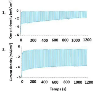
The stability of the photocurrent was then evaluated through chronoamperometric measurements performed at 0 V versus RHE under chopped light over 20 min at pH = 6. Figure 7 summarizes the results obtained on bare and BaTiO3protected electrodes.
Figure 6. Photo electrochemical response for BaTiO3protected electrodes. Currentpotential
characteristics at pH = 6, under chopped light illumination (visible light, 3 sun) for BaTiO3-protected (blue) and bare
(orange) EA 2020 Cu/Cu2O/CuO photoelectrodes.
Bare Cu/Cu2O/CuO, although exhibiting a large photocurrent
in the first minutes as reported before, 34, 35 unsurprisingly exhibited more than 50% decrease in current within 20 min. Under the same conditions, the protected Cu/Cu2O/CuO/BaTiO3 electrodes show higher photocurrent
and a decrease of 15 % in photocurrent was observed within the first 3 min. After this initial decrease, the protected photoelectrodes showed a stable photocurrent density (values given in Table 2), indicating complete coverage of the Cu/Cu2O/CuO photoelectrodes by BaTiO3 with few pinholes.
This clearly demonstrates the impact of the pn junction on the photoinduced charge transfer process as the electrical field at the junction aids to separate hole/electron, limiting thereby recombination.
Figure 7. Chronoamperometry measurements at 0 V vs. RHE and pH = 6 for bare (1) and BaTiO3protected Cu/Cu2O/CuO
(EA 2020) photoelectrodes (2) under chopped visible-light irradiation (3 sun).
The production of hydrogen was confirmed by the formation of bubbles continuously evolving from the various photocathodes studied during illumination (Figure SI3). Using gas chromatographic analysis, a faradaic efficiency of 85% has been measured for the protected electrode after one hour at 0 V versus RHE to be compared with the lower value of 66% found for the bare electrode. Such ameliorating effect of the protective layer directly derives from the prevention of copper oxide photocorrosion.
In order to clarify the origin of the high photoactivity of the Cu/Cu2O/CuO photoelectrodes, electrochemical impedance
spectroscopy and MottSchottky experiments were performed to investigate the charge transfer rate at the semiconductor/solution interface. Flat band potential was measured by MottSchottky experiments for bare electrode and protected electrodes (Figure 8). The slope in the low potential region is negative attesting of the p-type character of both photoelectrodes. The flatband potential values are 0.55 (± 0.03) and 0.70 (± 0.03) V vs RHE for Cu/Cu2O/CuO and
Cu/Cu2O/CuO/BaTiO3, respectively, in line with the highest
onset potential observed for BaTiO3-protected
photoelectrode in Figure 6. Such a behaviour likely results from the formation of a pn CuO/BaTiO3 junction, increasing
band bending and then enhancing the spacecharge region, as already observed for Cu2O/ZnS junction. 36, 37 The
impedance spectroscopy for bare electrode and protected electrodes under dark and light conditions has been performed to evaluate charge transfer resistance (see Figure SI.2). Nyquist diagrams are shown in Figure SI.2. The semicircle observed at low frequencies corresponds to the charge transfer resistance across the semiconductor/electrolyte interface and the diameter of the semicircle represents the charge transfer resistance, Rct, which was modelled using a Randles equivalent circuit. The results are summarized in Table 3.
Figure 8. Mott-Schottky diagrams for unprotected (red) and BaTiO3protected (red) EA 2020 Cu/Cu2O/CuO electrodes
at pH = 6.
Table 3. Charge transfer resistances (Rct) determined from impedance spectroscopy for the studied photoelectrodes and EA 2020 Cu/Cu2O/CuO electrodes protected with TiO2
layer as comparison purpose.
Electrode Rct () dark Light Cu/Cu2O/CuO Cu/Cu2O/CuO/BaTiO3 1724 1745 1183 680 Cu/Cu2O/CuO/TiO2 1474 914
Rct values decrease upon illumination, indicating that illumination greatly accelerates the charge transfer reaction at the electrode/electrolyte interface due to the photoinduced increase of carrier density. Furthermore, the lowest Rct value was observed for the BaTiO3-protected
electrode, in line with the improved photocurrent observed for protected electrodes. As a comparison purpose, the values measured for the best Cu/Cu2O/CuO/TiO2
photoelectrode described in the introduction is also reported in table 3. The charge transfer resistance under illumination is improved compare to the bare electrode but the value remains slightly higher than that observed with BaTiO3
protection. Additionally, the faradic efficiency for the various electrodes (Figure SI3) is higher when the electrode is protected by either BaTiO3 or TiO2. Again the best value is
found for the electrode protected by BaTiO3. These results
confirm that photogenerated electrons may easily cross the electrode/electrolyte interface to react with water to produce H2.. This indicates that the main mechanism for
BaTiO3-protected electrode is a tandem mechanism where
electrons flow to electrolyte and holes flow to substrate. For the TiO2-protected electrode, the photocurrent is lower
compared to BaTiO3-protected electrodes in line with a
higher Rct value. It is also possible that at the CuO/TiO2
interface, electrons in the TiO2 conduction band recombine
more easily with holes in the CuO valence band, resulting in a net decrease of the photocurrent. The difference between TiO2 and BaTiO3 may therefore be attributed to the
microstructure of the protecting layers (for BaTiO3, the
deposition technique and low sintering temperature used produce a film with small particles as well as high crystallization) as well as fine tuning of band alignment. 38,39,
40
C. Conclusions
We have successfully employed the electrodeposition/anodization processes coupled with heat-treatment for the synthesis of Cu/Cu2O/CuO
photocathode architectures. These threecomponent films are available at low cost and through a highly controllable process. They display two major qualities required for photoelectrodes: almost complete absorption of light in the visible region and high specific surface area in contact with the electrolyte and good energy alignment and heterojunction structure avoiding the e-/h+ recombination in the bulk and allowing photogenerated electrons to react with water. The current density measured at 0 V vs. RHE was as high as - 3.1 mA.cm-2, although only 60% of the activity remained after 20 min operation. Such an issue could be overcome through protection by BaTiO3, an ntype
semiconductor deposited through the costeffective solgel dipcoating method, which proved more efficient than TiO2 widely used in that prospect.21, 41
Active ( - 3.1 mA.cm-2) and stable photocathodes for H2
evolution with Faradaic efficiency close to 90% in pH = 6 aqueous electrolyte were finally obtained, en route for their integration in photo-electrochemical devices. Conflicts of interest
There are no conflicts to declare.
Acknowledgements
This work was financed by Total Energies Nouvelles and the ANRT and supported by the French National Research Agency (Labex program, ARCANE, ANR-11-LABX-0003-01).