Publisher’s version / Version de l'éditeur:
Technical Report (Integrated Manufacturing Technologies Institute), 2007-01-01
READ THESE TERMS AND CONDITIONS CAREFULLY BEFORE USING THIS WEBSITE.
https://nrc-publications.canada.ca/eng/copyright
Vous avez des questions? Nous pouvons vous aider. Pour communiquer directement avec un auteur, consultez la
première page de la revue dans laquelle son article a été publié afin de trouver ses coordonnées. Si vous n’arrivez pas à les repérer, communiquez avec nous à [email protected].
Questions? Contact the NRC Publications Archive team at
[email protected]. If you wish to email the authors directly, please see the first page of the publication for their contact information.
NRC Publications Archive
Archives des publications du CNRC
For the publisher’s version, please access the DOI link below./ Pour consulter la version de l’éditeur, utilisez le lien DOI ci-dessous.
https://doi.org/10.4224/20378342
Access and use of this website and the material on it are subject to the Terms and Conditions set forth at Automated assembly of microsystems start up and shut down procedures
Wong, B.
https://publications-cnrc.canada.ca/fra/droits
L’accès à ce site Web et l’utilisation de son contenu sont assujettis aux conditions présentées dans le site LISEZ CES CONDITIONS ATTENTIVEMENT AVANT D’UTILISER CE SITE WEB.
NRC Publications Record / Notice d'Archives des publications de CNRC: https://nrc-publications.canada.ca/eng/view/object/?id=fae8d41f-9898-4dae-8ea4-1c8dc66a9d8d https://publications-cnrc.canada.ca/fra/voir/objet/?id=fae8d41f-9898-4dae-8ea4-1c8dc66a9d8d
Author(s)
Automated Assembly of Microsystems
Start Up and Shut Down Procedures
Brian Wong
Integrated
Manufacturing
Technologies
Institute
Institut des
technologies de
fabrication
intégrée
Publication
INTEGRATED MANUFACTURING INSTITUT DES TECHNOLOGIES TECHNOLOGIES INSTITUTE DE FABRICATION INTÉGRÉE
Pages: iv, 41p
REPORT
Date: December/décembre 2006RAPPORT
Fig. SAP Project #
Diag. 35 # de Projet de SAP 55-VR602-1-T-1
For Unlimited
Pour illimité Unclassified/non classifié
(Classification)
Submitted by
Présenté par Vibhor Gupta
Group Leader
First Author
Auteur Premier Brian Wong Approved
Approuvé Gian Vascotto
Director
THIS REPORT MAY NOT BE PUBLISHED WHOLLY CE RAPPORT NE DOIT PAS ÊTRE REPRODUIT, NI EN OR IN PART WITHOUT THE WRITTEN CONSENT ENTIER NI EN PARTIE SANS UNE AUTORISATION OF THE INTEGRATED MANUFACTURING ÉCRITE DE L’INSTITUT DES TECHNOLOGIES DE TECHNOLOGIES INSTITUTE FABRICATION INTÉGRÉE
IMTI-TR-036 (2007/01)
AUTOMATED ASSEMBLY OF MICROSYSTEMS START UP AND SHUT DOWN PROCEDURES
TABLE OF CONTENTS
List of Tables ……… ii
List of Figures ……… iii
Preface ……… iv
IMPORTANT! PLEASE READ THIS FIRST ……… iv
1.0 Introduction ……… 1
2.0 Start Up Procedure ……… 2
3.0 Shut Down Procedure ……… 21
Appendix A Electrical Connection ……… 31
A.1 Breakout Blocks JM1BB and JM2BB Electrical Connection … 32 Appendix B Breakout Block Assignment ……… 33
B.1 Breakout Block JM1BB Assignment ……… 34
B.2 Breakout Block JM2BB Assignment ……… 35
Appendix C Electrical Connection Photographs ……… 36
C.1 Festo Vacuum System ……… 37
C.2 Module JM2 ……… 38
C.3 Rear Panel - 1TB to 4TB ……… 39
C.4 Rear Panel - 2TB - DC 24V, 5A ……… 40
C.5 Rear Panel - 4TB - Breakout Blocks J9BB, J10BB, JM2BB & JM1BB and Module JM1 ……… 41
ii
LIST OF TABLES
Table Page
1 Breakout Block JM1BB Assignment (for Module JM1) ……… 34
LIST OF FIGURES
Figure Page
1 Automated Assembly of Microsystems - AREA CLEAR ……… 2
2 Compressed Air for Granite Table Base - ON ……… 3
3 Compressed Air for Aerotech Stages - ON ……… 4
4 Compressed Air for Festo Vacuum System - ON ……… 5
5 Power Cable (Hubbell Plug) - Coming Out Bottom Left of Console …… 6
6 Power Supply for 120V AC 20A ……… 7
7 Lower Panel Door Latch - OPEN ……… 8
8 Lower Panel Door - OPEN ……… 9
9 APC Uninterruptible Power Supply - ON ……… 10
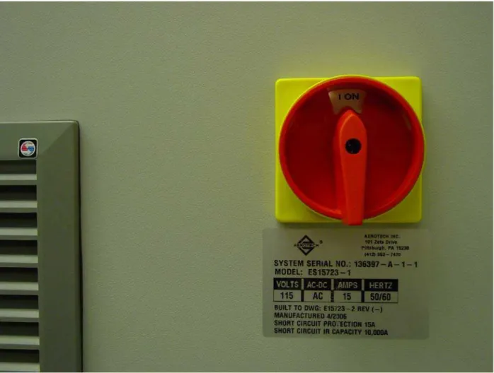
10 Main Power Supply Switch - ON ……… 11
11 Front Panel POWER ON Light ON - POWER ON ……… 12
12 Lower Panel Door Latch - OPEN ……… 13
13 Lower Panel Door - OPEN ……… 14
14 A3200 Npaq Green Switch Light - ON ……… 15
15 Front Panel RESET Light OFF - RESET ……… 16
16 Chassis Plans Panel Door - OPEN ……… 17
17 Chassis Plans Panel POWER - ON ……… 18
18 Chassis Plans Panel Door - CLOSE ……… 19
19 Log On to Windows - OK ……… 20
20 Automated Assembly of Microsystems - AREA CLEAR ……… 21
21 Log On to Windows - Shut Down... ……… 22
22 Front Panel POWER ON Light OFF - POWER OFF ……… 23
23 Main Power Supply Switch - OFF ……… 24
24 Lower Panel Door Latch - OPEN ……… 25
25 Lower Panel Door - OPEN ……… 26
26 APC Uninterruptible Power Supply - OFF ……… 27
27 Compressed Air for Festo Vacuum System - OFF ……… 28
28 Compressed Air for Aerotech Stages - OFF ……… 29
29 Compressed Air for Granite Table Base - OFF ……… 30
30 Breakout Blocks JM1BB and JM2BB Electrical Connection ……… 32
31 Festo Vacuum System ……… 37
32 Module JM2 ……… 38
33 Rear Panel - 1TB to 4TB ……… 39
34 Rear Panel - 2TB - DC 24V, 5A ……… 40 35 Rear Panel - 4TB - Breakout Blocks J9BB, J10BB, JM2BB & JM1BB
iv
PREFACE
Automated Assembly of Microsystems Project
The Automated Assembly of Microsystems Project at the National Research Council of Canada (NRC) started around June 2005. Team members include Shafee Ahamed, Vibhor Gupta, Dave Kingston, Ajit Pardasani, Alfred Sham (Left September 2006) and Brian Wong. Guest worker includes Pierre-Nicolas Porcin-Raux (August-December 2006).
For further assistance, please contact Mr. Ajit Pardasani, Project Leader, as follows:
Address: 800 Collip Circle, London ON N6G 4X8
Phone: (519) 430-7085
Email: [email protected]
Automated Assembly of Microsystems Start Up and Shut Down Procedures
To provide feedback on the content of this document, please contact Mr. Brian Wong as follows:
Address: 800 Collip Circle, London ON N6G 4X8
Phone: (519) 430-7083
Email: [email protected]
December 2006 (Version 2) June 2006 (Version 1)
IMPORTANT! PLEASE READ THIS FIRST
The Automated Assembly of Microsystems Start Up and Shut Down Procedures are still in theirs preliminary stage of development and are provided as is. Assumptions were made that users of the equipment have general knowledge on the computing, electrical, mechanical and software systems. Please follow the instructions with caution.
1.0 Introduction
The Automated Assembly of Microsystems Project makes use of a variety of precision devices such as stages and manipulator, with integrated compressed air, computer, vacuum and vision systems, etc. to assist the user in developing a generic platform for micro-assembly automation.
This document will guide the user through sets of figure-by-figure with step-by-step instructions to perform proper equipment start up and shut down procedures.
2
2.0 Start Up Procedure
Step 1:
Check that all cables, parts and tubing are securely fastened [Fig. 1]. Do the same for all the connecting devices in Appendix C.
Note: Due to the nature of this high precision equipment, the motion system will require calibration or tuning whenever a related part of the device has been modified or
relocated. And to minimize vibration, external stimuli should be avoided when the equipment is in operation.
Step 2:
Ensure the working area is clear for the motion system to be energized [Fig. 1].
Step 3:
Turn on the compressed air (Blue Lever) for the granite table base as shown in Figure 2. It might take some time for the pressures in the system to be stabilized.
4 Step 4:
Turn on the compressed air (Blue Lever) for the Aerotech stages as shown in Figure 3. It might take some time for the pressures in the system to be stabilized.
Step 5:
Turn on the compressed air (Green Lever) for the Festo vacuum system as shown in Figure 4. It might take some time for the pressures in the system to be stabilized. EMC Specifications
With reference and extracted from the Manual “FESTO Operating instructions for the Proportional pressure regulator type MPPES-...” “Make sure that high-frequency interference sources (e.g. walkie-talkies, hand telephones or other non-suppressed devices) are kept at a safe distance from the MPPES-...” “In this way you can avoid increased tolerances of the output pressure...”
6 Step 6:
Locate the black power cable (with the Hubbell Plug) coming out of the bottom left of the console as shown in Figure 5.
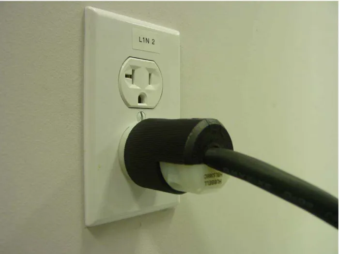
Step 7:
Insert the Hubbell Plug into one of the NEMA 5-20R sockets labelled “L1N 2” if needed for the 120V AC 20A Power Supply as shown in Figure 6.
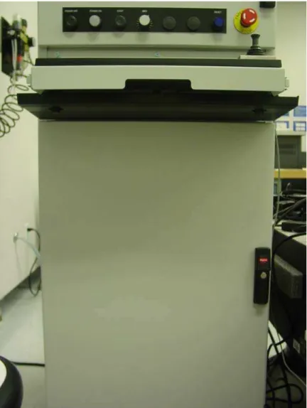
8 Step 8:
Turn the lower panel door latch clockwise as shown in Figure 7.
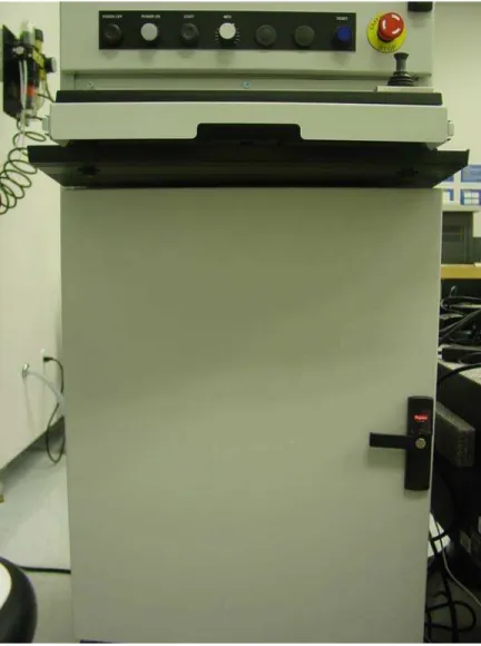
Step 9:
Open the lower panel door as shown in Figure 8.
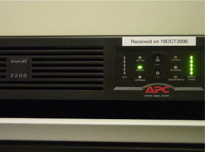
10 Step 10:
Press the (I) or (Test) button to switch on the APC Uninterruptible Power Supply as shown in Figure 9. According to APC, the battery charges to 90% capacity during the first four hours of normal operation. Close the lower panel door if needed.
Step 11:
Turn on the main power supply switch on the back of the controller computer cabinet as shown in Figure 10.
12 Step 12:
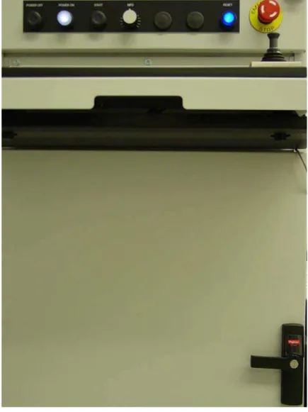
Press on the front panel POWER ON button and the POWER ON light should turn on as shown in Figure 11. The RESET light could be either on or off at this time.
Step 13:
Turn the lower panel door latch clockwise as shown in Figure 12.
14 Step 14:
Open the lower panel door as shown in Figure 13.
Step 15:
Check that both the A3200 Npaq Green Switch and the Green Switch light are ON [Fig. 14]. If this is not the case, put the switch in its ON position and the light should turn on as shown in Figure 14.
16 Step 16:
If the front panel RESET light is still on, press the RESET button to have it turned off as shown in Figure 15.
Step 17:
Open the Chassis Plans panel door as shown in Figure 16.
18 Step 18:
Press on the Chassis Plans panel POWER button to turn on the controller computer as shown in Figure 17. It might take some time for the controller computer to be booted up.
Step 19:
Close the Chassis Plans panel door as shown in Figure 18 if there is no immediate need for the other devices on the controller computer.
20 Step 20:
Once the controller computer is booted up, choose “OK” to start using the controller software as shown in Figure 19.
3.0 Shut Down Procedure
Step 1:
Check that all cables, parts and tubing are securely fastened [Fig. 20, 31 & 32]. Step 2:
Ensure the working area is clear for the motion system to be de-energized [Fig. 20].
22 Step 3:
Choose “Shut Down...” to shut down the controller computer as shown in Figure 21. It might take some time for the computer to be shut down. Please ensure this step is finished before going to the next step.
Step 4:
Press on the front panel POWER OFF button and the POWER ON light should turn off as shown in Figure 22.
24 Step 5:
Turn off the main power supply switch on the back of the controller computer cabinet as shown in Figure 23.
Step 6:
Turn the lower panel door latch clockwise as shown in Figure 24.
26 Step 7:
Open the lower panel door as shown in Figure 25.
Step 8:
Press the (O) button to switch off the APC Uninterruptible Power Supply as shown in Figure 26. Close the lower panel door and remove the Hubbell Plug from one of the NEMA 5-20R sockets labelled “L1N 2” [Fig. 6] if needed.
Note: For as long as the Hubbell Plug is inserted into one of the NEMA 5-20R sockets labelled “L1N 2”, there is power (120V AC 20A) supply to the APC Uninterruptible Power Supply Unit (Smart-UPS 2200).
28 Step 9:
Turn off the compressed air (Green Lever) for the Festo vacuum system as shown in Figure 27. It might take some time for the compressed air to be exhausted.
Step 10:
Turn off the compressed air (Blue Lever) for the Aerotech stages as shown in Figure 28. It might take some time for the compressed air to be exhausted.
30 Step 11:
Turn off the compressed air (Blue Lever) for the granite table base as shown in Figure 29. It might take some time for the compressed air to be exhausted and this is the last step of the shut down procedure.
Appendix A Electrical Connection
32
A.1 Breakout Blocks JM1BB and JM2BB Electrical Connection
Please refer to 4/03/06 AEROTECH, INC. Filename 136397 E15723-207.DWG for Breakout Blocks J9BB and J10BB Existing Electrical Connection.
DC 24V, 5A + - J9BB 13 ⊥ 12 25 11 24 10 23 9 22 8 21 7 20 6 19 5 18 4 17 3 16 2 15 1 14 J10BB 8 ⊥ 7 15 6 14 5 13 4 12 3 11 2 10 1 9 JM2BB 8 ⊥ 7 15 6 14 5 13 4 12 3 11 2 10 1 9 JM1BB 13 ⊥ 12 25 11 24 10 23 9 22 8 21 7 20 6 19 5 18 4 17 3 16 2 15 1 14
Figure 30. Breakout Blocks JM1BB and JM2BB Electrical Connection
1K 1K 1K
Appendix B
34
B.1 Breakout Block JM1BB Assignment
Table 1. Breakout Block JM1BB Assignment (for Module JM1) Label Description Part No. Pin Cable
Colours
Cable Description
1 2 Black Switch Output
(On = 24 V DC) (Off = 0 V DC) 0 V (for Switch Output Pin 1 Setting) 2 1 Black 0 V (for Switch Output Pin 2 Setting) Switch Output (On = 24 V DC) (Off = 0 V DC) 3
FESTO On-off Valve HEE, D Series (HEE-D-MINI-24) w/ FESTO Plug Socket with Cable KMEB (KMEB-1-24-5-LED)
172956 w/ 151689
⊥ Green/Yellow Ground
4 1 Brown + 24 V DC Supply Voltage
5 2 White Output B 6 3 Blue 0 V 7 FESTO Pressure/Vacuum Sensor (SDE1-D10-G2-R18-C-P2-M8) w/ FESTO Plug Socket with Cable SIM (SIM-M8-4GD-5-PU)
192027 w/ 158961
4 Black Output A
8 2 Brown Ground (of Win)
9 3 Green Ground (of 24 V DC)
10 4 Yellow Win (Setpoint Value Input, 0-10 V
DC)
11 6 Pink Xout (Actual Value Output)
12 7 Red 24 V DC (Supply Voltage)
13
FESTO Proportional Pressure Regulator MPPES (MPPES-3-1/8-6-010) w/ FESTO Plug Socket with Cable KMPPE (KMPPE-B-5)
187352 w/ 161878
8 Blue Ground (of Xout)
14 1 Brown +
15 3 Blue -
16
FESTO Vacuum
Generator (VADMI-70) w/ FESTO Plug Socket with Cable KMYZ-2 (KMYZ-2-24-M8-0.5-LED) & FESTO Plug Socket with Cable SIM (SIM-M8-3GD-5-PU) 162507 w/ 177676 & 159421
4 Black Switch Output (Vacuum Generation) 17 1 Brown + 18 3 Blue - 19 FESTO Vacuum Generator (VADMI-70) w/ FESTO Plug Socket with Cable KMYZ-2 (KMYZ-2-24-M8-0.5-LED) & FESTO Plug Socket with Cable SIM (SIM-M8-3GD-5-PU) 162507 w/ 177676 & 159421
4 Black Switch Output (Release Pulse)
20 21 22 23 24 25 ⊥
B.2 Breakout Block JM2BB Assignment
Table 2. Breakout Block JM2BB Assignment (for Module JM2) Label Description Part No. Pin Cable
Colours Cable Description 1 2 3 4 5 6 7 8 9 10
Not Connected N/A N/A
11 N/A Brown 12-24 V DC (Supply Voltage)
12 N/A Blue 0 V (Ground)
13 N/A Grey Analog Output (1-5 V)
14 N/A Black OUT1
15
FESTO Miniature Flow Sensor SFEV-R Series (SFEV-R1000-L-2PD-K1) w/ FESTO Miniature Flow Sensor SFET-R Series (SFET-R1000-L-WQ4-D-K3)
538555 w/ 538539
N/A White OUT2 ⊥ FESTO Proportional Pressure Regulator MPPES (MPPES-3-1/8-6-010) 187352 ⊥∗ Dark Green (User Defined) Earth (Ground)
36
Appendix C
C.1 Festo Vacuum System
38
C.2 Module JM2
The Module JM2 [Fig. 32] is part of the Festo Vacuum System [Fig. 31].
C.3 Rear Panel - 1TB to 4TB
The rear panel is accessible through the rear panel door of the controller computer cabinet. Please refer to 4/03/06 AEROTECH, INC. Filename 136397 E15723-204.DWG for the original rear panel assembly details.
40
C.4 Rear Panel - 2TB - DC 24V, 5A
C.5 Rear Panel - 4TB - Breakout Blocks J9BB, J10BB, JM2BB & JM1BB and Module JM1
Figure 35. Rear Panel - 4TB - Breakout Blocks J9BB, J10BB, JM2BB & JM1BB and Module JM1