7
thInternational Conference on
Computer and IT Applications in the Maritime Industries
COMPIT’08
Liège, 21-23 April 2008
Edited by Volker Bertram, Philippe Rigo
This work relates to Department of the Navy Grant N00014-08-1-1007 issued by Office of Naval Research Global. The United States Government has a royalty-free license throughout the world in all copyrightable material contained herein.
ISBN-10 2-9600785-0-0 ISBN-13 978-2-9600785-0-3
Sponsored by www.onrglobal.navy.mil www.GL-group.com www.aveva.com www.sener.com www.bureau-veritas.com http://dn-t.be www.exmar.be www.numeca.be www.grc-ltd.co.uk
Platform for European Research Projects ADOPT http://adopt.rtdproject.net
CAS http://www.shiphullmonitoring.eu
Index
François-Xavier Dumez, Cedric Cheylan, Sébastien Boiteau, Cyrille Kammerer, 6 Emmanuel Mogicato, Thierry Dupau, Volker Bertram
A Tool for Rapid Ship Hull Modelling and Mesh Generation
Jan Tellkamp, Heinz Günther, Apostolos Papanikolaou, Stefan Krüger, Karl-Christian Ehrke, 19 John Koch Nielsen
ADOPT - Advanced Decision Support System for Ship Design, Operation and Training - An Overview Steven J. Deere, Edwin R. Galea, Peter J. Lawrence 33 Assessing the Suitability of Ship Design for Human Factors Issues Associated with Evacuation and Normal Operations
Jean-David Caprace, Frederic Bair, Nicolas Losseau, Renaud Warnotte, Philippe Rigo 48 OptiView − A Powerful and Flexible Decision Tool Optimising Space Allocation in Shipyard Workshops Vidar Vindøy 60 A Functionally Oriented Vessel Data Model Used as Basis for Classification
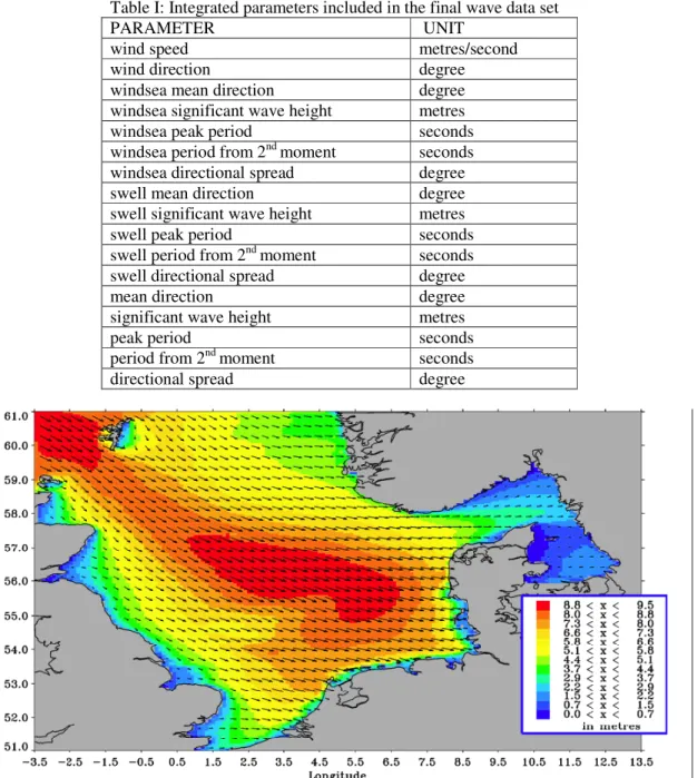
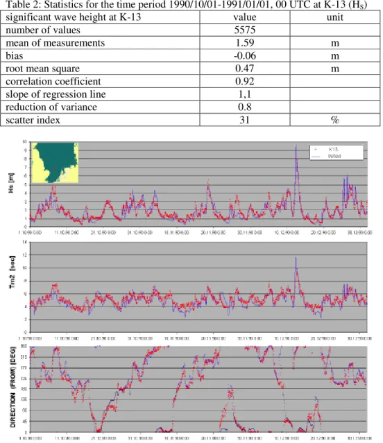
Heinz Günther, Ina Tränkmann, Florian Kluwe 70
ADOPT DSS - Ocean Environment Modelling for Use in Decision Making Support
Rowan Van Schaeren, Wout Dullaert, Birger Raa 81 Enriching the Berth Allocation Problem
Philippe Rigo, Djani Dundara, Jean-Louis Guillaume-Combecave, Andrzej Karczewicz, Alan Klanac, 92 Frank Roland, Osman Turan, Vedran Zanic, Amirouche Amrane, Adrian Constantinescu
IMPROVE - Design of Improved and Competitive Products using an Integrated Decision Support System for Ship Production and Operation
Catalin Toderan, J-L Guillaume-Combecave, Michel Boukaert, André Hage, Olivier Cartier, 107 Jean-David Caprace, Amirouche Amrane, Adrian Constantinescu, Eugen Pircalabu, Philippe Rigo
Structural Optimization of a 220 000 m³ LNG Carrier
Fernando Alonso, Carlos González, Antonio Pinto, Fernando Zurdo 121 Integrated Management of Ship Compartments
Antti Metsä, Pekka Ruponen, Christopher Ridgewell, Pasi Mustonen 135 Flooding Simulation as a Practical Design Tool
Charles Forrest 148
Development of an Innovative Surface Design Tool
Sandra Schrödter, Thomas Gosch 163
SESIS – Ship Design and Simulation System
Wilfried Abels, Lars Greitsch 174
Using a Bridge Simulator during the Early Design-Stage to Evaluate Manoeuvrability
Thomas Glotzbach, Matthias Schneider, Peter Otto 185
Multi System Mission Control for Teams of Unmanned Marine Vehicles – Software Structure for Online Replanning of Mission Plans
Marcus Bentin, Folgert Smidt, Steffen Parth 200
Robert Hekkenberg 214 Development of a Rapid Conceptual Design Method for Inland Ships
Christian Cabos, David Jaramillo, Gundula Stadie-Frohbös, Philippe Renard, Manuel Ventura, 222 Bertrand Dumas
Condition Assessment Scheme for Ship Hull Maintenance
Thomas Brathaug, Jon Olav Holan, Stein Ove Erikstad 244
Representing Design Knowledge in Configuration-Based Conceptual Ship Design
Stefan Krüger, Florian Kluwe, Hendrik Vorhölter 260
Decision Support for Large Amplitude Roll Motions based on Nonlinear Time Domain Simulations
Andi Asmara, Ubald Nienhuis 271
Optimum Routing of Piping in Real Ships under Real Constraints
Matthias Grau, Carsten Zerbst, Markus Sachers 282
Building the Business Process View into Shipbuilding Data Exchange
Tomi Holmberg 291
Comprehensive Structural Design Package for Bulk Carriers
Carlos Vinícius Malheiros Santos 302
Production Simulation Applied to Military Shipbuilding
Rachel F. Nicholls-Lee, Stephen R. Turnock, Stephen W. Boyd 314 Simulation Based Optimisation of Marine Current Turbine Blades
Takakazu Nakamori, Mitsuru Kitamura, Kunihiro Hamada 329 Optimization of Arrangement of Longitudinal Stiffeners on Shell Plate at Fore and Aft Parts
of Ships
Dirk Wittkuhn, Karl-Christian Ehrke, John Koch Nielsen 338 ADOPT: Man-Machine Interface and Training
Björn Weidemann, Ralf Bohnenberg, Martin-Christoph Wanner 350 Shipyard Investment Planning by Use of Modern Process-Simulation and Layout-Planning Tools
Rafael Doig, Patrick Kaeding 364
Multi-Body Simulation of a Loading Operation
Karl Gunnar Aarsæther, Torgeir Moan 372
Autonomous Traffic Model for Ship Maneuvering Simulations Based on Historical Data
Andrea Caiti, Giuseppe Casalino, Alessio Turetta, Riccardo Viviani 384 Distributed Dynamic Programming for Adaptive On-line Planning of AUVs Team Missions with
Communication Constraints
Patrick Queutey, Michel Visonneau, Ganbo Deng, Alban Leroyer, Emmanuel Guilmineau, 392 Aji Purwanto
Computations for a US Navy Frigate Advancing in Head Waves in Fixed and Free Conditions
David Andrews, Lorenzo Casarosa, Richard Pawling 407
Interactive Computer Graphics and Simulation in Preliminary Ship Design
Hao Cui, Aykut Ölcer, Osman Turan 422
An Improved Particle Swarm Optimisation (PSO) Approach in a Multi Criteria Decision Making Environment
Djani Dundara, Dario Bocchetti, Obrad Kuzmanovic, Vedran Zanic, Jerolim Andric, Pero Prebeg 435 Development of a New Innovative Concept of Ropax Ship
Darko Frank, Alan Klanac, Svemir Bralic 450
A Concept for Concurrent Group Design of Ships
Yves Le Thérisien, Chantal Maïs 460
Virtual Reality – Tool of Assistance to the Design of the Warship’s Complex Systems
Thomas Haberkorn, Monique Chyba, Ryan Smith, Song. K. Choi, Giacomo Marani, Chris McLeod 467 Efficient Control of an Autonomous Underwater Vehicle while Accounting for Thruster Failure
Cassiano M. de Souza, Rafael Tostes 481
Shipbuilding Interim Product Identification and Classification System Based on Intelligent Analysis Tools
Jeroen F.J. Pruyn, Ubald Nienhuis, Eddy van de Voorde, Hilde Meersman 495 Towards a Consistent and Dynamic Simulation of Company Behaviour in the Maritime Sector
Adam Sobey, James Blake, Ajit Shenoi 502
Optimization of Composite Boat Hull Structures
Marc Wilken, Christian Cabos, Wiegand Grafe 516
Using CAD Data for Computation and Assessment of Global Ship Structures
Audun Grimstad, Arnulf Hagen 524
Customised Ship Design = Customised Ship Design Environments
Alan Klanac, Jasmin Jelovica, Matias Niemeläinen, Stanislaw Domagallo, Heikki Remes, 537 Structural Omni-Optimization of a Tanker
Hamid Hefazi, Adeline Schmitz, Igor Mizine, Geoffrey Boals 551 Multi-Disciplinary Synthesis Design and Optimization for Multi-Hull Ships
Dimitris Spanos, Apostolos Papanikolaou, George Papatzanakis, Jan Tellkamp 566 On Board Assessment of Seakeeping for Risk-Based Decision Support to the Master
Shimpei Watanabe, Kazuhiko Hasegawa, Philippe Rigo 578
Inland Waterway Traffic Simulator
Liming W. Salvino, Thomas F. Brady 589
Hull Monitoring System Development using a Hierarchical Framework for Data and Information Management
Yvonne R. Masakowski 603
Cognition-Centric Systems Design: A Paradigm Shift in System Design
Index of authors 608
Call for Papers COMPIT’09
A Tool for Rapid Ship Hull Modelling and Mesh Generation
François-Xavier Dumez, GRANITX, Brest/France, [email protected] Cedric Cheylan, Sébastien Boiteau, Cyrille Kammerer, DCNS, Lorient/FranceEmmanuel Mogicato, Thierry Dupau, BEC, Val de Reuil/France Volker Bertram, ENSIETA, Brest/France
Abstract
The paper describes SILEX, a tool for the rapid and associative generation of numerical hull models linked to different simulation tools. The underlying concepts are described. Industry applications illustrate the capabilities and efficiency of the approach.
1. Introduction
From the early phases of development, modern ship design methods use CAD models built of several tens of thousands of elements. Therefore 3D CAD tools used in other industrial fields (aircraft, cars…) are unsuitable for our purposes in view of the required rapid design cycles. Our industry needs an integrated design cycle associating the different fields of expertise around a common product model that “communicates” with different software packages (hydrodynamic, structure, stability, class rules, signatures, etc.).
Financed by DCNS and the French ship model basin BEC (Bassin d’Essais de Carènes), GRANITX has developed an ultra fast 3D ship modelling and grid generation tool based on four cornerstones: parametric modeller, generativity, granularity, and propagation. These four elements enable the creation of 3D CAD models of complete ships in a few days. The model obtained is topologically connected, allowing automatic updates of the definition by changing some parameters, and to readily extract a structural mesh of the whole ship or its associated compartment plans.
2. Modelling concepts
SILEX is based on object modelling through the implementation of a parametric modeller, generative systems, granularity, and propagation. The incorporation of these objects and the interaction of their construction modes allow the creation of systems as well as more sophisticated object creation processes. The resulting global model has a complex architecture which enables an associative and fluid updating of the design when global parameters or local elements are modified.
2.1. Parametric modeller
Like most commercial CAD tools, SILEX employs a parametric modeller. In this model, all operations which generate points, curves, surfaces, or volumes are objects which have other objects and/or numerical values as parameters. The global geometry is the result of a construction based on these parameters or specifications. Thus, a point in space is a geometrical construction based on the 3 coordinates (X, Y, Z), or the intersection between two curves on a surface, or the intersection of a curve and a surface in space.
The simplest example is the construction of a segment or a line from two points, Fig.1. Following the logic of parametric description, the line and the two points exist in the model independently of their respective geometrical construction which is only the result of a construction based on their own respective parameters. When the value of Y1 is modified, the geometrical representation of the point Pnt 1 is updated, and Pnt 1 sends an event message to all objects of the model in order to inform them that its geometry has been modified. Line 3 which receives this information can then reconstruct itself.
This approach has an obvious benefit in the case of a ship CAD model in the iterative phase of the design. Take for example a 2D cross section of the ship, Fig.2. Here, the decks are automatically limited by the hull surface. The section is a parametric object which incorporates 2D objects (points, lines, etc.) and which lies in a plane. The plane is constructed from a single point and a direction. The point here lies on a curve (here the X axis) at a given curvilinear abscissa from the reference point (the origin in this case). A modification of the value of the curvilinear abscissa will lead to a cascade of associative updates of all the elements of the project. The “Section” object used in this example is a complex object constructed of geometrical objects (points, lines) or geometrical analysis (curve/curve intersections for example).
Fig.1: Parametric model Fig.2: Before (top) and after (bottom) modi- fication
2.2. Generative systems
The use of generative systems in SILEX is an innovative concept compared to traditional CAD systems. It enables the creation of a set of identical objects but positioned according to project specific topological rules with respect to other existing objects in the model. The generative treatment is performed by “system” objects which are dedicated to creating a certain type of object. One can then derive different “system” objects for points, planes, intersections, etc. The “system” objects are themselves associative. This characteristic is particularly well suited to ship design applications where tens of thousands of identical base elements have to be created (bulkheads, decks, plates, primary and secondary stiffeners) but different position, orientation, and parameters (size).
Fig.3 shows a simple example of a point which lies on a spline curve. The system has for parameters, the curve, a reference point and a number of points (or the spacing between points). The resulting construction of these parameters is a set of points which are of the type “point on curve”. The points are incorporated in a system which does not possess an actual geometry. Each point of the system is constructed and initialised by the system. One can then build a system of planes whose only parameter is the system of points. The plane system builds a set of planes. Each plane of the system is defined rests on one of the points of the point system and the supporting curve. If one modifies the specifications of a system (e.g. the number of points on the curve) the system will create the corresponding objects, see Fig.4 where the number of points is increased from 10 to 23. In this case, the plane system receives a request to update the point system and will also reconstruct itself by creating or suppressing the corresponding planes.
If one modifies the supporting curve of the point system, Fig.5, the points will recursively update the parameters and reconstruct their geometry in order to position themselves on the new supporting curve. Each of the planes will, along the same principle of automatic updating of the geometry, reconstruct its respective geometry.
A system may have several other systems as parameters. The beam system, for example, uses two distinct point systems and a supporting surface. This system constructs a set of beams which rest at their extremities on the points and computes a mean plane which intersects the supporting surface, Fig.6.
Fig.5: Change in supporting curve Fig.6: Beam system 2.3 Granularity
The generative process is relevant only if the objects created can be accessed individually in order to modify them locally, or to change their specifications. This function is performed through granularity. Hence, through granularity, each object created by a system is thereafter totally autonomous, and the system can subsequently “forget” the objects it has created. For the user, it is therefore seen as if it had been constructed as an independent unit. It can therefore be modified or destroyed. The object is doubly associative: through the system which created it, and through its own specifications. Hence, granularity enables the best use of the “batch” creation process, while maintaining the possibility to adapt the geometry of a particular object to a specific local configuration.
To illustrate this concept, the two examples shown in Fig.3 and Fig.6 are further developed. In the first case, the points of the point system have been modified point by point by changing their respective curvilinear abscissa, Fig.7. The corresponding planes update their own geometry automatically. In the second case, the supporting point system has been modified, some of the beams have been deleted, and some of the beams’ end points have moved, Fig.8. These examples of elementary processes illustrate the complementarities of the concepts of generic creation and elementary granularity which are implemented in the model. The principle is identical to the one found in multi-agent simulation models where multiple autonomous agents are created, each
programmed with a specific individual behaviour. These agents interacting with each other enable the dynamic modelling of complex processes.
Fig.7: Change in points Fig.8: Modification of beam system 2.4 Propagation
A ship offers a natural direction, the longitudinal axis, along which the changes in topology are minimal. This axis is used to minimize the 3D design process which is inherently the most time consuming. Simple procedures such as compartmenting and superstructure design are long and tedious to perform in 3D and the result is difficult to alter if the project has to be modified. This difficulty in describing objects such as compartments is even more acute for structural elements (numbers, characteristics, size and position).
Still, good design practice imposes continuity in compartments and structure in the longitudinal direction and across the decks of the ship. This continuity is perturbed by integration constraints, longitudinal optimization of the beam strength, or regulatory criteria (structure, stability, etc.). However, these longitudinal evolutions are gradual and coherent, so that a privileged longitudinal axis can still be exploited in the construction of a CAD model.
Following the traditional ship design convention, SILEX defines the concept of ship sections in which the compartments and the structural scantlings are uniform and regular. Each section is defined by a 2D plan. The ship is thus built of different sections described by a series of plans which allow the modelling of longitudinal discontinuities. The initial plan, Fig.9, corresponds to the mid-ship section of a ship. This initial geometry is then propagated to the plans of the upstream and downstream sections (forward and aft), Fig.10.
Fig.9: Mid-ship section Fig.10: Propagation of plans
The plans thus generated inherit the attributes of their predecessors (based on continuity) while they can subsequently be modified locally in order to be further propagated to their successors. This
propagation is associative and, like other systems, the objects propagated from section to section are autonomous (principle of granularity). One can modify the position of existing elements, or add and subtract different elements towards the stern or the bow of the ship, Fig.11. An object thus propagated through a plan can hence be associative in three ways: through its own specifications, through the system which created it, and through the plan which propagated it. The coexistence of multiple layers of parametric representation is one of the original characteristics of SILEX which enables a rapid modelling of the ship structure while automatically updating the definition during the iterative design process.
Fig.11: Example of evolutions in the sections 2.5 The block
Building on the concepts of parametric modeller, generative, granular systems, and propagation, a process can now be developed to generate a 3D numerical model which requires minimal designer intervention and hence provides a fast grid generation solution. The construction of the 3D model uses the concept of rings or blocks. Propagation ensures a direct link between adjoining sections. From these 2D elements, longitudinal elements may be constructed. E.g. a deck line described in a 2D section S1 and propagated in section S2 will be used as a parameter to build the corresponding deck or longitudinal bulkhead elements, Fig.12.
The block is a system-type object because it generates from given parameters (forward and aft sections) a set of flat panels and longitudinal panel joints. As in any system object, the objects automatically generated may subsequently be modified locally or even eliminated. The block is programmed to automatically create sub-section systems which, like the section system, are in turn propagation mechanisms, Fig.13.
Each sub-section automatically maintains the intersections with all longitudinal objects and guarantees the upstream/downstream links between the intersections of a single longitudinal object with its two intersecting sub-sections. This technology creates a propagation mechanism within a block just as it is done with the sections. The section system of a block rests on a master sub-section. All objects created in this sub-section will be propagated downstream to the next sub-sub-section. The traces of the intersection elements in each sub-section allow the direct construction of transverse stiffeners or transverse panel elements like frames, Fig.14.
Fig.12: Longitudinal elements in a block
Fig.14: Creation of transverse elements 2.6 Stiffeners
Longitudinal stiffeners are modelled by 2D point systems in the sections and by beam systems in 3D. This choice is appropriate since flat panels are typically stiffened at a regular spacing. Similarly to the definition of bulkheads and decks in 2D, where lines and more generally curves are used, point systems will be used to define the longitudinal stiffeners while associating them with the attributes of stiffener types and section characteristics.
Fig.15: Longitudinal stiffeners
The 2D point systems in the sections are used as parameters to create 3D longitudinal beam systems in the blocks, each of the beams of the system being supported by panels, Fig.15. This generation is performed automatically similarly to all the elements of a longitudinal block. Using the beam system parameters, a stiffener can be deleted, or its end points can be modified, or the upstream or downstream points can be moved in order to adapt the structure to the problem at hand.
Transversally, beam systems are created to stiffen the longitudinal panels using the point systems which belong to the longitudinal stiffeners, Fig.16. The transverse panels, the transverse point systems, and the beam systems are naturally propagated from an upstream section to a downstream section.
Fig.16: Transverse stiffeners
In the sub-sections of a block, the intersections between the longitudinal stiffeners and the sub-section can easily be found. Transverse panels (web frames, bulkheads…) can thus be created and stiffened by new beam systems which are supported explicitly by the longitudinal stiffeners, Fig.17. As for all objects created by propagation, each object generated is linked to its parent upstream and inherits its parameters. This principle is applicable to a system object such as beam systems, but also to each beam object of the system. Hence, a whole system can be modified causing this global information (number of beams, pitch, attributes…) to be propagated downstream or a single beam (principle of granularity) may be modified and similarly, this isolated change will also be propagated downstream.
3. Modelling applications
SILEX Structure was primarily developed to provide CAD models of the structure of ships in a very short time while automatically updating its definition throughout the design iterations of the project. Some applications are briefly described below.
3.1 Grid generation
The efficient structural modelling relies on a topological definition where the different surfaces defining the panels are naturally connected. Also, the stiffener end points are located on curves which are the intersections between supporting panels. The panels or plates are defined based on a closed contour built with curve elements of the model. Hence, stiffeners are supported by point systems which lie on panel contour curves. More generally, all the elements of a SILEX model are connected to neighbouring elements. The connexions are often implicit because a large part of the transverse and longitudinal elements are automatically created.
The grid generation algorithm transforms panels in shell elements, and stiffeners in beam elements based on a classical grid generation process (points → curves → surfaces) in order to automatically obtain a complete mesh of the ship structure by simply adjusting the mean grid size to meet the modelling requirement.
The resulting meshes may then be exported to standard formats used by common commercial solvers (Abaqus, IDeas, Femap). For example, the mesh of a frigate which was created in three working days and exported to the Abaqus format. In another example, a tanker section was modelled and meshed using SILEX Structure in two working days and exported in the Femap format.
3.2 Structural analysis
SILEX has a function to extract from the 3D model a series of ship sections with its associated scantling information suitable for analysis by the MARS software of Bureau Veritas (BV). Inversely SILEX can construct 2D sections by uploading MARS sections which have been developed according to BV rules. These functions enable quick data exchange with associated gains in time and reduced risk of errors. They also significantly accelerate the process of checking the structure for compliance with BV (and potentially other) rules or constructing a ship structure compliant with the rules.
Fig.18: 180 compartments on a cruise vessel Fig.19: 3D model of the Atalante 3.3 Compartment identification
As that all decks and bulkheads are connected, it is possible to automatically extract the ship compartments, Fig.18. Instantaneously, all the compartments of the ship can be identified with their volume and centre of volume. This information may then be used, for example, for intact and
damaged stability calculations, or to compute the static loading when the nature, the density, and the volume of the content of each compartment is known.
3.4 Weight budget and bill of materials
The available description of the panels and stiffeners which constitute the structural model, allows estimating the structural weight of the ship. This information is vital at the early design stage and is available from the 3D numerical model with great accuracy. The model can also be analysed to obtain a bill of materials: quantity of plates by thickness and grade, length of stiffeners by type of section, etc… Further extensions can easily be imagined in areas of cost estimation with the computation of the length of welds and complexity of plate shapes.
3.5 General arrangement
General arrangement considerations are not directly addressed by SILEX but can be treated by specific codes which have a large choice of functions available to describe the arrangement details. One such example is the Atalante model developed for IFREMER in cooperation with the TLB naval architect office for the mid-life refurbishment of this vessel, Fig.19. The whole structure was modelled using SILEX structure, and then exported in STEP format to Rhino3D where the deck machinery and the internal arrangements were added.
3.6 HCM export
A special interface was developed for Bureau Veritas for the export of structure models in the HCM format of the Condition Assessment Scheme (CAS) consortium. This interface allows exporting structural models in part or in total, as in the example shown in Fig.20. The export allows identifying welding seams to automate recognition of related actual plates.
Fig.20: Tanker cargo hold 4. Industrial applications
4.1 ‘Charles de Gaulle’ aircraft carrier
Aircraft carriers certainly have highly complex topologies because of the size of the ship and the numerous unique features (sponsons, elevators, islands, hangar) which induce specific structural issues. For these reasons, BEC employed SILEX to create a finite element model of the ‘Charles de Gaulle’. The size and the structural complexity of this ship could only be tackled by the development of macro-type sub-routines. These automatically created blocks of ships, Fig.21, starting with set of data contained in “text” files very easy to input. The blocks generated were then assembled and
adjusted to constitute the whole ship. This strategy is best suited to near cylindrical topologies. For other elements, e.g. the oblique runway, the model had to be created by the man-machine interface.
Fig.21: Block of the ‘Charles de Gaulle’ with zoom on mesh
The longitudinal structure of the ship has a pseudo-cylindrical topology which follows the evolution of the hull form. For a given ship block, the transverse section of the ship shows few geometrical variations. For example, a deck may have a slight inclination with the horizontal plane, or a longitudinal bulkhead may have an angle with the ship’s axis. This feature allows defining for each transverse section a grid which is supported by the main longitudinal structural members of the ship, Fig.22. These structures are (1) hull and decks, (2) longitudinal bulkheads, and (3) longitudinal girders. The propagation or “extrusion” process of the mesh enables the creation of the longitudinal structure of the ship. Each line of this mesh corresponds to a stiffened plate. This strategy is naturally integrated in the modelling process of SILEX, Fig.23.
The scantlings of the longitudinal structure of a ship are generally constant in a block to simplify the construction process and the management of the steel plates. This characteristic allows the ship to be divided in a number of blocks in which the scantlings are uniform. Hence, for each block and each supporting line of the section grid, the following information is specified: plate thickness, main longitudinal stiffener sections, secondary longitudinal stiffener sections, frames sections, number and spacing of the longitudinal stiffeners, and end conditions for the longitudinal stiffeners.
Fig.22: Section Fig.23: Middle part of the ship
SILEX automatically intersects each block with transverse planes positioned on the construction frames of the ship. These frames correspond to either a watertight bulkhead (generally the end section of a block), or a stiffened frame defining the sub-section of a block. The transverse structure is
consistent with the previous section grid, Fig.22, and more specifically it lies on a series of lines which form a closed contour which corresponds either to a stiffened transverse frame (beam), or a stiffened transverse plate (the plate is the surface within this contour).
The data input concerns on one hand the main section at the beginning of the block and on the other all the sub-sections of the block. The transverse scantlings of each sub-section of a block are considered uniform between two adjacent sub-sections while possibly being different from the transverse scantlings of the main section of the block. For example, the main longitudinal stiffeners intersect all the sub-sections of a block (the construction frames of the ship). For each closed contour, one prescribes number of sides of the contour, transverse plate thickness, section of main vertical stiffeners, section of secondary vertical stiffeners, section of horizontal stiffeners, end conditions for the vertical and horizontal stiffeners. This data is input for the section at the beginning of the block and for the sub-sections of the block.
The topological and scantling data contained in the structural drawings of the ship are input in Excel files. In this particular case, the model represents 70 m of the ship and is made of 17 blocks. The grid is composed of 580 supporting lines which delimit 252 closed contours. Only 30% of the lines and contours have been attributed some information; the others only serve as continuity in the programming algorithms. The man-machine interface for SILEX to input the data is replaced by a script of macro-commands which makes use of all the strategies and functions developed in SILEX. The different steps of the script were as follows:
- Reading the topological and scantling data
- Creation of the axis system, of points, planes, and sections which enable the positioning of the main frame on the axis of the ship,
- Creation of the supporting points for the plates of each section,
- Creation of the plates from the points and of the longitudinal stiffeners in each section, - Creation of the transverse plates and stiffeners,
- Creation of blocks by joining two adjacent sections, - Creation of the transverse stiffeners of the section,
- Creation of the transverse plates and stiffeners of the sub-section, - Mesh generation for the blocks and sections.
The different blocks and parts of ships generated are assembled and adjusted using Femap or IDeas to build the complete ship. If two adjacent parts of ships have significant topological differences (e.g. a deck or a longitudinal bulkhead disappearing) manual adjustments of either adjacent block at their interface are required to achieve an accurate description of the structure.
The intensive use of macro-commands reduced the workload related to data input drastically. Although this vessel does not fulfil the fundamental assumption of longitudinal continuity, SILEX allowed creating the complete mesh of the ship within 4 man-months. A frigate or a commercial vessel with regular topology would take typically one man-month.
4.2 DCNS Frigate
The first designs at DCNS modelled with SILEX were frigates described using entirely the man-machine interface. The description process was coherent with the way ship structures are usually designed: The hull form was imported and the bulkheads were allocated. The mid-ship section was described as a 2D plan with lines representing the main plates (decks, hull, longitudinal bulkheads, and girders) and with the properties of the longitudinal stiffeners attached to the panels. Then the transverse elements in the 2D sketch of the mid-ship section were described: transverse bulkheads, frames, and main vertical stiffeners. The mid-ship section was propagated to the other sections of the ship, and geometry and scantlings adapted at each section. Then the blocks between adjacent sections were generated, longitudinal stiffeners locally adapted, and transverse elements (frames, web frames,
and beams) described. The next step was the manual description of zones where propagation was not possible (bow and odd shapes in the superstructure), Fig.24. Then the weight budget was generated and the bill of materials listed. For a simplified preliminary project model, all these tasks can be performed in less than one man-week for a whole frigate.
The strong associativity of the elements comes into full power with the frequent design changes in early design (hull shape, bulkhead positions, scantlings following structural analysis, geometry like spacing between decks or superstructures, sometimes even length and beam). Here SILEX allowed model updates in extremely short time with just a few operations and thus evaluation of their impact on the ship’s characteristics and performance, notably weight and centre of gravity.
Fig.24: Bow block Fig.25: Principal stresses in frigate under wave loading
SILEX generated a finite-element model adapted to global analysis of the ship strength. The behaviour of this model to static wave loading allows identifying early in the design not only the zones presenting a risk in terms of structural integrity, but also potential areas of weight savings. The computation takes into account a response of the ship in a static sinusoidal wave, Fig.25. Several configurations can be considered with respect to wave position or direction.
The whole ship was modelled with all panels modelled as “shell” element and the primary and secondary stiffeners modelled as “beam” elements. The materials were assumed elastic in behaviour. Gravity and buoyancy forces (as hydrostatic pressure field) were applied. Thermal loading resulting from exposure to the sun of parts or the whole of the ship could have been added, but was not considered in this case. For each required configuration including still water and wave loadings the results are pressure field on the hull, stresses (Von Mises, longitudinal, maximum principal). Exporting a file with the displacements of all node points allows access to the ship deflection. The applied loads can also be integrated to provide the resulting shear forces and bending moments applied to the ship.
5. Conclusion
SILEX has been developed as an integration tool to prepare models for sophisticated simulation tools, making the ship design process more efficient. As demonstrated by applications shown, SILEX answers industry demands with a product adapted already to core problems (topology, structure, weights). Further improvements are to come from the continued partnership with DCNS and BEC.
ADOPT – Advanced Decision Support System for Ship Design, Operation
and Training – An Overview
Jan Tellkamp, FSG, Flensburg/Germany, [email protected] Heinz G ¨unther, GKSS, Geesthacht/Germany, [email protected] Apostolos Papanikolaou, NTUA, Athens/Greece, [email protected] Stefan Kr ¨uger, TUHH-SDIT, Hamburg/Germany, [email protected]
Karl-Christian Ehrke, SAM, Hamburg/Germany, [email protected] John Koch Nielsen, FORCE, Lyngby/Denmark, [email protected]
Abstract
ADOPT aims at developing a concept for a risk-based, ship specific, real-time Decision Support Sys-tem (DSS) covering three distinct modes of use: Design, Training, Operation. The number one priority of the ADOPT-DSS is to assist the master to identify and avoid potentially dangerous situations. The ADOPT-DSS will be customized for a specific ship and aims at utilizing state-of-the-art know-how and technology not available widely today. Therefore, the three modes are building upon each other. The ba-sis is the design (or office) mode. Information generated in the design mode is passed on to the training mode. Training can be provided directly using the information generated in design mode. In addition, the master can be trained for using the operation mode implementation of the ADOPT-DSS. The challenge in developing such a system is to interface and connect various data sources, hardware, and software systems, that might run on various IT platforms.
1 Background
Ship accidents or near misses due to heavy seas are reported frequently, e.g. Kernchen (2008), McDaniel (2008). Apart from these safety related accidents, damages non-critical from a safety perspective occur even more frequently. These damages are of high economic concern, as their impact span from on-board repair to taking vessels out of service for docking. In the latter case, economic consequences are in the order of magnitude of 100,000 Euro. IMO MSC/Circ. 707, IMO (1995), gives guidance to masters in the form of simple rules for identification of potentially harmful situations. There are also computer systems that aim at improving the situation.
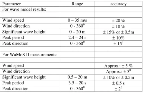
All support on the bridge is subject to the ‘Warning Dilemma’. The warning dilemma as presented in Table I depicts a high-level requirement for any system aiming to warn in critical situations. In a nutshell, safety critical systems shall issue warnings only if action is required, but always if action is required. Warnings issued if no action is required might increase the risk. Warnings not issued if action is required might have two reasons – either the system cannot assess a situation, or it malfunctions. If this occurs during operation the user confidence in the system decreases.
Table I: Warning dilemma (Courtesy of Arne Braathens, DNV) Action Action
required not required
Warning issued OK not OK
Warning not issued not OK OK
On the other hand, during the design phase of a ship a massive amount of numeric simulations are carried out using direct calculation tools. Basis for these calculations are the ship in its current design stage, the operational envelope of the intended service, and environmental data. As one result of these investiga-tions, limits of the operational envelope are determined, or the design is altered. Limits determined can be displayed in polar diagrams, giving limiting significant wave heights as a function of encounter angle and ship speed. The parameters of the polar diagrams are the wave length, the loading condition, and the exceedance of a certain threshold value (e.g. particular roll angle, accelerations at a certain position of the vessel, stresses in the structure).
Fig.1: Example of a polar plot. Loading condition, wave length, failure criterion and threshold fixed
DecisionUncertainty
actual sea surface in time and space around the locationof the vessel
numerical Sea Surface Generator Sea Surface Sensor Sea Surface Data
numerical Sea Surface Data
numerical Submode Load Analyzor(excitation, velocity, acceleration linear loads) numerical Motion Analyzor
numerical System Response Data
Input/ Output numerical
Submode Analysis Data Probability Calculator
Probabilities
Risk Level Generator Safety / Economic Risk Level Safety / Economic Risk Analyzor
(internally rerunning to evaluate RCOs)
RCOs Risk Picture
Man-Machine Interface
Safety Consequence Data Risk Aversion Data - Safety
INPUT OUTPUT
Wind Sensor Wind Data Water Depth Sensor Water Depth Data
actual water depth at the location of the vessel
actual wind velocity and direction at the location of the vessel
Ship data data
base Ship data
Ship Data Selector
Sub Mode failure mode thresholds Economic Consequence
Data Risk Aversion Data -
Economic
DecisionUncertainty
actual sea surface in time and space around the locationof the vessel
numerical Sea Surface Generator Sea Surface Sensor Sea Surface Data
numerical Sea Surface Data
numerical Submode Load Analyzor (excitation, velocity, accelerationlinear loads) numerical Motion Analyzor
Sub Mode failure mode threshold
numerical System Response Data
Input/ Output numericalSubmode Analysis Data Probability Calculator
Probabilities
Ship varying data Ship fixed data
Ship operational
data
Risk Level Generator Safety / Economic Risk Level Safety / Economic Economic Consequence Data Risk Analyzor
(internally rerunning to evaluate RCOs)
RCOs
Risk Aversion Data -Safety Risk Picture Man-Machine Interface Safety Consequence Data Preparation and calibration in mode 3 INPUT OUTPUT Wind Sensor Wind Data Water Depth Sensor Water Depth Data
actual water depth at the location of the vessel
actual wind velocity and direction at the location of the vessel
Risk Aversion Data -Economic
Ship Data Pr
eparator Ship data data base Ship data
Ship Data Selector
Using in mode 1 and mode 2 Preparation and calibration in mode 3
Sub Mode failure mode thresholds Economic Consequence
Data
Using in mode 1 and mode 2
Mode 1 - operation
Mode 2 - training
Mode 3 - design
ship specific mode 1 calibration and implementation of modules
and data blocks Ship specific limits and
thresholds operational envelope theory - phenomenological description of failures, assumptions, limits praxis - training in simulated environment without mode 1 implementation
operation with mode 1 implementation
operation without mode 1 implementation
praxis - training in simulated environment
with mode 1 implementation theory - risk based concept, limits of the system, use of the system
Fig.2: ADOPT process
The example in Fig.1 shows that in following seas at low speeds the vessel will exceed the set threshold value for the selected criterion already in small waves of 2 to 3 m significant wave height. Such diagrams
are generated during ship design and compiled into operational manual booklets. These booklets are made available to the crew in printed form. The challenge is to make this information available to the crew by making best use of modern information, knowledge, and IT tools. The objective then is to
Assist the master to identify and avoid potentially dangerous situations.
Obviously, one usesz state-of-the-art tools and techniques to achieve this objective, namely those found in the fields of risk–based decision making, sensing and modeling the environment, numerical simulations, handling of ship data, and Human-Machine-Interface (HMI). The ADOPT project is structured in these fields:
WP1: Definition of the criteria WP2: Environment WP3: Numerical simulation WP4: Ship data WP5: Man-machine interface WP6: Integration WP7: Validation
The result of ADOPT is not only hardware and software than can be installed on the bridge of a ship. In order to satisfy the requirements as listed in the Appendix, a process has been developed that covers ship design, training, and operation, Fig.2.
2 Approach
ADOPT has identified a number of high-level requirements for a decision support system (DSS), see Appendix. The requirements were derived from a Hazard Identification Session, and by a number of interviews with captains. Additionally, requirements resulted from state-of-the-art studies in the fields of environment, numerics, ship data, and HMI.
For assembling a system like the ADOPT system, expertise and subsystems are required from the fields of sensing of the environment, ship data handling, uncertainty modeling, motion simulation, probability calculation, and HMI. These subsystems are either mature, or available as systems under development. On the other hand, these systems come from different manufacturers. Consequently, a modular approach was chosen identifying all relevant systems and data sets with interfaces and functionalities. With these interfaces and functionalities, cross-platform implementation and exchange of components (e.g. due in-crease in knowledge) are possible. In addition, the modularity of the system provides an implementation independent system definition.
Typical decision support systems provide decision support based on probabilities. This support has a core deficiency: If undesired events are assessed concurrently, it is not possible to decide what action to take. It is not obvious, whether a probability – or better frequency – of large roll angles of 10−7per year is worse than a slamming frequency of 10−5. Risk as a decision making concept is established in IMO (2007). It is reasonable to use the same principles for decision support on a ship, as they are used for developments at IMO level. For these reasons, ADOPT uses risk as its decision metric. The other key issue in ADOPT is the process view, that links design to operation via training.
3 Result
ADOPT provides a process with the three major process elements: mode 3 – design
mode 2 – training mode 1 – operation
Decision support for mode 1 starts in mode 3. Mode 2 is required to convey the information generated in mode 3 to mode 1. Operation of a ship in mode 1 will be improved by mode 2 even without a specific computerized mode 1 DSS. A computerized mode 1 DSS will further improve the operation in mode 1 by given real time support, that might capture scenarios beyond the experience or capabilities of the crew.
Fig.2 identifies the main steps in the process – mode 3, mode 2, and mode 1 – and the process elements within the modes leading to the subsequent mode. The upper box represents the mode 3 – Design. The main elements are the identification of ship specific hazards with their limit states, and the identification of the operational envelope. Another task is the calibration and set-up of the ADOPT-DSS for the mode 1 use. Mode 3 links into both mode 2 – Training and mode 1 – Design. The function of the training is divided into two parts corresponding to the two possible modes of employ of a DSS in the mode 1 – Operation, with and without a hardware/software implementation on board. Fig.3 identifies the pro-cess elements within mode 3 that lead to specifically prepared data for use in mode 1, and specifically calibrated modules to be used in mode 1.
implementation for mode 1
Defines and calibrates modules in mode 1 Calibration in mode 3
Preparation Ship
Varying Data Preparation Ship Fixed Data
Identification ship specific hazards
(sub mode definition)
Ship specific mode 3 limit state threshold values (sub mode failure mode threshold) Identification ship/ operator specific economic consequences Identification operator specific risk aversion Identification ship/ specific risk control options Ship specific mode
3 limit state formulation (sub modes) Identification ship specific operational envelope
Ship specific mode 1 limit state threshold values (sub mode failure mode threshold) Ship specific mode
1 limit state formulation (sub modes) Preparation Ship Operational Data DecisionUncertainty
actual sea surface in time and space around the location of the vessel
numerical Sea Surface Generator Sea Surface Sensor
Sea Surface Data
numerical Sea Surface Data
numerical Submode Load Analyzor
(excitation, velocity, acceleration linear loads)
numerical Motion Analyzor
Sub Mode failure mode
threshold
numerical System Response Data
Input/
Output numericalSubmode Analysis Data Probability Calculator
Probabilities
Ship varying data Ship fixed data
Ship operational
data
Risk Level Generator Safety / Economic Risk Level Safety / Economic Economic Consequence Data Risk Analyzor
(internally rerunning to evaluate RCOs)
RCOs Risk Aversion Data -Safety Risk Picture Man-Machine Interface Safety Consequence Data INPUT OUTPUT Wind Sensor Wind Data Water Depth Sensor
Water Depth Data
actual water depth at the location of the vessel
actual wind velocity and direction at the location of the vessel
Risk Aversion Data -Economic
Ship Data Pr
eparator Ship data data
base Ship data
Ship Data Selector
Fig.3: Calibration of ADOPT system in mode 3 3.1 Mode 3 – Design
Of those given in the Appendix, the following requirements will be satisfied in mode 3: ‘1 – The DSS shall be modular.’
‘2 – The DSS shall be risk-based.’
‘5 – The DSS shall take into account the relevant uncertainties from all sources.’
‘6 – The DSS shall provide quality control regarding the reliability of the displayed information.’ ‘29 – The DSS shall display information of limitations in the displayed content.’
‘34 – The DSS shall be able to perform a self-assessment.’ ‘37 – The DSS shall be ship-specific.’
‘38 – The DSS shall be reliable.’
‘39 – The DSS shall resolve internal contradictions and provide consistent decisions support.’ Work carried out in mode 3 results in an intimate understanding of the ships performance in critical situ-ations. This knowledge can be made available to mode 1 by various means. Independently whether mode
1 is supported by a hardware/software implementation, a ship performance manual can be compiled. This manual describes the ship and the effect of selected Risk Control Options for the most critical scenarios. In addition, if a hardware/software implementation of the DSS is available to mode 1, the underlying data should be generated in mode 3. This ensures data consistency and process reliability.
3.1.1 Identification of operational envelope
The actual sea surface is represented by sea state data describing (as well as possible) the operational area of the vessel. Preferably, hindcast data is used, as this gives consistent wind and wave data covering a wide range of conditions. Based on the given environment and ship specific conditions, the added resis-tance in waves is calculated to determine the maximum speed possible in a seaway. During an optimiza-tion process (where the risk or frequency of a selected hazard is calculated) the operaoptimiza-tional envelope may be restricted due to economic considerations, e.g. advising the master to avoid significant wave height over a certain level or recommend speed and heading combination in heavy sea. The processing of these recommendations by the master requires proper training (mode 2).
3.1.2 Identification of ship specific hazards
The generic hazards identified so far in ADOPT and subject to implementation are: – Large amplitude roll motion (capsize)
– Loss of lashed cargo
– Loss of not secured cargo (cars/trucks, container) – Shift of cargo/ lashed Roro cargo
– Shift of cargo/ not secured Roro cargo (shift within cargo unit) – Large acceleration/ injuries
– Large acceleration/ reduced crew performance
– Green water (relative motion, damage to equipment/outfitting on deck) – Loss of course control
– Loss of propulsion
– Propeller racing (relative motion) – Wave bending moment
A hazard identification is strongly recommended for each specific installation of a DSS. 3.1.3 Ship specific limit state formulation
According to its definition, a Limit State is a ‘state beyond which the structure no longer satisfies the requirements’. A Limit State Function is a function of the basic variables, negative valued when the structural component fails, positive valued when the structural component is safe, Skjong et al. (1996). This definition is extended to include also arbitrary ship properties or failure mechanism (like submer-gence of ventilation ducts, shift of cargo, slamming, deck wetness, or ship capsize).
Limit states must be formulated for the identified, ship-specific hazards, i.e. the phenomenon must be mathematically formulated. In the easiest cases, analytical formulations (e.g. taken from Class Rules) might be taken. It is important to ensure that such a formulation is adequate for the specific vessel. Depending on the physics of a certain failure mode, the limit state formulation might involve complex simulations. Then, the limit state formulation can be applied in design (mode 3) only. To be able to assess these types of failure in operation as well, the limit state has to be calibrated to allow for mode 1 assessment. This calibration requires a limit state formulation that can be computed in mode 1, and a calibration of the respective failure threshold values.
An example is the combination of nonlinear simulations of ship motions, viscous CFD (computational fluid dynamics), and nonlinear FEM to calculate loads induced by slamming and the respective system response, namely the stresses within the steel structure. In mode 3, coupled fluid-structure interaction will be used to assess certain scenarios. These results are used to calibrate a mode 1 implementation, i.e. using relative motions and/or relative accelerations of ship and water.
3.1.4 Ship specific limit state threshold values
For the identified limit states, threshold values have to be determined. Using the above example of slam-ming, the deflections the steel structure can bear without failure is a ship specific threshold value. De-pendent on the calculation procedure this corresponds to a hydrodynamic pressure on the ship’s wetted surface which in turn is correlated to a relative velocity between water and hull at selected locations. In the design process, the equivalence between a structural based threshold value and ship motion based threshold as in the previous example may be developed for two purposes – optimization of the vessel with regard to the analyzed hazard and/or calibration for the mode 1 and 2. An optimization of a vessel with regard to a hazard implies a calculation of the risk or frequency of the ship specific hazard. During this step, the different thresholds are correlated. This equivalence can only be developed in mode 3, as mode 3 enables time for running necessary calculations and expertise for generation of math models and judging results of calculations.
The following example demonstrates the necessity of different limit state formulations and threshold classes for the same hazard dependent on the specific vessel. For the hazard ‘Propeller Racing’, the threshold value depends on the automation of the propulsion train and the main engine. If the automation enters shut-down mode if the revolutions increase and the moment decreases, propeller emergence and duration of the emergence jointly establish the threshold value. If the automation does not shut down the main engine, but continuously adjusts engine revolutions and delivered power, the frequency of this process is the threshold value. This is ship specific: If the automation is clever enough, the generic hazard ‘propeller racing’ might not be that important for some implementations, except for perhaps very extreme operational conditions.
It is suggested to have escalating threshold values for each limit state. I.e. the same hazard in its respective limit state formulation will have different consequences if different threshold values are exceeded. For example, if the hazard is ‘vertical accelerations leading to personnel injuries’, one threshold value is pertinent to ship crew, another – most likely smaller – threshold value is pertinent to passengers.
3.1.5 Ship specific limit state and threshold value calibration for mode 1 use
Some limit state formulations and corresponding threshold values cannot be used in the DSS mode 1 implementation. Two reasons prohibit this: the required computation time for the respective calculations and the lack of expertise to judge the results.
As in mode 1 no advanced calculations, such as viscous CFD load generation, can be performed, some ship specific limit state formulations and respective threshold values have to be calibrated in mode 3 for being used in mode 1. The calibration consists of two steps; the development of physical and ship motion related models and the determination of the related threshold values.
Using slamming as an example, the exceedance of stresses in the steel structure will be associated with phenomena that are representative, but faster to compute in mode 1. For example, characteristic relative velocities between critical points of the hull and the water could serve as a representative formulation. The threshold values for mode 3 (yield stress of the steel structure) is correlated to the threshold values for mode 1 (relative impact velocity).
3.1.6 Identification of operator specific economic consequence data
The list of generic hazards given in section 3.1.3 has to be made concrete and to be made both ship and operator specific. Afterwards it is necessary to assign a monetary consequence to the respective hazard. This gives the basis for the risk analysis that is carried out within the framework of an ADOPT-DSS. For example, the hazard ‘Shift of cargo/ not secured Roro cargo (shift within cargo unit)’ is made specific with the formulation ‘The contents of trailers on the leg Gothenburg – Immingham are shifted due to ship motions’ as a first step.
The next step is to assign a monetary consequence to this event. A guideline for defining consequence is not to have the worst case scenario in mind, but to consider the ‘worst credible consequence’.
In this example, a worst case might be damaging the content of a trailer containing time critical expensive goods (e.g. pharmaceuticals) that are sent once in a couple of years. The worst credible consequence could be having the high-value goods in mind that are sent with the ship on a regular basis.
This process element (identification of operator specific economic consequence data) yields a list with the relevant hazards in their specific formulation, associated with the respective costs. Note that generic hazards and/or generic consequence data might lead to wrong decision support.
3.1.7 Identification of operator specific economic risk aversion
Risk aversion is expressed using measures for consequences drawn versus measures for likelihoods. Both the quality and the quantity should be in a format that reflects the operators’ way of thinking. The scale both of frequency and consequences depends on the specific business. For example, an operator might think in terms of the duration of a roundtrip, the time period for internal accounting, up to the envisaged time horizon of the operation. For consequences, a similar approach should be chosen. Most importance is that monetary consequences are relevant and understandable to the operator.
Having the relevant scales for likelihoods and consequences (and their respective subdivision into bands), the next step is to identify those areas in the frequencies/consequences risk matrix, that are acceptable or intolerable for the operator. Acceptable is any combination of likelihood and consequences that does not matter to the operator. Intolerable is any combination that the operator cannot live with. The remaining part in between is the ALARP (As low as reasonably practicable) area, where hazards lying in that area will be subject to a cost-benefit analysis (CBA). Only if the benefit exceeds the costs, hazard allocated in that area will be subject to risk reduction.
3.1.8 Identification of ship specific risk control options
Risk Control Options generally available to a sailing vessel are change of course, change of speed, change of status of motion stabilizing devices, change of ballast, or combinations of the above. During design, further RCO are available, like hull form design, specific layout of motion stabilizing devices, selection and layout of equipment, etc.
Besides the selection and application of RCO pertinent to design, a particular task within mode 3 is the analysis of the applicability and efficiency of the RCO available in mode 1. This task is closely linked to what is described in section 3.1.9.
3.1.9 Preparation and calibration of ship data database for mode 1 and mode 2
Typical design work is the preparation of the stability documents for intact stability, the stability book-let. This document is based on contract loading conditions. Additional loading conditions covering the operation are carefully prepared and used in the subsequent process elements.
The process element of preparing representative operational loading conditions covers the definition of ship varying data (particularly masses of payload) characterizing a particular loading condition. This
step includes correct modeling of masses (including their position in longitudinal, lateral and vertical dimension) and free surfaces.
When the loading conditions are defined, the seakeeping model (i.e. the mass model with mathematical representation of the corresponding wetted hull surface) is set up. As these models will be used by non-experts in an automated mode, this process element is critical.
In this part of the process, all three data groups (ship operational data, ship varying data, ship fixed data) are first generated for those conditions that are relevant for mode 1. This creates three dataset with known uncertainties. These data sets are then compiled into one database, which is accessible in mode 1. By this method the unknown uncertainties in the loading data from the loading computer in operation are overcome and replaced by quantifiable uncertainties.
3.2 Mode 2 – Training
The general approach in the training mode of ADOPT is not only the familiarisation with the system itself but also to give advise on the background of phenomena (like parametric rolling), as the purpose of the DSS only can be captured when the theoretical foundation is available. By this approach, the training does not only customise the user on the system but also contributes to an improved situational awareness of the risks in specific sea states.
The training concept consists of two modules with two sessions each, starting with general ship theory. Since the ADOPT-DSS is ship specific, the theory will afterwards be consolidated by exercises in the simulator demonstrating the vulnerability of the specific ship in particular seas. In the next session, the crew will be familiarized with using the DSS. This again starts with the theoretical description how the DSS works, which are its limitations, which are its modules, and in which situations it can help. Afterwards, in the final module, the user will be customised in a simulator environment to get experience in using the system and improve his behaviour in critical situations.
3.2.1 Familiarization with the ship, theory
This module starts by providing the theoretical background on ship behaviour in general. It explains what determines ship motions and how ships will move under specific conditions. It gives an introduction into ‘new’ phenomena (like parametric roll) and how these phenomena are determined. It makes proposals how (without any technological help) the master can identify the risk of his current situations and how he generally could avoid high risks. As the DSS is ship-specific, this module has a second part in which the theoretical background is applied to the specific ship. This part employs the experience gained during the design of the ship and presents critical conditions for that specific ship (in aspects of loading, sea state, etc.) and how they could be avoided. It gives detailed insight into that ship and presents recommendations how this ship should be operated in different situations.
3.2.2 Familiarization with the ship, practice
In this module, the experience gained in the first module is illustrated in practical exercises in a simulator environment. The main learning objective is the consolidation of the theoretical knowledge. Therefore, selected dangerous situations are demonstrated to illustrate how the specific ship will behave under those conditions. Afterwards strategies will be trained how to avoid these situations and how to operate the ship in them.
3.2.3 Familiarization with a mode 1 DSS, theory
After having laid the fundamentals in the previous modules, the student needs to be trained on how to the DSS. The DSS covers only some risks and has a specific approach. Thus the user needs to grasp the philosophy of the DSS in order to understand when and how the DSS can help him. Therefore a clear introduction into the system is given, addressing its risk based approach, which hazards are covered and
what limitations the system has. This is complemented by an introduction into the application of the system and how the HMI needs to be used.
3.2.4 Familiarization with a mode 1 DSS, practice
The final module is again a practical exercise in a simulator environment, this time with the focus on training to sail the ship in difficult conditions with the assistance of a DSS. Several scenarios are devel-oped in which the student can prove that he knows how to deploy the DSS to achieve a status with lower risk. It is tested whether the user is able to assess situations right and derive the right conclusions. He also has to prove that he knows the limitations of the DSS and can identify the situations in which the DSS cannot assist him.
3.3 Mode 1 – Operation
Of those given in the Appendix, the following requirements will be satisfied in mode 1: ‘1 – The DSS shall be modular.’
‘3 – The DSS shall support real-time decision making.’
‘4 – Supported by a DSS, the master shall improve his decision making under uncertainty.’ ‘7 – Decision support shall have a time range of about one watch.’
‘8 – The DSS shall operate on a ship while sailing.’ ‘9 – The DSS shall be operated and used by a ship’s crew.’
‘19 – The DSS shall take into account extreme environmental conditions.’ ‘20 – The DSS shall take into account multiple wave systems.’
‘24 – The DSS shall avoid misinterpretation of displayed information.’ ‘25 – The DSS shall avoid display of wrong information.’
‘26 – The DSS shall be robust.’
‘29 – The DSS shall display information of limitations in the displayed content.’
‘32 – The DSS shall warn the user if risks arising from the identified hazards are beyond negligible.’ ‘34 – The DSS shall be able to perform a self-assessment.’
‘37 – The DSS shall be ship-specific.’
‘39 – The DSS shall resolve internal contradictions and provide consistent decisions support.’ 3.3.1 Mode 1 DSS without hardware and software support
Without support by a hardware/software implementation, mode 1 depends both on mode 2 – familiar-ization with the ship in theory and practice – and the availability of guidance from mode 3 – operators guidance. The requirements No. 3, 4, and 24 are relevant only in that sense, that access to supporting information (e.g. operator’s manual) must be prepared to allow easy access.
Requirement ‘4 – Supported by a DSS, the master shall improve his decision making under uncertainty.’ is ensured by training in mode 2. This training provides the master with the expertise necessary to im-prove his decision making. Requirements No. 9, 24, 25, and 37 remain as relevant for operating a ship without a hardware/software implementation. These requirements have to be directly addressed in the preparation of a ship performance manual, and the set-up of training courses. Requirement No. 25 is subject to Quality Assurance in mode 3.
3.3.2 Mode 1 DSS with hardware and software support
Main components of the onboard installation are a wave sensor, a ship data database, fast and accurate motion prediction tools, and a Man Machine Interface (MMI). Within ADOPT, a wave radar is used for sensing the environment. The reason is that only by using a radar it is possible to satisfy requirement No. 19. The numerical motion simulation tools are linear frequency domain ship responses for economic