HAL Id: hal-02130058
https://hal.archives-ouvertes.fr/hal-02130058
Submitted on 15 May 2019
HAL is a multi-disciplinary open access
archive for the deposit and dissemination of
sci-entific research documents, whether they are
pub-lished or not. The documents may come from
teaching and research institutions in France or
abroad, or from public or private research centers.
L’archive ouverte pluridisciplinaire HAL, est
destinée au dépôt et à la diffusion de documents
scientifiques de niveau recherche, publiés ou non,
émanant des établissements d’enseignement et de
recherche français ou étrangers, des laboratoires
publics ou privés.
Disturbance and recovery in high speed (110) cleavage
in single crystalline silicon
Lv Zhao, Meng Wang, Anne Maynadier, Daniel Nelias
To cite this version:
Lv Zhao, Meng Wang, Anne Maynadier, Daniel Nelias. Disturbance and recovery in high speed (110)
cleavage in single crystalline silicon. Journal of the European Ceramic Society, Elsevier, 2018, 38 (4),
pp.1038 - 1045. �10.1016/j.jeurceramsoc.2017.12.035�. �hal-02130058�
(will be inserted by the editor)
Disturbance and recovery in high speed (110) cleavage in
1
single crystalline silicon
2
Lv Zhao · Meng Wang · Anne Maynadier ·
3
Daniel Nelias
4
5
Received: date / Accepted: date
6
Abstract Stress perturbations and material defects can significantly affect the
7
fracture initiation and propagation behaviors in brittle materials. In this work, we
8
show that (110) [110] cleavage in silicon deflects onto (111) plane in the presence
9
of contact stresses. The deflection is however not permanent as the crack returns
10
to the (110) plane after a certain length of propagation, even in the case where
11
the crack velocity is up to 78% of the Rayleigh wave speed. The recovery behavior
12
indicates that the (110) [110] cleavage is invariably prevailing when perpendicular
13
to the maximum stress. Following this indication, it can be concluded that the
14
observed (110) [110]–(111) deflection in previous literature is most likely driven by
15
the external disturbance rather than the crack velocity induced toughness
evolu-16
tion. We also highlight that the extra energy for the (110) recovery is minimized
17
at the expense of a large propagation distance upon the plane switch.
18
Keywords Fracture, silicon single crystal, crack deflection, high speed
propaga-19
tion
20
1 Introduction
21
Crystalline silicon occupies a dominant place in the current photovoltaic (PV)
22
applications. However, due to the brittle characteristic, catastrophic failure of the
23
solar cells eventually leads to large power loss and severly impacts reliability and
24
Lv Zhao
Univ Lyon, INSA-Lyon, CNRS UMR5259, LaMCoS, F-69621, France E-mail: lv.zhao08@gmail.com
Meng Wang
Univ Lyon, INSA-Lyon, CNRS UMR5259, LaMCoS, F-69621, France Anne Maynadier
Univ Bourgogne Franche Comt´e, FEMTO-ST Institute, Departement of Applied Mechanics, CNRS/UFC/ENSMM/UTBM, F-25000, France
Daniel Nelias
Univ Lyon, INSA-Lyon, CNRS UMR5259, LaMCoS, F-69621, France E-mail: daniel.nelias@insa-lyon.fr
durability of the Si-based PV technology [1,2]. A full understanding on the fracture
25
mechanism in silicon is necessary for the design and the use of PV devices. Albeit
26
continuous investigations have been performed, the fracture behaviors, particularly
27
those manifest during the dynamic propagation, still involve an open discussion
28
[3, 4].
29
The fracture in silicon mainly takes place along the low energy planes of (110)
30
and (111) [5–8]. The crack velocity in silicon is generally high because of the low
31
fracture toughness and the absence of plastic dissipation under the brittle-ductile
32
transition temperature [9–11]. Among the velocity related fracture phenomena,
ve-33
locity gap recieved a significant attention. Experiments showed that low (<<2000
34
m/s) steady state crack velocity was somehow forbidden [6, 12], conversely to the
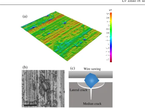
35
theoretical one that can vary from zero to the Rayleigh wave speed (CR) according
36
to the linear fracture mechanics. Molecular dynamics simulations explained this
37
threshold as a consequence of a localized phase transformation in the vicinity of
38
the crack tip [13] that delays the fracture initiation. However, a recent work
sug-39
gested that the velocity gap should not be considered as an universal indication,
40
since an extremely low speed (in 100 m/s speed range) cleavage along (110) can
41
stably take place via kink formation and advance under a suitable temperature
42
and some specific loading conditions [14]. This new finding reveals that the
exter-43
nal conditions need to be carefully considered when investigating the fracture in
44
silicon.
45
As one of the main crack paths in single crystalline silicon, (110) cleavage has
46
been substantially investigated in the previous literature [12,15,16]. Pioneer works
47
highlighted that (110) cleavage involved a directional anisotropy [8, 15]. The crack
48
propagation in [001] direction on the (110) plane (denoted as (110) [001]) could
49
not be achieved and the crack systematically switched to (111) plane [7]. This
50
deflection mechanism was elucidated by molecular dynamics simulations [8, 15],
51
which showed that the atom debonding suffered from prounced lattice trapping
52
when heading (110) [001].
53
Conversely to the (110) [001] cleavage that would yield a global plane
deflec-54
tion, (110) [110] crack manifests with a much higher stability [12]. Mirror-like
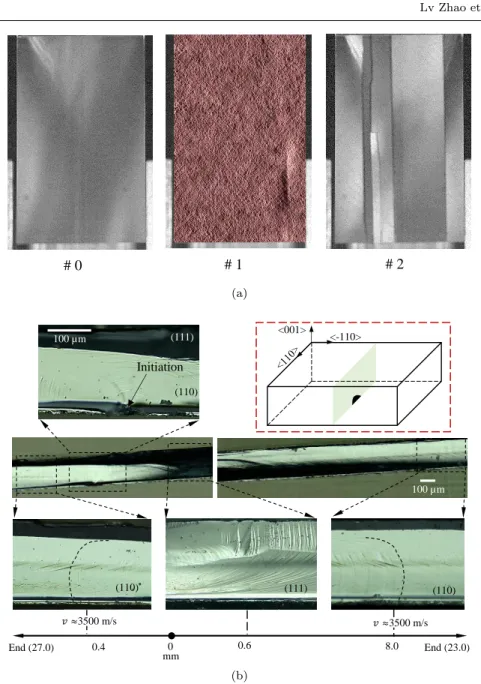
55
morphology was observed in the middle of the (110) fracture surface during a high
56
speed propagation (3000 m/s) under tension, accompanied by tiny (111) facets
57
near the specimen surface [12]. This stability was also evidenced in 4-line
bend-58
ing tests (with the crack propagates in the middle of the contact span), in which
59
the (110) plane was dominant up to the propagation velocity of 3700 m/s [16].
60
However, 3-line bending conditions (with the crack propagates underneath the
61
punch roller) led to disparate fracture scenarios [17, 18]. In these experiments,
62
large (110)–(111) plane deflection was encountered when the crack velocity
ex-63
ceeded 2000 m/s. Regarding the explanation for the deflection phenomenon, the
64
authors conjectured that the (110) dynamic toughness would increase faster than
65
that of the (111) plane when the crack speeds up, so that till a certain velocity (for
66
instance 2900 m/s in the [110] direction) the (110) plane becomes no longer the
67
prevailing crack path in a high speed case [17, 19]. After that, a thermal phonon
68
emission machanism was postulated, which permitted to rationalize the
aforemen-69
tioned conjecture [20]. However, the plane switch theory derived from these 3-line
70
bending tests might not be generalized, since i) the presence of the external
per-71
turbations,i.e.the contact stresses was not taken into account, and ii) (110) [110]
72
cleavage was revealed stable regardless of the crack velocity (1200 m/s–3700 m/s)
when subjected to pure bending load [16]. From these two attributes, it brings
74
the need for a revision of (110) [110] cleavage, and the fracture stability should
75
be assessed with the careful measures of external perturbations during high speed
76
crack propagations.
77
Therefore, in the present work, we investigate the (110) [110] initiation and
78
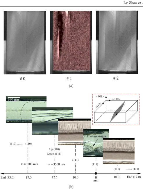
propagation behaviors in the presence of the contact conditions and also with
79
various micro-crack geometries. 4-line bending tests are performed using single
80
crystalline silicon wafer without pre-existing cracks. The absence of pre-cracks not
81
only favors the initiation under the punch roller, but also promotes large crack
82
velocity. High speed camera is used to monitor the first crack, then fractographic
83
anaysis is carried out to identify the cleavage plane and to determine the crack
84
velocity during the propagation. It is observed that the crack tends to switch
85
to the (111) plane at the early propagation stage. However, the disturbance is
86
not permanent as the crack systematically recovers on the (110) plane after a
87
certain length of propagation. Moreover, the recovery occurs over an extremely
88
high velocity (3500 m/s i.e. 0.78CR). This indicates that the (110) [110] crack
89
path is more energetically favorable than the (111) 1 one in both slow and rapid
90
propagations, which is contradictory to the aforementioned evolution mechanism
91
of the fracture toughness.
92
2 Experiments
93
2.1 Single crystalline silicon plate
94
Solar grade single crystalline silicon was used. The specimens were cut from
as-95
sawn silicon wafers. The dimension of the specimens is 50×50×0.2 mm. The crystal
96
is oriented such that two [110] directions are parallel with the specimen edges and
97
one [100] direction perpendicular to the specimen surface.
98
As shown in Fig. 1, the specimen surface involves periodic cutting traces and
99
also some hollows (see Fig. 1(a)). The hollows can be more clearly evidenced in
100
Fig. 1(b). This surface morphology is attributed to the diamond wire sawing
101
process where the hard diamond particles indent the new created silicon surface
102
and lead to lateral cracks (manifesting as hollows in Fig. 1(b)). The interaction
103
is shown in the schematic Fig. 1(c). Along with the lateral cracks, sharp median
104
cracks likely nucleate and extend into the material. This kind of cracks, which are
105
barely visible under microscope, have been monitored by X-ray image and shown
106
to have a depth of 10µm range [21]. These micro-cracks are randomly distributed
107
on the specimen surface.
108
2.2 4-line bending tests
109
A 4-line bending set up was used to load the samples til fracture. The silicon
110
plate was placed such that the (110) [110] was right aligned with the punch roller,
111
see Fig. 2. In this configuration, the (110) plane would be the most solicitated
112
as it is perpendicular to the maximum stress. The inner and outer contact spans
113
Median crack Wire sawing Lateral crack 10 µm (a) (b) (c)
Fig. 1: Morphology of the specimen surface. Distribution of cutting traces and hollows (a), zoom on one hollow (b), schematic drawing of lateral and median cracks induced by diamond particle-material interaction (c).
are 21 mm and 40 mm, respectively. Quasi-static loading conditions with a strain
114
rate in the order of 10−6/s were ensured by a LLOYD-Ametek LFPLUS
electro-115 mechanical machine. 116 Specimen Mirror 45° 40 mm 21 mm 45° High speed camera
55 mm <110> <-110> < 0 0 1 > 26 mm Mirror support
2.3 Fracture monitoring
117
A high speed camera (Photom V710) was set up in order to capture the fracture
118
initiation and propagation. Given that the initiation would most likely occur under
119
the punch roller, the camera was set as it could cover the whole inner contact
120
region, see Fig. 2. As a compromise, the frequency for image acquisition was set
121
to 49000 Hz at the expense of the image resolution (512×256 pixels).
122
Fractographic analysis was carried out after each test to evaluate in a
post-123
mortem way the cleavage plane as well as the crack velocity. The crack velocity
124
estimation was based on our former work [16], in which a correlation between the
125
crack surface morphology and the propagation velocity was established. In this
126
way, the resolution for velocity measurement was down to micro-scale along the
127
propagation path and the steady state of the crack propagation could be easily
128
identified.
129
3 Results
130
The results will be presented in two parts, in each a representative case is
ad-131
dressed. The first one shows the contact perturbations, the second one exhibits
132
the effect induced by the orientation of the fracture origin. For each part, the
frac-133
ture initiation is highlighted with the high speed imaging technique and the local
134
crack propagation is disclosed with the fractographic analysis. A general discussion
135
on the fracture behavior will finally be carried out in the next section.
136
3.1 Contact perturbations
137
The fracture process of the first case is presented in Fig. 3a. The image #0
rep-138
resents the last photo before cracking. The image #1 monitors the first crack, it
139
involves a subtraction beteween the first photo after cracking and #0. The image
140
#2, which is the second photo after cracking, shows multiple cracks right after
141
the fracture initiation. From #1, it can be noticed that the first crack nucleates
142
and propagates straightly right underneath the punch roller. The image #2
re-143
veals that secondary cracks are curved and involve some branching instabilities.
144
This multiple cracking feature is attributed to a burst of flexural waves that are
145
generated upon the sudden release of the curvature of the bent specimen [22]. The
146
flexural waves then lead to local overstresses and initiate secondary cracks.
147
According to the obervations on the first crack, the fracture initiation spot
148
and the cleavage planes during the propagation are reconstructed and presented
149
in Fig. 3b. One can notice that the crack initiates from a sub-surface micro-crack
150
which should be induced by the wire sawing. The fracture origin is located near the
151
half length of the specimen, so the crack propagates in two opponent directions.
152
The fracture history for this case is outlined below:
153
– The fracture initiation takes place on the (110) plane. Very smooth fracture
154
surface can be noticed close to the initiation spot, as shown in the schematic
155
drawing in Fig. 3b. This indicates that the micro-crack is oriented nearly
par-156
allel to the (110) plane, which ensures a small mismatch between the fracture
157
origin and the very beginning cleavage path.
# 0 # 1 # 2 (a) (110) (111) ) (110) (110) ) (110) Initiation (111) ) (110) End (23.0) End (27.0) 0.4 0 mm 0.6 8.0 𝑣≈3500 m/s 𝑣≈3500 m/s <001> <-110> 100 µm 100 µm (110) (b)
Fig. 3: Crack deflection and recovery under contact perturbations. First crack monitoring (a), and fractographic reconstruction of the crack initiation and prop-agation (b). The dotted curved lines in (b) represent the Wallner lines.
– The crack switches to a (111) plane after a very short propagation to the right
159
side, while it remains on the (110) plane during the subsequent propagation.
160
The deflection part manifests as a black zone on the fractography, as can be
161
noticed in the long fractographic images in Fig. 3b.
– After a propagation of about 8 mm to the right side on the (111) plane, the
163
crack returns to the initial (110) plane and then propagates in a steady state.
164
The steady state is clearly indicated by the constant shape of the Wallner
165
lines [16], see Fig. 3b.
166
– From the morphology of the fracture surface, one can infer that the steady
167
state crack velocties are close for both sides, which are equal to about 3500
168
m/s. This velocity represents 78% of the Rayleigh wave speed.
169
The global fracture path for the present case is illustrated in Fig. 4 to show
170
the deflection behaviors. The deflection first nucleates when the crack extends to
171
the compression side of the specimen, this is also where the contact would have
172
strong perturbations in the stress field. This deflection then quickly develops to the
173
tensile side until the (111) plane covers the whole fracture surface. Therefore, it
174
can be concluded that the contact significantly influences the (110) [110] cleavage
175
and utimately leads to a global plane deflection. This conclusion can explain why
176
(111) cleavage was encountered in 3-line bending tests [17].
177
(110) (111) (110)
Fig. 4: Overall fracture path under the contact perturbations.
However, the (110) [110]-(111) deflection is not permanent. According to the
178
observations in the present work, the crack recovers the (110) plane after a certain
179
length of propagation. This recovery was not observed in the previous 3-line
bend-180
ing tests. Interestingly, with other 3 similar tests, it is found that the recovery is
181
repeatable and always takes place at a distance around 8 mm from the initiation
182
point.
183
3.2 Fracture origin orientation
184
The present section adresses the second case in which the effect of the fracture
185
origin orientation is involved. The identification of the first crack is presented
186
in Fig. 5a. The numberings #0, #1 and #2 have the same representations as
187
explained in section 3.1. Here, in the image #1, several cracks can be noticed.
188
Among them, the left one, which is right underneath the punch roller, is the
189
longest and therefore considered as the first crack.
190
Focusing on the first crack, the fracture initiation and propagation are disclosed
191
by fractography, as can be noticed in Fig. 5b. The fracture origin involves also the
192
sub-surface micro-crack, which is located 17 mm away from one of the specimen
193
edges. Following observations are exhibited which allow an overview on the fracture
194
process:
195
– The crack initiates on the (111) plane. This crack nucleation is due to the fact
196
that the micro-crack orientation is closer to the (111) plane, as indicated in
197
the schematic drawing in Fig. 5b. Yet the contact stresses are not relevant,
198
knowing that the fracture origin is on the tensile side of the specimen and
# 0 # 1 # 2 (a) 0 End (17.0) 10.0 12.5 17.0 End (33.0) 10.0 mm 𝑣 ≈3500 m/s (110) (111) (111) (111) Up (110) Down (111) (110) …… …… (111) 𝑣 ≈3500 m/s <001> <-110> Fracture origin 100 µm (b)
Fig. 5: Crack deflection and recovery under contact perturbations as well as (111) oriented fracture origin. First crack monitoring (a), and fractographic reconstruc-tion of the crack initiareconstruc-tion and propagareconstruc-tion (b). The dotted curved lines in (b) represent the Wallner lines.
thus far from the contact perturbations. The crack initiation involves the main
200
difference between the present case and the one presented in section 3.1.
201
– The crack propagates along the (111) plane to the right side at a quite constant
202
velocity,i.e.in its steady state, till reaching one free edge of the specimen. The
203
steady state is revealed by the morphology of the (111) instabilities [23, 24], as
shown in the right image in Fig. 5b. The length of the trajectory is about 17
205
mm.
206
– To the left side, the crack initially continues with a steady state (111) cleavage.
207
Then, it begins to progressively deflect onto the (110) plane after a propagation
208
length of 12 mm. The deflection is finished at about 17 mm away from the
209
initiation point. The crack then propagates stably on the (110) plane until it
210
reaches the other specimen edge.
211
– Thanks to the Wallner line shape, the velocity is estimated around 3500 m/s
212
for the (110) part, which reaches nearly 78% of the Rayleigh wave speed. The
213
velocity cannot be inferred on the (111) plane, as the Wallner lines are not
214
noticeable because of the surface instabilities.
215
The whole crack path for the present case is schematized in Fig. 6. Since both
216
the contact perturbations and the fracture origin-(110) plane mismatch are present
217
in this case, the (111) part is much longer (17 mm) than that in the case where
218
only the contact perturbations are involved (8 mm), see Fig. 3b. It should be noted
219
that the difference is not related to the crack velocity, as the steady state velocities
220
are very close in both cases.
221
(111) (110)
Fig. 6: Overall fracture path under the contact perturbations as well as (111) oriented fracture origin.
Despite of the strong perturbations, the crack jumps to the (110) plane after
222
a long propagation. It should be noted that the deflection process in Fig. 6 is
223
almost the same as that presented in Fig. 4. It begins from the upper portion of
224
the fracture surface and then develops towards the lower portion until the (110)
225
plane covers the whole fracture surface. This deflection behavior will be discussed
226
in the following section.
227
4 Discussion
228
Albeit the (111) plane has the smallest fracture toughness (Γ(111)=2.88 J/m2),
229
in the present loading configuration (see Fig. 2), the fracture energy dissipation
230
(Γ(111)∗ =3.54 J/m2) is however larger compared to the (110) plane (Γ(110)∗ =3.46
231
J/m2) because of the 35.6◦ inclination (see Figs. 3b and 5b). Thus, the (110)
232
plane is dominant in low speed fracture (≈1000 m/s), as highlighted in previous
233
works [16–18]. Nonetheless, it still remains unclear on the fracture mechanism in
234
the high speed cases, considering different fracture paths reported when the crack
235
velocity exceeds 2000 m/s [16, 17]. In this work, it has been shown that the crack
236
either stably propagates along the (110) [110] path or switches from the (111) plane
237
to this path at very high velocities (>3000 m/s). It can thus be concluded that the
238
(110) [110] cleavage remains energetically prevailing compared to the (111) one in
239
very high speed cases. In the one hand, this conclusion is coherent with our former
work [16] in which it was found that in the absence of perturbations the crack
241
always chooses the (110) plane for a large range of crack velocites [1200 m/s–3700
242
m/s]. In the other hand, the dynamic toughness evolution proposed in the previous
243
literature [17, 19] cannot be generalized since it cannot be substantiated by the
244
fracture behavior revealed in our former work [16] as well as the present one.
245 (a) (b) (c)
𝑣
𝑚𝑎𝑥𝑣 ≈ 0
𝜏
𝜎
𝑛 (111) (111) (110) (111) (110)𝑣
𝑚𝑎𝑥𝑣 ≈ 0
Fig. 7: (111)-(110) deflection. The crack propagates on the (111) plane under bending (a), possibility of deflection from the lower portion (b), and possibility of deflection from the upper portion (c).
As revealed through the experimental results, the contact effect and the (111)
246
oriented defect drive the crack to deflect or initiate on the (111) plane. Then a
247
recovery to the (110) plane takes place as the crack propagates far away from
248
the perturbation origin. However, the (111)–(110) deflection needs extra energy.
249
This can be assimilated to a grain boundary crossing. Previous studies have
250
shown that when a crack switches from one grain to the adjacent one, the
mis-251
orientation between the two cleavage planes toughens the plane ahead the grain
252
boundary [25]. In this sense, if the deflection is instant or very short, the (110)
253
plane will become no longer favorable since it is toughened due to a rotation of
254
35.6◦(Γ(110)∗∗ =Γ(110)∗ /cos(35.6◦)=4.25 J/m2compared toΓ(111)∗ =3.54 J/m2).
There-255
fore, in order to avoid the strong toughening induced by the sudden plane change,
256
the (111)-(110) deflection involves a long process. As indicated in Fig. 4 and Fig. 6,
257
the deflection takes place first in the upper portion of the fracture surface, where
258
the crack velocity is very low, and then extends to the lower portion, where the
259
crack velocity is much higher, until the (110) dominates the whole crack path. The
260
extension covers a propagation length of about 5 mm for both cases presented in
section 3.1 and 3.2. This indicates that the (111)-(110) deflection is likely
inde-262
pendent of the previous propagation history.
263
Why the (111)-(110) deflection initiates from the low speed portion? Indeed,
264
when the crack switches from the (111) plane to the (110) one under bending, there
265
exist two possibilities, as illustrated in Fig. 7. One is that the deflection initiates
266
from the lowest point, where the local velocity coincides with the global velocity
267
and is the largest, see Fig. 7(b), the other is from the highest point, where the local
268
velocity is almost zero, see Fig. 7(c). Assuming that the deflection is instataneous,
269
for the first possibility, the crack needs to rotate twice 90◦, while a single rotation
270
of 35.6◦is involved for the second one. This clearly shows that the deflection will be
271
much easier to take place from the upper portion in terms of avoding large angle
272
mismatch during the deflection. Moreover, when the deflection begins from the
273
highest point along the crack front, the deflection is naturally progressive as the
274
lower part advances faster and will not be immediately affected by the deflection
275
induced stress rearrangement. The deflection process is shown in the schematic
276
illustration Fig. 8, which permits a full analysis on the local deflection behavior.
277
Takingθas the angle between the local crack velocity direction and the horizontal
278
direction on the (111) plane, the local velocity direction along the crack front, as
279
indicated by the dotted arrows in Fig.8, can be expressed as:
280
V= [cos(θ), sin(θ),0] (1)
When the deflection towards the (110) plane happens at any point of the crack
281
front, the local velocity direction, as indicated by the solid arrows in Fig.8 becomes:
282
V0= [cos(θ), sin(θ)cos(35.6◦), sin(θ)sin(35.6◦)] (2) Therefore, the local deflection angle can be expressed in the function of θ,
283
which is also linked to the position along the crack front, as following:
284
α=acos(cos(θ)2+sin(θ)2cos(35.6◦)) (3) As the deflection extends to the lower portion i.e. θvaries from 90◦to 0◦, the
285
deflection angle diminishes until zero at the lowest point, as can be noticed in
286
Fig.9. At the same time, the local velocityvlincreases from zero to the maximum
287
value vmax which is also the global crack velocity, as drawn in Fig.9. The local
288
velocity is calculated according to the following approximation:
289
vl=vmaxcos(θ) (4)
Thanks to to the Freund condition [26], the energy balance during the crack
290
propagation is well established:
291
GS =
ΓDCR
CR− v
(5) where GS denotes the static strain energy release rate,ΓD represents the
dy-292
namic toughness,CRandvare the Rayleigh speed and the crack velocity,
respec-293
tively.
294
It can be noted that higher the crack velocity is, larger the energy dissipation.
295
The relationship can be noticed in Fig. 9. As the deflection angle decreases along
296
with the local velocity increases, the deflection process that described in Fig.8
(a) (b) (c) (110) (110) (110) (111) (111) (111) x y z
Fig. 8: Schematic process of the (111)-(110) deflection. The crack deflects from the upper portion (a), then it continues to deflect towards the lower portion (b) and (c). The dotted arrows indicate the atom debonding directions upon deflection and the solid arrows stand for the atom debonding directions if the crack remains on the (111) plane.
allows to minimize the extra energy dissipation to jump from the (111) plane to
298
the (110) one. It should be noted that if the deflection starts from the lowest
299
point, the overall dissipated extra energy for plane switch will be much higher,
300
this in turn will strongly decrease the global crack velocity. In other words, the
301
crack deflects from the highest point so that the global crack velocity would not
302
be significantly affected.
303
To the best of the authors’ knowledge, this is the first work showing both the
304
(110)–(111) and the (111)–(110) deflections in the fracture process in silicon. The
305
underlying mechanisms are however different for these two opponent plane switch
306
scenarios. More importantly, the results in the present study raise an open
discus-307
sion on the previous literature works in which dynamic toughness evolution was
308
assessed [17]. Note also that this study is mainly focused on high speed cracking,
309
which corresponds to large fracture stress and thus large contact force. In the
fu-310
ture, the investigation can be completed by other experiments in which controlled
311
fracture orgin size can be ensured to have variant crack propagation velocities.
0 5 10 15 20 25 30 35 40 0 15 30 45 60 75 90 D efl ect io n angl e (° ) (°) 𝜃 [110] [001] 0 0.1 0.2 0.3 0.4 0.5 0.6 0.7 0.8 0.9 1 𝑣/ 𝑣𝑚𝑎𝑥 𝜃
Fig. 9: Deflection angle and local crack velocity evolution along the crack front under bending. The deflection refers to the (111)–(110) cleavage plane switch.
5 Conclusion
313
In this work, the (110) [110] cleavage in silicon has been investigated in the presence
314
of contact perturbations as well as including various fracture origin geometries. It
315
has been shown that the contact can easily lead to (110)–(111) deflection, which
316
however was previously considered as a consequence of high speed propagation.
317
Albeit the external perturbations deviate the crack from the most favorable path,
318
(111) plane cannot be permanently maintained and the fracture process involves a
319
recovery to (110) [110] scenario during the propagation. This work highligts that
320
the dynamic toughness of the (110) plane should not increase faster than that of
321
the (111) plane until 78% of the Rayleigh wave speed. The (110) plane recovery
322
initiates from the lowest velocity point and progressively extend to the highest
323
velocity point in order to minimize the extra energy dissipation for the deflection.
324
Acknowledgment
325
The authors thank the French research agency ANR for partial funding through
326
the DURASOL Equipex project.
327
References
328
1. M. K¨ontges, I. Kunze, S. Kajari-Schr¨oder, X. Breitenmoser, B. Bjørneklett, Sol. Energy
329
Materi. Sol. Cells 95, 1131 (2011)
330
2. M. Paggi, I. Berardone, A. Infuso, M. Corrado, Sci. Rep. 4, 4506 (2014)
331
3. M. Adda-Bedia, R.E. Arias, E. Bouchbinder, E. Katzav, Phys. Rev. Lett. 110, 014302
332
(2013)
333
4. E. Bitzek, J.R. Kermode, P. Gumbsch, Int. J. Fract. 191, 13 (2015)
334
5. A. George, G. Michot, Mater. Sci. Eng. A 164, 118 (1993)
335
6. D. Holland, M. Marder, Phys. Rev. Lett. 80, 746 (1998)
336
7. F. Ebrahimi, L. Kalwani, Mater. Sci. Eng. A 268, 116 (1999)
337
8. R. P´erez, P. Gumbsch, Acta Mater. 48, 4517 (2000)
338
9. M. Brede, Acta Metall. Mater. 41, 211 (1993)
339
10. J. Samuels, S.G. Roberts, Proc. R. Soc. London, Ser. A, Math. Phys. Sci. 421, 1 (1989)
340
11. A. Masolin, P.O. Bouchard, R. Martini, M. Bernacki, J. Mater. Sci. 48, 979 (2012)
12. T. Cramer, A. Wanner, P. Gumbsch, Phys. Rev. Lett. 85, 788 (2000)
342
13. M.J. Buehler, H. Tang, A.C.T. van Duin, W.A. Goddard, Phys. Rev. Lett. 99, 165502
343
(2007)
344
14. J.R. Kermode, A. Gleizer, G. Kovel, L. Pastewka, G. Csanyi, D. Sherman, A.D. Vita,
345
Phys. Rev. Lett. 115, 135501 (2015)
346
15. R. P´erez, P. Gumbsch, Phys. Rev. Lett. 84, 5347 (2000)
347
16. L. Zhao, D. Bardel, A. Maynadier, D. Nelias, Scr. Mater. 130, 83 (2017)
348
17. D. Sherman, I. Be’ery, J. Mech. Phys. Solids 52, 1743 (2004)
349
18. D. Sherman, I. Be’ery, Scr. Mater. 49, 551 (2003)
350
19. D. Sherman, J. Mech. Phys. Solids 53, 2742 (2005)
351
20. F. Atrash, D. Sherman, J. Mech. Phys. Solids 60, 844 (2012)
352
21. H.J. M¨oller, C. Funke, M. Rinio, S. Scholz, Thin Solid Films 487, 179 (2005)
353
22. B. Audoly, S. Neukirch, Phys. Rev. Lett. 95, 095505 (2005)
354
23. D. Sherman, M. Markovitz, O. Barkai, J. Mech. Phys. Solids 56, 376 (2008)
355
24. J. Kermode, L. Ben-Bashat, F. Atrash, J. Cilliers, D. Sherman, A.D. Vita, Nat. Commun.
356
4, 2441 (2013)
357
25. L. Zhao, D. Nelias, D. Bardel, A. Maynadier, P. Chaudet, B. Marie, J. Phys. D. Appl.
358
Phys. 49(47), 475601 (2016)
359
26. L.B. Freund, Dynamic fracture mechanics (Cambridge University Press, 1990). Cambridge
360
Books Online