Publisher’s version / Version de l'éditeur:
Vous avez des questions? Nous pouvons vous aider. Pour communiquer directement avec un auteur, consultez la première page de la revue dans laquelle son article a été publié afin de trouver ses coordonnées. Si vous n’arrivez pas à les repérer, communiquez avec nous à [email protected].
Questions? Contact the NRC Publications Archive team at
[email protected]. If you wish to email the authors directly, please see the first page of the publication for their contact information.
https://publications-cnrc.canada.ca/fra/droits
L’accès à ce site Web et l’utilisation de son contenu sont assujettis aux conditions présentées dans le site LISEZ CES CONDITIONS ATTENTIVEMENT AVANT D’UTILISER CE SITE WEB.
Fire Study (National Research Council of Canada. Division of Building Research),
1974-02
READ THESE TERMS AND CONDITIONS CAREFULLY BEFORE USING THIS WEBSITE. https://nrc-publications.canada.ca/eng/copyright
NRC Publications Archive Record / Notice des Archives des publications du CNRC : https://nrc-publications.canada.ca/eng/view/object/?id=da805094-27d0-4f3a-a3c5-bbb08ac3be62 https://publications-cnrc.canada.ca/fra/voir/objet/?id=da805094-27d0-4f3a-a3c5-bbb08ac3be62
NRC Publications Archive
Archives des publications du CNRC
For the publisher’s version, please access the DOI link below./ Pour consulter la version de l’éditeur, utilisez le lien DOI ci-dessous.
https://doi.org/10.4224/40001340
Access and use of this website and the material on it are subject to the Terms and Conditions set forth at
Fire endurance tests on unit masonry walls with gypsum wallboard
Allen, L. W.; Stanzak, W. W.; Galbreath, M.
NATIONAL RESEARCH COUNCIL OF CANADA DIVISION O F BUILDING RESEARCH
FIRE ENDURANCE TESTS ON UNIT MASONRY WALLS WITH GYPSUM WALLBOARD
b y
L. W. Allen, W. W. Stanzak and M. Galbreath
F i r e Study No. 3 2 of the
Division of Building R e s e a r c h
OTTAWA February 1974
FIRE ENDURANCE TESTS ON UNIT MASONRY WALLS WITH GYPSUM WALLBOARD
by
L. W. Allen, W. W. Stanzak and M. Galbreath
ABSTRACT
Standard f i r e endurance t e s t s , following the p r o c e d u r e s
d e s c r i b e d in ASTM E 11
9,
w e r e conducted on s i x concrete block walls with 3f 8 in. and 1/2 in. thick gypsum wallboard finishes on one o r both f a c e s . The r e s u l t s suggest that the f i r e endurance of 4 in. and6
in. block walls can be doubled by the judicious u s e of gypsum wallboard protection. Two methods of estimating the contribution of gypsum wallboard t o the f i r e endurance of m a s o n r y walls withESSAIS D E RESISTANCE AU F E U E F F E C T U E S SUR DES MURS D E MAC ONNERIE REC OUVERTS D E PLAC OPLATRE
Par
L. W. Allen, W. W. Stanzak et M. Galbreath
RESUME
On a effectuk, conformkment la norme ASTM E 119, d e s e s s a i s standard d e r e s i s t a n c e au feu s u r s i x m u r s d e blocs de beton recouverts d e placopldtre d'une kpaisseur de 3/8 po. et d e 1/2 po. s u r une face ou s u r l e s d e u x f a c e s . Les resultats indiquent qu'on peut doubler la rksistance au feu d e s m u r s d e blocs de 4 po. et d e 6 po. en faisant un usage judicieux du placopldtre. On propose deux mkthodes servant
%
6valuer l e r61e du placopliitre dans l a rksistance au feu d e s m u r s de magonnerie avec un degr6 raisonnable de pr6cision.FIRE ENDURANCE TESTS ON UNIT MASONRY WALLS WITH GYPSUM WALLBOARD
by
L. W. Allen>:<, W. W. Stanzak** and M. Galbreath':*)::
Gypsum wallboard in 3/8
-
o r 1 /2 -in. thickness i s often applied to unit m a s o n r y walls t o improve t h e i r acoustical p r o p e r t i e s and finished appearance. The finish h a s not, however, been incorporated in f i r e tested a s s e m b l i e s o r credited with improving the f i r e endurance of a m a s o n r y wall.In Supplement No. 2, F i r e P e r f o r m a n c e Ratings 1965, of the National Building Code, a simple f o r m u l a was included t o p e r m i t the a s s e s s m e n t of the contribution of gypsum p l a s t e r t o the f i r e endurance of m a s o n r y walls. This formula was not applied t o gypsum wallboard because of the absence of t e s t information.
Accordingly, the F i r e R e s e a r c h Section of the Division of Building R e s e a r c h of the National R e s e a r c h Council of Canada designed a s e r i e s of f i r e r e s i s t a n c e t e s t s that a r e described in this r e p o r t . Six walls w e r e tested and sufficient information was obtained t o make recommendations f o r u s e in building standards.
DESCRIPTION O F TEST SPECIMENS
A general description of the various t e s t walls i s given in Table I.
Additional d e t a i l s on components of the different wall a s s e m b l i e s follow. A) Concrete m a s o n r y units: Walls w e r e constructed of either nominal 4- o r 6 -in. hollow o r solid concrete m a s o n r y units. Mix designs employed in the production of units w e r e a s follows:
4-in. hollow 4-in. solid 6-in. hollow
cement 400 lb 450 lb 480 lb
s and 2650 lb 3000 l b 3050 1.b
stone 1200 lb 1900 lb 1300 lb
.1.
-,. F o r m e r National Concrete p r o d u c e r s t Association Fellow;
.'. .k
-,.
., F o r m e r Steel Industries Fellow; and::c $c ;:c R e s e a r c h Officer, F i r e R e s e a r c h Section, Division of Building
All units w e r e standard (low p r e s s u r e ) cured and taken from regular production r u n s of t h r e e block producers.
B) k' Wallboard: Standard laminated wallboard was used
(CSA 82. 27, 1963) in either 4- by 9-ft s h e e t s 3/8-in. thick o r in 4- by 10-ft sheets 1/2-in. thick. ~ c t u a . 1 m e a s u r e d thickness was 0. 35 and 0. 52 in. respectively.
C) Laminating Adhesive: Domtar 'Gypstikt type
N
panel adhesivewas used throughout. This m a t e r i a l i s classified a s extremely flammable and i s supplied in a standard s q u i r t can for n o r m a l gun application.
D) Joint Compound: Two types of joint compounds w e r e used
-
-
Domtar Gyproc premixed compound and Sheetrock r e a d y mixed joint c o m - pound a s manufactured by Canadian Gypsum Company. Both w e r e used t o fully imbed a 2-in. s t r i p of 'PERF-A-TAPEt joint tape applied t o joints of adjacent wallboard sheets.
E) Wood f u r r i n g s t r i p s : Nominal s i z e wood stripping, where used,
was 1 by 3 in. (actually 3/4 by 2 5/8 in. ).
F)
**Resilient Steel Channels: Size of resilient channels, whereused, was 2 1/8 by 1/2 i n . , 0. 021 in. thick.
G) **Steel Studs: Where used, s t e e l studs m e a s u r e d approximately
2 1/2 by 1 5/8 in. and w e r e 0. 019 in. thick.
The standard p l a s t e r stops w e r e either 1 by 9/16 by 0. 018 in. depending on the thickness of the wallboard used. Material was normally supplied in 10-ft lengths and was cut t o fit along the s i d e s and top of wall a s s e m b l i e s .
i-" Standard gypsum wallboard i s manufactured by s e v e r a l f i r m s in Canada. The individual products of each f i r m a r e sufficiently s i m i l a r to yield almost identical f i r e performance, i. e . , they generally r e m a i n in place f o r a v e r y s h o r t t i m e (thirty minutes o r l e s s ) . To improve the p e r f o r m a n c e , most m a n u f a c t u r e r s provide a v a r i e t y of "Type XI1 wallboards, whose ability t o r e m a i n in place during f i r e exposure is improved by c e r t a i n additives, in-
cluding g l a s s f i b r e reinforcement. No satisfactory t e s t (other than the standard
f i r e t e s t ) h a s been developed, however, to a s s e s s the quality of t h e s e s p e c i a l products. Use of standard wallboard in the p r e s e n t t e s t s eliminates the difficult m a t e r i a l identification problem involved with p r o p r i e t a r y products.
:::: Components F t o H a r e commonly employed in drywall construction and a r e available f r o m s e v e r a l Canadian manufacturers.
J) *:kFloor T r a c k s : Standard type floor t r a c k s approximately 1 3/16 by 2 1/2 in., 0. 020 in. in thickness w e r e used t o anchor the s t e e l s t u d s on wall No. 4.
CONSTRUCTION O F TEST WALLS
Unit m a s o n r y walls w e r e laid up i n a p r e c a s t c o n c r e t e r e s t r a i n i n g f r a m e in a c c o r d a n c e with recognized and acceptable m a s o n r y p r a c t i c e . Workmanship was g e n e r a l l y good throughout. T e s t walls m e a s u r e d a p p r o x - i m a t e l y 10 by 12 ft and w e r e allowed t o c u r e f o r one month p r i o r t o application of drywall. F i g u r e 1 shows construction of a typical t e s t wall.
Gypsum wallboard of specified thickness was e i t h e r laminated o r s e c u r e d t o m a s o n r y by m e a n s of wood stripping o r r e s i l i e n t s t e e l channels on the exposed f a c e of a l l t e s t s p e c i m e n s . In t h r e e of the t e s t s (Nos. 1, 2 and 3), d r y w a l l was applied t o the exposed s u r f a c e and one-half of t h e un- exposed face. In the r e m a i n i n g t h r e e t e s t s , d r y w a l l was applied t o c o m - pletely cover both the exposed and unexposed s u r f a c e . This a r r a n g e m e n t enabled f i r e p e r f o r m a n c e d a t a t o be developed f o r walls commonly used as e i t h e r i n t e r i o r partition walls, e x t e r i o r building walls, o r w a l l s adjacent t o s t a i r w e l l s .
F o r t e s t walls i n which wallboard was s e c u r e d d i r e c t l y t o m a s o n r y s u r f a c e s (Nos. 1, 3 and 5), t h e laminating adhesive was applied u s i n g a s t a n d a r d applicator as shown in F i g u r e 2. A 3/8-in. bead of m a t e r i a l was applied around the p e r i m e t e r and along t h e diagonals of t h e wallboard. F i g u r e 3 shows a close-up view of t h e adhesive a f t e r application. A f t e r being laminated t o the m a s o n r y s u r f a c e , the wallboard was s e c u r e d by 3/4-in. c o n c r e t e n a i l s (approximately one n a i l p e r 2 s q ft of wall a r e a ) . F i g u r e s 4 and 5 show the wallboard being nailed i n place and t h e application of the joint compound and tape. The exposed and unexposed s u r f a c e s of a typical t e s t wall p r i o r t o f i r e e x p o s u r e a r e shown in F i g u r e s 6 and 7.
In t e s t No. 6, wallboard was s e c u r e d t o nominal 1
-
by 3 -in. wood f u r r i n g s t r i p s spaced at 16 in. o. c. S t r i p s w e r e attached t o m a s o n r y with 2-in. c o n c r e t e n a i l s and wallboard s e c u r e d t o wood s t r a p p i n g with 1 1/4-in. lath nails.F o r t e s t No. 2, r e s i l i e n t s t e e l channels 2 by 1/2 i n . , 0. 021 in. thick w e r e spaced a t 24 in. o. c. and attached t o m a s o n r y with 1/2-in. c o n c r e t e n a i l s a t 16 in. on v e r t i c a l c e n t r e . Wallboard was s e c u r e d t o s t e e l channels with 1 -in. s c r e w s a t 8 t o 12 in. o. c.
In t e s t No. 4, two l a y e r s of 1/2-in. r e g u l a r gypsum board w e r e applied on e i t h e r s i d e of t h e wall. The f i r s t l a y e r w a s s e c u r e d in the v e r t i c a l position t o 2 1 /,?!-in. s t e e l s t u d s spaced a t 16 in. o. c. by 1 1 /4-in.
*':: Component J i s commonly employed in d r y w a l l construction and i s available f r o m s e v e r a l Canadian m a n u f a c t u r e r s .
s c r e w s . The second l a y e r was laminated in a horizontal position and further secured with 3/4-in. concrete nails.
F I R E ANT) HOSE STREAM TESTS
Test walls were subjected t o standard f i r e and hose s t r e a m t e s t s
in accordance with ASTM E l 19-71. The furnace t e m p e r a t u r e was m e a s u r e d
by 9 s y m m e t r i c a l l y distributed thermocouples enclosed in 13/16-in. o. c.
inconel tubes with a carbon s t e e l cap. Both the individual t e m p e r a t u r e at 9 points of the furnace and the average f u r n a c e t e m p e r a t u r e were recorded.
Unexposed s u r f a c e t e m p e r a t u r e s of walls w e r e m e a s u r e d by
9
thermocouples covered with standard a s b e s t o s pads, 6 in. s q u a r e and 0. 4 in. thick. F o r walls with no wallboard on one half of the unexposed surface,
5 thermocouples w e r e positioned s y m m e t r i c a l l y on either half of the un-
exposed surface.
During the f i r e exposure, t e m p e r a t u r e s w e r e recorded under the wallboard on both the unexposed and exposed faces of the walls.
Deflection m e a s u r e m e n t s w e r e a l s o taken t o d e t e r m i n e the mid-point deflection h i s t o r y of walls during the t e s t s .
OBSERVATIONS DURING
FIRE
TESTExposed Surface
The observations in a l l t e s t s w e r e quite s i m i l a r . At about 30
seconds the paper covering of the wallboard b u r s t into flame and the flaming continued f r o m 3 to 5 minutes until the paper was completely cleared. By
7 minutes the tape and joint s e a l e r w e r e peeling from a l l joints. All thicknesses
of wallboard w e r e s t i l l intact a t 10 minutes.
The 3/8 -in. wallboards began cracking and deflecting significantly
by about 11 or 12 minutes. The 1 /2 -in. wallboards displayed the s a m e
behaviour about 8 t o 10 minutes l a t e r .
In
the c a s e of the wall protected bya double l a y e r of 1 / 2 -in. board, the p r o c e s s simply repeated i t s e l f with the
second layer after the f i r s t had fallen off.
Falloff t i m e s for the wallboard ( a r b i t r a r i l y assumed t o be the time a t which thermocouples installed between the board and the block face reached 500" F ) a r e listed in Table 11.
Unexposed Surface
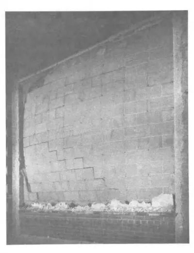
On the walls where half of the unexposed side was left bare, some
v e r t i c a l cracking was observed in the blocks after about 1 hour. Walls
until they collapsed at 117 and 130 minutes, respectively. Figure 8 shows the wall in the e a r l y stage of collapse and Figure 9 shows i t s condition a f t e r collapse. Note that the unexposed gypsum l a y e r was s t i l l in place and the wood f u r r i n g s t r i p s in reasonably good condition.
RESULTS F i r e T e s t s
The f i r e t e s t r e s u l t s a r e summarized in Table 11. F i g u r e s 10 to
15 show the significant t e m p e r a t u r e h i s t o r i e s and deflections. Hose Stream T e s t s
All walls, with the exception of Nos. 3 and 6, successfully withstood the hose s t r e a m t e s t . Because the collapse of Nos. 3 and 6 was unexpected, no alternate specimen had been prepared f o r a hose s t r e a m t e s t . These
walls, therefore, w e r e assigned ratings of only 1 hour r a t h e r than 1 1/2 hours. DISCUSSION
Although the f i r e t e s t s e r i e s was limited i n scope, the d a t a w e r e examined t o d e t e r m i n e i f a simple and reliable method could be found f o r calculating the contribution of gypsum wallboard to the f i r e endurance of masonry-wallboard a s s e m b l i e s . Two methods a r e proposed which appear to provide acceptable r e s u l t s .
The membrane method a s s u m e s that the additional protection provided by the wallboard i s a function p r i m a r i l y of i t s ability t o s t a y in place. Its contribution t o f i r e endurance, based on thickness, m a y be added d i r e c t l y t o that of the unprotected wall. Where wallboard is applied t o both s i d e s of a m a s o n r y wall, that on the unexposed s u r f a c e h a s been assigned t h r e e t i m e s the rating of that on the exposed s u r f a c e because it m a y be expected t o
remain in place for a significantly longer period. Table I11 shows the time assigned various thicknesses of wallboard by this method. Owing t o the collapse of both a s s e m b l i e s involving 4-in. hollow units in the test s e r i e s , the total allowable contribution of the wallboard on both the exposed and un- exposed s u r f a c e s should be limited t o a n increment equal t o the f i r e endurance value a s assigned in " F i r e P e r f o r m a n c e Ratings"
*
to the unprotected wall.It will be noted that the t i m e assigned t o wallboard m e m b r a n e s on the exposed surface corresponds t o that assigned by Supplement No. 2 t o s i m i l a r protective m e m b r a n e s when used in s t e e l or wood stud construction. For t h i s reason, the recommendations in Table I11 have been extended to include 5/8-in. standard gypsum wallboard.
-
:!: National Building Code of Canada, Supplement No. 2, F i r e P e r f o r m a n c e Ratings, ACNBC, 1965 (Note that f i r e performance ratings assigned depend on the type of aggregate in the units)
The p l a s t e r equivalent method d i f f e r s f r o m the m e m b r a n e method in that wallboard protection on t h e unexposed s u r f a c e i s a s s u m e d t o provide the s a m e protection a s gypsum p l a s t e r . Accordingly, i t s contribution t o the f i r e endurance of the composite a s s e m b l y m a y be calculated by t h e method
d e s c r i b e d in Table 1. 5. 1 of Supplement No. 2 for a s s e s s i n g t h e contribution
of p l a s t e r protection.
In t h i s method, the contribution of t h e wallboard on the exposed s u r f a c e i s calculated in a m a n n e r s i m i l a r t o that outlined in the m e m b r a n e method.
The limitation placed on t h e t o t a l contribution of the wallboard in t h e c a s e of 4-in. solid o r hollow walls a l s o applies in the c a s e of t h e p l a s t e r m e m b r a n e method.
The following examples show t h e calculations in computing the f i r e endurance of a 4-in. solid c o n c r e t e m a s o n r y wall having 1/2-in. gypsum wallboard on both s i d e s .
A) Membrane Method
-
Equivalent thickness of m a s o n r y units a sd e t e r m i n e d by m e a s u r e m e n t
-
F r o m Supplement No. 2, f i r e endurance ofunprotected wall
-
Contribution provided by 1/2-in. wallboardon both s i d e s (Table 111)
-
F i r e endurance of composite a s s e m b l y = 3. 60 in.=
57 rnin = 60 rnin=
117 rnin B) P l a s t e r Membrane Method-
Equivalent thickness of m a s o n r y units=
3. 60 in.-
Additional equivalent thickness provided by 1 /2-in.wallboard on unexposed s i d e = 1 . 5 x 1 /2 = 0. 75 in.
-
Total equivalent thickness = 4. 35 in.-
F r o m Supplement No. 2, f i r e endurancecontribution provided by 1 /2 -in
wallboard on exposed s i d e (Table 111)
-
F i r e endurance of composite a s s e m b l y=
8 2 rnin=
1 5 rnin=
97 rninAs t h e s e examples i l l u s t r a t e , t h e p l a s t e r equivalent method yields m o r e c o n s e r v a t i v e r e s u l t s than t h e m e m b r a n e method but m a y provide m o r e flexibility in dealing with v a r i o u s types of composite a s s e m b l i e s .
Table IV shows a c o m p a r i s o n of the r e s u l t s obtained by both methods in computing t h e composite f i r e endurance p e r i o d s of t h e a s s e m b l i e s t e s t e d in this p r o g r a m .
REG OMMENDATIONS AND CONCLUSIONS
Based on the limited amount of t e s t d a t a available, the proposed
methods appear t o provide a reasonably a c c u r a t e approach t o a s s e s s i n g
the contribution of wallboard t o the f i r e endurance of composite m a s o n r y
a s s e m b l i e s . In the absence of any specific t e s t d a t a o r when r e s o u r c e s
a r e not available t o p e r m i t a detailed analytical study, t h e s e methods m a y
be used t o provide acceptable e s t i m a t e s .
It should be noted that the method of attaching wallboard to m a s o n r y i s c r i t i c a l if the d e s i r e d performance in f i r e i s t o be achieved. Because little published information i s available on the ability of various attachment methods to e n s u r e adequate retention during f i r e exposure, it i s recommended that the methods employed in this t e s t s e r i e s constitute minimum acceptable
requirements, i. e.
,
the method of attachment shall be at l e a s t equivalent tothose described in this study. ACKNOWLEDGEMENT
The authors wish t o thank M e s s r s . E. 0. Porteous and J.
E.
BerndtGyp s u m B o a r d I 1 !" 3/8-in. r e g u l a r w a l l - I b o a r d e a c h s i d e
+-I---
2 -':1
1 /2-in. r e g u l a r w a l l - b o a r d e a c h s i d e I 3/8-in. r e g u l a r w a l l - b o a r d e a c h s i d e 1 /2 -in. r e g u l a r w a l l - b o a r d e a c h s i d e 4 - - - 3/8 -in. r e g u l a r w a l l - board e a c h s i d e Two 1/2-in. l a y e r s r e g u l a r w a l l b o a r d e a c h s i d e::: On unexposed f a c e wallboard w a s applied t o one-half of wall s u r f a c e only. T A B L E I
DESCRIPTION O F TEST SPECIMENS
Unit M a s o n r y Method of R e m a r k s
Wall Attachment
6 -in. hollow L a m i n a t e d Wallboard s e c u r e d with
u n i t s 3/4-in. c o n c r e t e n a i l s ,
a p p r o x . 1 n a i l p e r 2 s q ft
4-in. solid 2 - x i - x 0. 021 -in. S t e e l c h a n n e l s s p a c e d u n i t s s t e e l r e s i l i e n t a t 24 in. o. c . a t t a c h e d t o
channels m a s o n r y with 5-in. c o n c r e t 1 n a i l s a t 16 in. o. c . Wall- b o a r d s c r e w e d a t 8 t o 12 in. 0. C.
4-in. hollow L a m i n a t e d Wallboard s e c u r e d with
u n i t s 3/4-in. c o n c r e t e n a i l s , a p p r o x . 1 n a i l p e r 2 s q ft 6 -in. hollow u n i t s 4-in. s o l i d u n i t s 4-in. hollow u n i t s F i r s t l a y e r s c r e w e d , s e c o n d l a y e r l a m i n a t e d Filmst layer v e r t i c a l l y screwerl t o 2 4 - x 1 5/8-in. s t e e l s t u d s , second l a y e r h o r izontalIy l a i n i n a t e d . S t e c l stud s p a c i n g tvas 16 in.
I
0. C . L a m i n a t e d Nailed t o n o m i n a l 1-
x 3-in. wood s t r i p s Wallboard s e c u r e d with 3/4-in. c o n c r e t e n a i l s , a p p r o x . 1 n a i l p e r 2 s q f t Wood s t r i p p i n g s e c u r e d t o rnasonr y at 16 in. o. c. with 2-in, c o n c r e t e n a i l s . Wallboard secured t o s t r i p p i n g with I + - i n . l a t h nails.TABLE I1
SUMMARY O F FIRE TEST RESULTS
ma son r y w a l l without gypsum wallboard on either
(1) A l l e n , L. W., Fire Endurance of Selected Non-Load Bearing Concrete Masonry Walls, DBR F i r e Study No. 25
Ottawa, M a r c h 1070, (NRCC 11275)
(2) Small-scale t e s t m Ref. (1 1, with time reduced by 7'70 ( 3 ) Failed by collapse, no h o s e s t r e a m test
(4) Failed by c o l l a p s e , no hose stream t e s t
(5) Time f o r thermocouples under wall board to r e a c h 500°F
T A B L E
III
REC OMMENDED C ONTRIBUTION
TO
FIRE RESTSTANC E RATING O F G Y P S U M WALLBOARD FINISH ONMASONRY
A N D
CONCRETE( 1 ) F o r 4-in. walls of hollow m a s o n r y , t h e maximum allowable contribution of t h e wallboard is not t o exceed the value
assigned t o t h e unprotected wall itself (due t o the d a n g e r of c o l l a p s e ) Wallboard Thickness (in. ) 3 /8 1 / 2
5
/8 Total (1) 40 60 120 Contribution (Min) When Applied T o Exposed S u r f a c e Unexposed Surface 10 30 1 5 I 30 4 5 90I
I 1
I
-
PRESCRIBED TEMP EXPOSED WALLBOARD TEMP
MINUTES
FURNACE AND TEMPERATURE UNDER EXPOSED WALLBOARD
MINUTES UNEXPOSED BARE MINUTES UNEXPOSED COVERED MINUTES DEFLECTIONS
I I I I I 20 40 60 8i) 100 120
MINUTES
FURNACE AND TEMPERATURE UNDER EXPOSED WALLBOARD
MINUTES UNEXPOSED RARE I I I I I ( 20 A,] fin ao 1011 I 2.7, M l H U T f S UNEXPOSED COVEREP MINUTES LlFFLECTlONS
MINUTES
FURNACE AND TEMPERATURE UNDER EXPOSED WALLBOARD
MINUTES UNEXPOSED BARE MINUTES UNEXPOSED COVERED MINUTES DEFLECTIONS
I I -FURNACE TEMP
---
PRESCRIBED TEMP I rr IF; l4 I.? HOURStURNACE AND TEMPERATURE UNDER EXPOSED WALLBOARD
I HOURS UNEXPOSED SURFACE I 7 8 HOURS
UNEXPOSED SIDE UNDER GYPSUM BOARD
I I ! I I I I ! I
0 I ?
HOURS DEFLECTION
I I I
I A
FURYBSF TEMP
--- PRESCRIBED TEMP
----
EXPOSED WALLBOARD TEMPI
80 100 120
MINUTES
FURNACE AND TEMPERATURE UNDER EXPOSED WALLBOARD
MINUTES
UNEXPOSED SIDE UNDER GYPSUM 8omn
MINUTES
UNEXPOSED SURFACE
MINUTES
DEFLECTIONS
MINUTES
FURNACL AND TEMPERATURE UNDER EXPOSED WALLBOARD
MINUTES UNEXPOSED SURFACE
MINUTES
UNEXPOSED SIDE UNDER GYPSUM BOARD
MINUTES DEFLECTIONS