READ THESE TERMS AND CONDITIONS CAREFULLY BEFORE USING THIS WEBSITE. https://nrc-publications.canada.ca/eng/copyright
Vous avez des questions? Nous pouvons vous aider. Pour communiquer directement avec un auteur, consultez la première page de la revue dans laquelle son article a été publié afin de trouver ses coordonnées. Si vous n’arrivez pas à les repérer, communiquez avec nous à [email protected].
Questions? Contact the NRC Publications Archive team at
[email protected]. If you wish to email the authors directly, please see the first page of the publication for their contact information.
NRC Publications Archive
Archives des publications du CNRC
This publication could be one of several versions: author’s original, accepted manuscript or the publisher’s version. / La version de cette publication peut être l’une des suivantes : la version prépublication de l’auteur, la version acceptée du manuscrit ou la version de l’éditeur.
Access and use of this website and the material on it are subject to the Terms and Conditions set forth at
Moisture accumulation in walls due to air leakage
Wilson, A. G.; Garden, G. K.
https://publications-cnrc.canada.ca/fra/droits
L’accès à ce site Web et l’utilisation de son contenu sont assujettis aux conditions présentées dans le site LISEZ CES CONDITIONS ATTENTIVEMENT AVANT D’UTILISER CE SITE WEB.
NRC Publications Record / Notice d'Archives des publications de CNRC:
https://nrc-publications.canada.ca/eng/view/object/?id=aebbca87-8deb-4f03-9ca9-ba27712f9297
https://publications-cnrc.canada.ca/fra/voir/objet/?id=aebbca87-8deb-4f03-9ca9-ba27712f9297
rc,
N A T I O N A L R E S E A R C H C O U N C I LCANADA
CONSEIL NATIONAL DE RECHERCHES
:-;.,t
'5
1J-
-'7
TILL lN2rt2 i
n o . 2 2 1 ,
e . 2
BTDG
3{{w
MOISTURE ACCUMULATION IN W'ALI.S by
A . G . W i l s o n a n d G . K .
DUE TO AIR LEAKAGE
G a r d e n R I L E M / C I B S y m p o s i u m , H e l s i n k i , 1 9 6 5 I ' M o i s t u r e Problems in Buildingsrt PREPRINT 2 - 9 T e c h n i c a l P a p e r N o . 2 2 7 of the D i v i s i o n o f B u i l d i n g R e s e a r c h O T T A W A J u I y I 9 6 6
N R C 9 r 3 r
F r i c e 2 5 c e n t s37e-2786
T h i s p u b l i c a t i o n i s b e i n g d i s t r i b u t e d b y t h e D i v i s i o n o f B u i l d i n g R e s e a r c h o f t h e N a t i o n a l R e s e a r c h C o u n c i l . I t s h o u l d n o t b e r e p r o d u c e d i n w h o l e o r i n p a r t , w i t h o u t p e r r n i s -s i o n o f t h e o r i g i n a l p u b l i s h e r . T h e D i v i s i o n w o u l d b e g l a d t o b e o f a s s i s t a n c e i n o b t a i n i n g s u c h p e r r n i s s i o n . P u b l i c a t i o n s o f t h e D i v i s i o n o f B u i l d i n g R e s e a r c h r n a y b e o b t a i n e d b y r n a i l i n g t h e a p p r o p r i a t e r e r n i t t a n c e , ( a B a n k , E x p r e s s , o r P o s t O f f i c e N { o n e y O r d e r o r a c h e q u e r n a d e p a y -a b l e -a t p -a r i n O t t -a w -a , t o t h e R e c e i v e r G e n e r a l o f C a n a d a , c r e d i t N a t i o n a l R e s e a r c h C o u n c i l ) t o t h e N a t i o n a l R e s e a r c h C o u n c i l , O t t a w a . S t a r n p s a r e n o t a c c e p t a b l e . A c o u p o n s y s t e r n h a s b e e n i n t r o d u c e d t o r n a k e p a y -r n e n t s f o -r p u b l i c a t i o n s r e l a t i v e l y s i r n p l e . C c u p o n s a r e a v a i l -a b l e i n d e n o r n i n -a t i o n s o f 5 , Z 5 a n d 5 0 c e n t s , a n d r n a y b e o b -tained by rnz' These couPons rrra Council pu o f B t a i n r B u i l O t t a e a r c h
uuruililil
i|1ill]ilil
3
MUUUW
? {
2 - 9
MOISTURE ACCUMULATION IN WALLS DUE TO AIR LEAKAGE A . G . W I L S O N * ) a n d G . K . G A R D E N . . )
N a t i o n a l R e s e a r c h C o u n c i l ,
D i v i s i o n o f B u i l d i n g R e s e a r c h , O t t a w a C a n a d a
A number of cases of water and frost damage in masonry and non-loadbearing walls have been examined. Consideration of the weather conditions and the location and pattern of failure has shown that the quantities of water involved cou.ld not have resulted from vapour diffusion or rain penetration, and that condensation due to exfiltration of air was the ptimary source of moisture. Air exfilmates through the many cracks and joints comrrlon to all present methods of construction. In winter, the water vaPour contained by the air is cooled below its dewpoint temperature at some point in the wall and condensation occurs. The pattern and magnitude of building pressure differences inducing exfiltration and the concomitanr air and moisture transfer are discussed in this paper. some examples of related building failures are then described.
PRESSURE DIFFERENCES CAUSING AIR LEAKAGE
Pressure differences inducing air leakage in buildings are the result of one or more of the following: building chimney action; wind action; and imbalance of mechanical supply and exhaust air systems. As a first approximation, the pressure difference across the enclosure at any point can be taken as the algebraic sum of the pressure difference due to each source acting independently.
Pressue differences due to chimney action occur when the air inside and outside the building has a different specific weight resulting from differences in remperarure.
*) Head, Building Services Section, Division of Building Research, National Research Council, Ottawa, Canada.
") Construction Section, Division of Building Research, National Research Council, Ottawa, Canada.
2
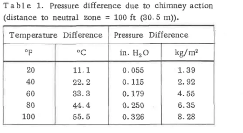
In temperate and cold climates, this effect is greatest during the winter. Under ttre influence of chimney action,alone, air flows into the building through openiags at lower levels, flows upwards in the building and out at higher levels. Somewhere between, there is a level at which no in- or out-flow occurs, sometimes referred to as the neufial zone, where the pressure inside equals that outside. Tbe ttreoreti-cal pressure differeflce across the enclosure at any 1evel is equivalent to the difference in weight per unit area of inside and oueide columns of air between the level and the neutral zone. Table I indicates the magnitude of these pressure differences.
Table 1. Pressure difference due to chimney action (distance to neutral zone = 100 ft (30. 5 m)).
Temperature Difference Pressure Difference
O F i n . H r O kg/mz 2 0 A A 6 0 8 0 1 0 0 1 1 . L o r o 3 3 . 3 44.4 5 5 . 5 0 . 0 5 5 0 . 1 1 5 0. 1,79 0. 250 0 . 3 2 6 1 . 3 9 2 . 9 2 4 . 5 5 6 . 3 5 8 . 2 8
The neutral zone level for a building depends upon the vertical distribution of cracks and openings in the enclosure; published data are few. Measurements across entrances of tall office buildings by Vin [f] indicate an apparenr level of the neutral zone of ?0 per cent of the building height for conventional construction and 30 per cent of the height for a very tight modem building. In recent ,meas-urements. by the Division of Building Research on a new 9-storey office building, with masonry curtain walls and alternate sealed and openable windows, a level of 56 per cent of the building height was established with all mechanical supply and exhaust systems shut down and sealed. The pressure difference at any level was reduced to approximatety 80 per cent of theoretical values due to resistance to vertical flow wirhin the building. Vertical air flow occurs via elevator and various service shafts and stairwells. Recorded experience indicates that sealing against vertical flow is usually quite imperfect in buildings as normally consrructed. If pe.rfect sealing at each floor were possible, the effective chimney height would be limited to the distance between floors.
It shor:ld also be recognized that chimney action can occur between the air in the building and colder vertical air spaces in the building envelope wheu openings exist at two or more levels. For exarnple, significant air interchange can take place between the space of a double window and the inside of the building [2];
2 - 9
similar flow occurs in furred pipe spaces in the outer walls which are often open to heating or air conditioning units at floor level and to spaces above suspended ceilings. Air flow can then occur from the room into the wall space at upper levels and out to the roorl at lower levels.
It is not urlcomfiron in Canada for engineers to design and operate mechanical ventilation systems to provide an excess of air supply over exhaust in order to pressurize the building. Generally, the purpose of pressurization is to reduce in-filtration at doorc and windows to improve comfort and inhibit rhe entry of air pollutants; sometiines it rnay be inadvertent. The effect on pressue differences across the enclosure will depend upon the air tightness of the building and the amount by which supply air exceeds exhaust. Little, if any, published information obtained by test is available on the air tightness of large buildings. In measurement by DBR on the 9-storey building referred to previously, pressurization of the building as norraally operated varied from 0. 01 to 0. 09 in. (0.25 to 2.3 mm) of water. With the exhaust system shut down, and the supply system providing outside air equivalent to about 3.2 aft changes per hour, rthe building pressure was about 0.18 in. (4. 6 mm) of water higher than outside. Measurements on a very high uretal curtain wall building with sealed' windows indicate that pressurization up to 0.5 in. (L2. ? mm) of water may occur with normal system operation, and that higher values can be induced. Very substantial presstue differences due to mechanical ventilation systems are thus possible. When superimposed on normalchimney action, with excess supply air introduced uniformly at all floors, the effect is to reduce the pressure difference at the bottom of the building approximately by the amount of pressurization and to increase the pressure difference at the top by a similar amount. The neutral znne level is lowered correspondingly. Infiltration is thus reduced at lower levels and exfiltration increased_at upper ones.
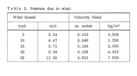
Infiltration of air due to wind on the windward sides of buildings is widely recognized. At the satne tiine, wind action produces negative pressures and a potential for exfiltration on leeward sides. Negafive pressures can also occur at the top of walls in the vicinity of parapets and along the corners, even on wind-ward sides. Wind pressures around buildings are usually expressed in terms of the wind velocity head. Positive pressures generally vary from 0.4 to 0. 9 of the velocity head; negative pressures are usually a smaller fraction, but can have values greater than unity. The pressure inside a building under wind action depends upon the external pressure pattern and the distribution of openings in the enclosure. Measured values of pressure difference across the leeward walls of the aforernentioned 9-storey building at the vertical centreline, expressed as a fraction of the veloci,ty head of the wind above the building, were as high as 0.35 at rhe top and 0.25 at the bottom. lt will thus be seen froryr Table II that wind action can produce a signifi-cant potential for air exfiltration.
Table 2. Pressure due to wind.
Wind Speed Velocity Head
mph m/s in. water kg/mz 1 0 15 20 o < 2 . 2 4 4 . 4 7 6 . 7 t 8 . 9 4 1 1 . 2 0 0 . 0 1 2 0. 048 0. 104 0. 193 0 . 3 0 1 0 . 3 0 4 I . 2 2 0 2 . 5 9 0 4 . 9 1 0 7 . 6 2 0
AMOUNT OF CONDENSATION DUE TO AIR LEAKAGE
The extent of condensation due to air leakage depends on the quantity of air flow, its initial moisture content, and the reduction in temperature that it under-goes in passing through the building envelope. The volume of air 'exfiltration depends on the air pressure differences, the time over which they prevail, and the leakage characteristics of the construction. These will vary with the building and climate. In general, moisture problems due to exfiltration will increase with increasing building height, decreasing average winter temperatrue, and increasing building humidity.
Published information on leakage characteristics of conitruction, other than windows, is not extensive. To illustrate the pote$tial for condensation in walls due to air leakage, consider a t2-in. (30 cm) thick unplastered brick wall with no inside finish. Masonry is commonly left unplastered between suspended ceilings and the floor above, and behind recessed heaters or air conditioning units under windows. The air leakage through each L00sq ft 19.3sqm) of wall can be taken asequiva-lent to that through a sharp-edged orifice having an area of 3. L sq in. (20 sq cm)
[e]. t" represent the cumulative effect of a winter season on rloisture nansfer through upper walls in humidified multi-storey buildings, it is not unrealistic to assume, for colder Canadian climates, that the following avenge conditions prevail for L00 days: inside temperature and relative humidity of 73oF (23"C) and 30 per cent relative humidity; outside temperature of 15"F (-9"C); pressue difference inducing exfiltration of 0.15 in. of water (3.8 kg/rn2), equivalent to a distanceof about 80 ft (24 m) frorn the reutral zone.
The heat and moisture exchange between the flowing air and masoffiy will be complex. If it is assumed that the air leaves the cold side of the wall saturated at outside teinperatrue the total moisture deposited in the masonry in 100 days is 735 lb per 100 sq ft 136 kg/rnz). It is of interest for comparison to approximate the amount of moisture that might be deposited by vapour diffusion; again the real situation is most complex but simplification is appropriate for present Purposes'
2 - 9
Taking as the potential for moisture deposition the difference between the room vapour pressure and saturation vapour pressure at outside temperatue, and taking ao average permeance value for the brick of 1 perm (2.02 x 10⁻⁶ kg/mzh pr. kg/mz), the moisture deposited is 4.5lb per 1o0 sqft 10.zzkg/mz). Air leakagethus presentr a significant potential for moisture deposition that can be two or more orders higher than that due to diffusion. Furthermore, moisture deposition due to air leakage may be concentrated in the viciniry of the cracks through which air flow occuts. FIELD OBSERVATIONS
Many cracks and openings, through which air can exfiltrate, exist or develop in modem buildings, and resulting moisture damages take many forms. A few examples are given in the following section.
Disruption of masonry (Figure 1) occurred during the fust winter after occuparicy, at the top of the walls of a masonry-clad, steel-frame, humidified building. With the aid of smoke, it was determined that air was leaking outwards tluough the unplastered poftions of the masonry walls (e. g. above suspended ceilings) and through cracks between structural elements and the masonry. Moisture accumulations (due to condensation) were found to be concentrated adjacent to air leakage paths. Further examination showed that the same prohlem occurred below window sills (Figure 2). Figure 3 indicates the construction, and pattef,ns of air leakage and condensation at the window sills. The moisture and thermal conditions in both these cases were conducive to the growth of ice tenses [+] in the mortar joints, which caused the disruption of the masonry and lifting of window sills. Other
Figure 1. Disruption of masonry by frost action in wet materials.
Figure 2. Damage to rnassrrryr at window sills as a result of excess rrpistuse from condensation associated with air leakage.
Figure 3. Diagram of window sill showing air leak-age\paths and location of condensadon.
areas on the building subjected fo suction from the prevailing wind also showed indications of moisture accumulation.
In this building, air exfiltration through the spaces between double windows produced excessive condensation on the inner surface of the outside pane of glass. The pa.ttern of air pressure differentials was easily seen as the windows at the seventh (or top) floor of the building had a great accumulation of frost while those at the bottom remained relativelv clear.
2 - 9 '
During cold ryeather, there was continual dripping of water from wall drain holes at window heads of a high-rise mefal and glass curtain wall building. The formation of icicles the size of a man's arm at window heads some 400 ft above the street carsed considerable alarrn. The design of this curtain wall followed the commor practice of endeavouring to seal the outside surface of the wall against rain peneEation; it was assumed that this would also provide adequate air tightness, Recognizing, however, that any wall designed on this basis did eventually leak in rain storms, the spaces within the wall were designed to lead the water to the exterior through drain holes in the window heads, No attempt was made to provide a seal against air flow at interior surfaces so that cracks and openings leading to window mullion and wall spaces occurred regularly throughout tire height of ttre building. Air interchange between the building interior and these cold spaces produced condensation with constant dripping of water from window heads and soiling of the windows throughout the winter. At floors above the neutral zone, air exfil-tration through the exterior drain holes increased the rate of moisture accumulation and the severity of the problem .at higher levels. Because the building was highly pressurized, air exfflnation occurred ov€r rilost of its height. Condensation, stored as frost, melted when the outdoor tempsrature rse to about 25oF (-4'C) aftet a prolonged cold spell. Frorn ttre 36 ft (11 m) of wall enclming mechanical rooms at the top of the building, r,rater flowed out the drain holes at the top row of windows and formed large icicles.Staining and stone"di*placement occuned in a building {Figure 4) due to moisturc accumulation in the colilnn cladding. The building was not intentionally humidifiei but the walls were retratively airtight and the nrpchanical system was inoperative, so that moisture added to the air by breathing, floor washing, and melting of snow from footwear caused a moderate increase in humidity. The humidity level was not constant nor was it sufficient to produce objectionable condensation on the double glazing or metal window frames.
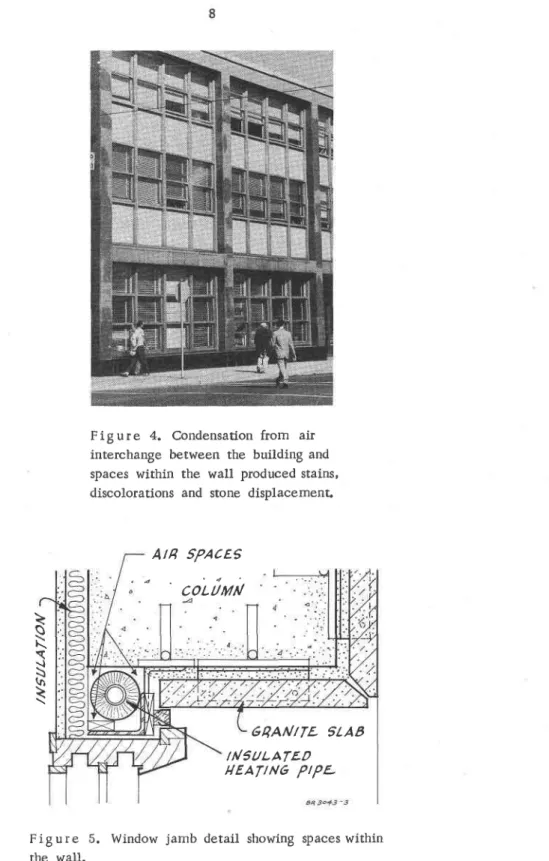
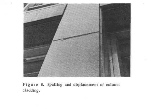
The window jamb detail in Figure 5 shows that the insulated mechanical lines were concealed in wall spaces outside the building insulation. Above the suspended ceiling, the wall finish was omitted and near the floor, the run-outs serving the bank of heating convectors passed through the wall finish. Air interchange between the building and the pipe spaces due to chimney action resulted in condensation on cold surfaces whenever the humidity was high enough. Since it accumulated as frost, suscained conditions for condensation were not necessary to provide a large quantity of water. Upon thawing, most of it was absorbed by the backup mortar. Refreezing of the water in the mortar produced ice lenses that displaced the column cladding stones (Figure 6). Once the cladding was displaced, air exfiltration increased and contributed to the rroisture accumulation, as did rain penetration at certain times of the year.
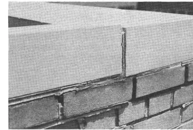
Figure 4. Condensation from air interchange between the building and spaces within the wall produced stains, discolorations and stone displacemenL
Figure 5. Window jamb detail showing spaces within the wall.
AtB SPACES
" ' co'tiui
\
v\
\
s
(rt\
64AN/TL SLAB
/NSULATEO HEAT|NG P|PL2 - 9
Figure 6. Spalling and displacement of column cladding.
CONCLUSION
Air exfiluation through walls and air interchange between exterior wall spaces and a building in winter are a principal source of water leading to damages due to wetting and frost action in both old and new buildings. Good wall design requires adequate restriction to both types of air movement, not only in the building as originally constxucted but throughout its intended life.
This paper is a contribution from the Division of Building Research, National Research Council of Canada and is published with the approval of the Director of the Division.
1 0
1 .
2 .
REFERENCES
M i n , T. C. , Winter infiltration through swinging-door entrances in multi-story buildings. Transactions, ASHME, Vol. 64, 1958, p, 421.
W i l s o n , A . G . a n d N o w a k , E . S . , C o n d e n s a t i o n b e t w e e n t h e p a n e s o f d o u b l e windows. Transactions, ASHME, Vol. 65, 1959, p. 551.
3. ASHME Guide and data book, FundamentaLs and equipment, 1963, p. 434. 4. Garden, G.K., Damage to masonry constructions by the ice-lensing
mech-anism. Paper to be presented at the RILEM/CIB loint Symposium on "Moisture Problems in Buildings", to be held in Helsinki, 16-19 August 1965.