Publisher’s version / Version de l'éditeur:
Vous avez des questions? Nous pouvons vous aider. Pour communiquer directement avec un auteur, consultez la première page de la revue dans laquelle son article a été publié afin de trouver ses coordonnées. Si vous n’arrivez pas à les repérer, communiquez avec nous à [email protected].
Questions? Contact the NRC Publications Archive team at
[email protected]. If you wish to email the authors directly, please see the first page of the publication for their contact information.
https://publications-cnrc.canada.ca/fra/droits
L’accès à ce site Web et l’utilisation de son contenu sont assujettis aux conditions présentées dans le site
LISEZ CES CONDITIONS ATTENTIVEMENT AVANT D’UTILISER CE SITE WEB.
Technical Translation (National Research Council of Canada), 1969
READ THESE TERMS AND CONDITIONS CAREFULLY BEFORE USING THIS WEBSITE.
https://nrc-publications.canada.ca/eng/copyright
NRC Publications Archive Record / Notice des Archives des publications du CNRC :
https://nrc-publications.canada.ca/eng/view/object/?id=14d51ca2-bade-40d0-a9e9-0bb7de42437b https://publications-cnrc.canada.ca/fra/voir/objet/?id=14d51ca2-bade-40d0-a9e9-0bb7de42437b
Archives des publications du CNRC
For the publisher’s version, please access the DOI link below./ Pour consulter la version de l’éditeur, utilisez le lien DOI ci-dessous.
https://doi.org/10.4224/20386669
Access and use of this website and the material on it are subject to the Terms and Conditions set forth at
Methods of determining creep, long-term strength and compressibility
characteristics of frozen soils
Vyalov, S. S.; Gorodetskii, S. E.; Ermakov, V. F.; Zatsarnaya, A. G.;
Pekarskaya, N. K.; National Research Council of Canada. Division of
Building Research
NATIONAL RESEARCH COUNCIL OF CANADA
TECHNICAL TRANSLATION 1364
METHODS OF DETERMINING CREEP, LONG - TERM STRENGTH
AND COMPRESSIBILITY CHARACTERISTICS OF FROZEN SOILS
BY
S. S. VYALOV ET AL.
STATE COMMITTEE OF THE COUNCIL OF MINISTERS CU. S.
s.
R) FOR CONSTRUCTIONPUBLISHER
NAUKA. MOSCOW, 1966
TRANSLATED BY
H.
R.
HAYES AND V. POPPETHIS IS THE ONE HUNDRED AND EIGHTIETH OF THE SERIES OF TRANSLATIONS
PREPARED FOR THE DIVISION OF BUILDING RESEARCH
OTTAWA 1969
The study of frozen ground mechanics and its application in engineering practice has been more widely developed in the Soviet Union than elsewhere. Prominent among literature in this field are compilations or manuals describing laboratory or field procedures to be carried out prior to engineering construction.
The work translated here describes laboratory procedures for testing of strength and deformation properties of frozen soil to be carried out in connection with foundation design. The editor Dr. S.S. Vyalov, who is also one of the contribu-tors, is one of the leading Soviet scientists in this field. The translation has been undertaken because of the growing interest in North America in construction procedures on frozen ground.
The Division wishes to record its thanks to Mr. H.R. Hayes and Mr. V. Poppe, Tl'anslations Section, National Research Council, for translating this paper, to Mr. P.J. Williams of this
Division and Dr. H.B. Poorooshasb, University of Waterloo, who checked the translation.
Ottawa June, 1969
R.F. Legget Director
Title:
Authors:
Publisher:
Technical Translation
1364
Methods of determining creep, long-term strength and compressi-bility characteristics of frozen soils
(Metodika opredeleniya kharakteristik polzuchesti, dlitel'noi prochnosti i szhimaemosti merzlykh gruntov)
S.S. Vyalov, S.E. Gorodetskii, V.F. Ermakov, A.G. Zatsarnaya and N.K. Pekarskaya
Research Institute of Foundations and Underground Structures, Academy of Science U.S.S.R., State Committee of the Council of Ministers (U.S.S.R.) for Construction
(Nauchno-Issledovatel'skii Institut Osnovanii i Podzemnykh Sooruzhenii, Akademiya Nauk SSSR, Gosstroi SSSR)
Nauka, Moscow,
1966
Translators: H.R. Hayes and V. Poppe, Translations Section, National Science Library
frozen soils. The authors examine the fundamentals of frozen soil rheology, methods of testing frozen soils for long-term strength, creep and compressibility, also practical methods of processing test data and definitions of propprties required in the calculation of frozen soils in terms of lirniting states.
This book is intended for workers in industrial and scientific research laboratories engaged in the study of the mechanical pro-perties of frozen soils.
General Editor
Professor
S.S.
Vyalov, D.Sc. (Eng.)Foreward. . . 4
I. General mechanism of frozen soil deformation. 8 Rheological processes in frozen ground... 8
Deformation pat terns. . . 10
Compressibility of frozen soils.. 15
Long-term strength... . . 18
II. General requirements for tests. 23 Preparation of specimens ; . . . 23
Instrument and test condition requirements. '" 24 III. Methods of creep and long-term strength testing with uniaxial compression , .. .. 26
Instruments. . . 26
Rapid load action t e s t s . . . 27
Long-term load action t e s t s . . . 29
Processing experimental data and determining creep characteristics. . . 33
Determining long-term strength characteristics... 40
Simplified method of determining creep characteristics... 42
Processing experimental data and determining creep 1 characteristics of long-term strength... . . . 44
IV. Methods for long-term strength testing at shear under creep condi tions. . . 46
Ins trumentation. . . 46
Tests at rapid load a c t i o n . . .
47
Tests at long-term load action...
49
Processing experimental data and determining characteristics of long-term strength. 52 V. Methods for compression testing. 55 Instrumentation " 55 Testing p r o c e d u r e . . .
56
Processing experimental data and determining compression characteristics. . . 60
VI. Simplified method for creep and long-term strength testing with the aid of a dynamometric device : . . . .
65
Description of the m e t h o d . . .
65
Instrumentation. . . 69
Experimental methods... . . . 72
Processing experimental data and determining characteristics of creep and long-term s t r e n g t h . . . 75
Appendices. . . 82
References '" , '" .. 93
METHODS OF DETERMINING CREEP, LONG-TERM STRENGTH
AND COMPRESSIBILITY CHARACTERISTICS OF FROZEN SOILS
Foreword
Frozen soils, because of the presence in them of ice and unfrozen water, possess clearly defined rheological* properties - the capacity to develop imperceptibly slow deformations (creep) and to lose strength during prolonged load action. Volumetric consolidation deformations also develop in plastic-frozen soils. These characteristics must be taken into account when
studying the mechanical properties of frozen soils and in evaluating frozen soils to be used as building foundations, media in which buildings are erected, and construction material.
Frozen soils should be evaluated in terms of two limiting states -strength and deformation.
The evaluation of frozen soils for strength (bearing capacity) consists in determining the load at which, during a given period of time (the useful life of the bUilding), a state of limiting equilibrium occurs in the soil; this is the ultimate load, and if it is exceeded the soil fails or loses its strength. The methods of the limiting equilibrium theory (the theory of plasticity) are used for the calculations, while allowing for the varia-bility of strength characteristics in time. Methods of calculating the bearing capacity of frozen soils used for building foundations have already been dealt with in published literature(1,2), as also have methods of eva-luating frozen soils used as protective enclosures in sinking excavations by the artificial freezing method(3).
When evaluating frozen soils for deformations, the load calculated is that at which deformation during a given period reaches the maximum permiss-ible for the structure. Calculations are made by methods employed in the creep theory, for which it is necessary to know the deformation growth pattern and the deformation characteristics of the frozen soil.
Methods of calculating for deformations in protective enclosures of frozen soils are given in reference
3.
Methods of evaluating frozen soil foundations for deformation are not yet sufficiently well established and for this reason they are at present restricted to the calculation of ultimately stabilized settlements. For these calculations the method generally accepted in soil mechanics is used, but allowing for the variability of the compressibility characteristics in relation to load and soil temperature, which vary with depth(l). The bearing * Rheology - the science of the deformation and flow of solids.
capacity (strength) of the foundations of industrial and civic buildings composed of hard-frozen soils are evaluated on the basis of long-term strength characteristics.
All the above calculations pertain to those cases in which it is inten-ded to maintain the soils used for building foundations, media or material in a frozen state. In addition it is necessary to take into consideration the temperature regime of the frozen soils, since their mechanical properties depend largely on this factor. In view of the complexity of solving problems of strength and creep at a temperature that varies in space and time (which is usually the case in actual conditions), it is permissible to employ approximation methods: computing the effect of temperature change in time by introducing into the calculation the dependence of the deformability and strength characteristics on the temperature of the frozen soil, and computing the effect of temperature change in space by dividing the given frozen mass into a series of zones with averaged temperature values, i.e. reduce the problem to evaluating a mass with non-uniform characteristics. In order to make these calculations, it is necessary to know: for deformation calcula-tions, the relation between stress and deformation and the pattern of deve-lopment in time, as well as the compressibility characteristics; and for strength calculations, the strength characteristics (at compression and shear) and their variation in time. Determination of all these character-istics must take into account their relationship to the temperature of the frozen soil.
The aim of the present work is to standardize the methods of determining the characteristics of long-term strength, creep and compressibility under laboratory conditions.
In the first section, which is of a general nature, the basic patterns of creep and long-term strength of frozen soils are examined.
These patterns were revealed as a result of earlier research. The research data and validation of the patterns have been dealt with in publi-shed works(l-lO). These works also provide a more detailed background to questions relating to the theory of frozen soil rheology and its practical application.
The main sections of the present work are devoted to the testing of frozen soils for long-term strength, creep and compressibility, to practical methods of processing experimental data and to the determination of
calcu-lated characteristics.
The rheological patterns and the methods of establishing them set forth in this work are also valid in principle for non-frozen clay soils.
The procedures were worked out on the basis of research conducted by the former V.A. Obruchev Permafrost Institute, Permafrost Department of the Moscow State University, and the Permafrost Institute, Siberian Division
of the Academy of Sciences U.S.S.R.
The ideal method of determining the strength and deformability charac-teristics of frozen soils is to test for creep in the presence of a complex stress state, e.g. triaxial compression, or distortion and compression, which permits the invariant relation between all the stress and deformation components and time to be determined. However, these methods and the
necessary apparatus are still in the 、・カ・セッーュ・ョエ。ャ stage. Therefore, in the present work we shall examine test procedures for the simplest forms of stress state, employing standard equipment for testing thawed soils and
rock. The instruments are modified slightly for testing frozen soils. Here, of course, we shall have to contend with the well-known defects of these instruments, partiCUlarly of the instruments used for shear tests.
The proposed ャッョセMエ・イュ strength and creep test procedures apply to uniaxial compressions and shear tests. The first of these provides the basis for ・ウエ。「ャゥウィゥョセ the characteristics and pattern of deformability used for evaluating frozen soils with respect to deformation (creep) and for determining the characteristics of long-term strength at compression, which may be used for evaluating the strength of frozen clay soils (which do not p o s s e s s "internal friction"). Shear tests enable us to determine the cohesive forces which vary in time and the "internal friction", both of which are needed to calculate the strength (bearing capacity) of frozen sandy, sandy silt and silty clay soils.
Special attention is given to a simplified method of testing by means of a dynamometric instrument. Since this instrument is new, a diagram, description and brief summary of the theoretical principles of the method
are セゥカ・ョ in the text.
Another simplified method of determining the characteristics of
long-term ウエイ・ョセエィ which can be recommended is N.A. Tsytovich's method of testing
by ball stamp depression. The relevant test procedures are given detailed treatment in the cited works(1,2,7,lO,11).
A special section of this work is devoted to compressibility tests of frozen soils. It is necessary to conduct these tests in order to detErmine the compressibility characteristics used in calculating the ultimate settle-ment of the foundations of buildings erected on frozen plastic soils.
The selection of the form of testing is governed by evaluation require-ments. Here we should take into consideration the fact that the calculations and tests set forth in this work are not intended to meet quantity or bulk requirements, but are for use in the planning of particularly important structures and structures for which no frozen soil parameters have been given in standard specifications. Finally, the indicated tests may be applied in the investigation of the mechanical properties of frozen soils
for research purposes.
This booklet was compiled at the Permafrost Laboratory, Research Institute of Foundation Soils and Underground Structures (formerly the V.A. Obruchev Institute of Permafrost Studies) by a group of authors:
S.S. Vyalov (Section I), N.K. Pekarskaya (Sections II and IV), S.E. Gorodet-skii (Section III), A.G. Zatsarnaya (Section V), S.S. Vyalov and V.F. Erma-kov (Section VI) with the cooperation of E.P. Shusherina (Moscow State University). The work was carried out under the guidance of Professor S.S. Vyalov, D.Sc. (Eng.).
Observations and wishes expressed by organizations and individual specialists have been taken into consideration in the compilation of the text. To these the authors convey their sincere gratitude.
I. GENERAL MECHANISM OF FROZEN SOIL DEFORMATION
Rheological Processes in Frozen Ground
Stresses are divided into normal cr, which act perpendicularly to a
セゥカ・ョ section, and tangential (shear) T, which act parallel to the section. Deformations are measured in relative units and are divided into relative linear (relative elongations) E and relative angular (relative shears) y.
The relationships examined below are written to conform with components cr and E, but they remain valid also for components T and y with the appropriate changes in the values of the parameters in the formulae.
Deformations are either elastic, which recover when the load has been removed (reversible), or plastic, which do not recover when the load has been removed (non-reversible).
Depending on the nature of the relationship between stress and defor-mation, distinction is made between linear deformations, which are directly proportional to the stress, and non-linear deformations related to the stress in other ways.
Depending on the rate of development of the deformation process, defor-mations are regarded as either instantaneous, which occur at the speed of sound, or deformations which develop over a period of time, i.e. viscous. Instantaneous and slow deformations may be partly reversible (elastic) and partly non-reversible (plastic) and may be linear or non-linear.
A reversible deformation which develops over a period of time is called a visco-elastic or elastic reaction deformation; i t recovers over a period of time (reversible elastic reaction). A residual plastic deformation which develops over a period of time is sometimes called a plastic reaction.
Variations in the stress-deformation state of a body in time are called rheological processes. These processes are manifested in the following
forms:
creep, i.e. the development of a deformation over a period of time, even when the stress is unchanged (continuing viscosity);
relaxation, i.e. diminution (weakening) of stress required to maintain constant deformation;
loss of strength, i.e. decrease of that stress level which causes failure of the body with an increase in the time of bad action.
The creep process may be represented in the form of a graph. For this, time t is plotted on the graph along the axis of the abscissae, and the relative deformation E caused by the action of a continuing stress cr, along the axis of the coordinates. Usually, a series of creep curves is construc-ted, for which tests are carried out on a series of specimens of one type to which different stresses (constant for a given specimen) are applied.
Foreach stress there is a corresponding creep curve (Fig. 1).
Deformation of frozen soil is made up of an initial conditionally instantaneous (E
i n i t) deformation (Fig. 2a, section OA) which occurs imme-diately after the application of a load, and a deformation which develops over a period of time E(t) (sections AB and AD)
E = E
i n i t + E(t).
(1)
The process of development of slow deformations includes:
the first stage of creep, or the stage of attenuating (irregular) creep (Eat) with decreasing rates of de f'o r-m.t t.Lon (Fig. 2a, section AB);
the second stage of creep, or the stage of visco-plastic flow (steady state creep) E
f at a more or less steady rate of deformation (section BC); the third stage of creep, or the stage of progressive flow E at an
pr ever-increasing rate (section CD)*. In tensile stress and ;,hear tests
(when the area of the specimen decreases) this stage always ends in "brittle" failure for compact frozen soils with a low moisture content or "viscous" failure (which is accompanied by substantial plastic deformations) for heavily ice-impregnated, plastic frozen soils. In compression tests (when the area of the specimen increases) this stage ends in "brittle" failure for soils of the first type, or in the complete flattening of the sample, without visibly disturbing its wholeness, for soils of the second type.
The process, which includes all the above-mentioned stages, is called the process of non-attenuating creep; it develops under fairly large stresses. At low stress levels the second and third stages of deformation are
practically non-existant, and in this case the entire process is callea attenuating creep (Fig. 2b). This process takes place at an ever-decreasing rate of deformation, which either reaches the ultimate, (virtually) stable value E
u l t ' or develops unrestrictedly, but at a decelerating rate, tending to zero ("long-lasting creep").
Partial recovery of the deformation takes place when the load is removed from the specimen at any moment of time (Fig. 3).
An initial virtually instantaneous deformation E
i n i t (Fig. 3a, section 0-2) recovers immediately on removal of the load (section 3-4), and in this case the recovery of this deformation may be either full or partial, depen-ding on the magnitude of the load. In the first case, the entire initial deformation is elastic (E
i n i t
=
Eel) and, correspondingly, the initial sec-tor 0-2 of the loading curve is equal to section 3-4 of the unloading curve.* Editor's note: The length E is apparently erroneously indicated in the pr
In the second case, the initial deformation computed from the elastic Eel (section 0-1) and the plastic Ep l (section 1-2) parts: Ei n i t
=
eel+
Ep l' in which case only Eel (section 3-4 equals section 0-1) recovers.The initial deformation is called substantially instantaneous because in practice the loading does not occur "instantaneously", i.e. at the speed of sound, but occupies a certain length of time.
An attenuating (irreGular) creep deformation recovers over a period of time only partially (section 4-5 of the curve), i.e. consists of a defor-mation of elastic reaction £el(t) (section 5-6) and of plastic reaction
Epl(t) (segment
5-7).
A deformation with a steady plastic-viscous flow, like one with a pro-gressive flow, is absolutely irreversible.
The total deformation of creep E at any instant of time t consists of the recovering, i.e. elastic Eel(t) and the residual, i.e. plastic £(t) parts (Fig. 3b).
( 2 ) These forms of deformation are separated in the event that it is necessary to study the elastic properties of the soil (for example, in calculating the short-term effect of loads, and of unloading) and are determined on the basis of unloading tests.
Deformation Patterns
The main characteristic of the deformative properties of frozen soil is the relationship between the stress
a
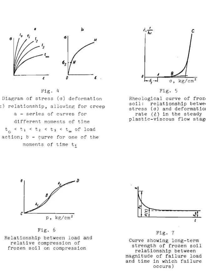
and the total deformation £ (which includes the elastic and plastic parts).The relationship between stress and deformation in conditions where creep is encountered is determined with regard to the period during which the load is applied, since for each time t value the magnitude of this deformation (at one and the same stress) will be different and constantly increasing. Similarly, in the stress-deformation diagram a series of curves is obtained, each of which characterizes the relationship between stress and deformation at a given moment of time t (Fig. 4).
Curve to corresponds to the initial (substantially instantaneous) defor-mations, curve too corresponds to the ultimate, stabilized deformations and is obtained from long-term tests leading to the stabilization of the defor-mations. The intermediate curves correspond to different instants of the time of load action. Curves for different t values mayor may not be similar.
The nature of the stress 0 - total deformations E curves for any given moment of time t depends on the type of soil (Fig. 4b). Usually these curves
consist of two sections, the boundary of which is the point of gradient change N (0). Each section of the curve conforms to definite patterns. The section
ON
(where 0 < as) may be linear, deformation being directly proportional to the stress, or non-linear; in the sectionNM
(where a > 0 )s the stress usually depends on strain in a non-linear manner.
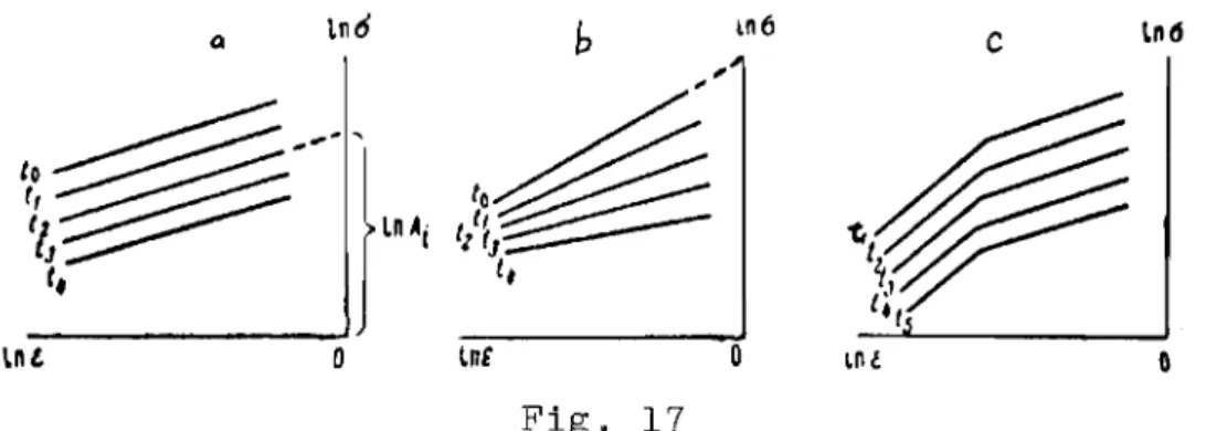
In order to simplify the calculations, i t is sufficient for practical purposes to assume that the stress-deformation curve for different instants of time t are mutually similar and that each of them is described by a
single non-linear relationship. Usually an exponential relationship is assumed and then the interdependence of stress and deformation at any moment of time t will be expressed by the following equation (which is verified by experimental data):
m
a
= A (t)E: ,where A(t) - deformation coefficient, kg/cm2;
m<l - hardening coefficient (dimensionless value).
Coefficients A(t) and m are determined experimentally as parameters of the curves shown in Figure 4. Coefficient m depends to a negligible degree on soil temperature and time of load action, and may be taken as constant for a given soil.
Coefficient A(t) depends on the composition of the soil, its temperature and the time of load action. With accelerated loading, coefficinet A has a maximum value A =
A
i n i t and is the coefficient of initial deformation, i.e. corresponds to curve t shown in Figure 4a. With an unlimited, long-term
o
load action coefficient A has a minimum value A = Am, being the coefficient of the ultimate stabilized deformations when the creep process acquires an attenuating character, or tends to zero if the process is of a non-attenua-ting character.
o Coefficient A may be expressed by the modulus of deformation E
=
E having the relationship( I - m m I-m
A(t) = E t)E = E (t)a ,
where E(t) is a quantity which varies in time.
If the parameter m has a value close to unity, coefficient E(t) assumes the significance of a linear modulus of deformation
A(t) = E(t).
The value of coefficient A(t) may be used in deformation calculations when calculating for some moment of time t. In this case the value of A(t) corresponding to the moment of time, determined directly from the stress deformation graph, is substituted in the calculation. Where i t is necessary to determine the development of deformations over a period of time i t is
necessary to know the deformation rates.
The pattern of change in time t of deformation £ caused by stress 0
which varies in time, may be determined from the equation: m
£ = o(t) +
S
o(v)K(t-v)dv.
Ai n i t 0
( 4 )
in cm2 / k g (force)'hr is the function of creep m
E
At a constant load (0 const) the expression takes the following form t
A 0 + 0 セ K(t)dt,
init 0
where A
i n i t is the initial deformation coefficient in kg(force)/cm
2 ;
m is the hardening coefficient (m<l);
v
is a variable of integration; K(t) _ 1 deEm)- 0
dtwhich characterizes the change in the rate of deformation in time. This function is related to the time variable coefficient of deformation A(t) in
( 6 )
equation (3) in the following way:
K(t)
=
セヲ gHセj
Thus it is sufficient to determine experimentally either K(t) or A(t). The first terms in equations
(4)
and(5)
describe initial deformation, and the second terms, the deformation which develops in time. If the initial deformation is negligible, which is characteristic for frozen soils, the first term may be ignored.Deformation equations differ, depending on which creep theory is
accepted. Equation
(4)
accords with the non-linear successive theory, which permits the effect of the previous load variation to be taken into consider-ation. For a constant load 0 = const, this equation, which takes the form of equation (5), becomes identical to equation (3), if K(t) is expressed in terms of A(t) in accordance with relation (6),Le. A(t)
=
A 1 +セエkHエI、エN
init 0Equations (3) -
(5)
are correct in the event that the stress-deformation curves for different moments of time t are mutually similar. However, if these curves are not mutually similar (which is indicative of dissimilarity of the creep curves for different stresses0),
or consist of two sections, the deformation equation will be more complex(1,3). In particular, the deformation equation may consist of several terms, which reflect different stages of deformation and which are characterized by creep function K(t) values.The form of the creep function K(t) (or the deformation coefficient A(t) depends on the properties of the frozen soil and is determined from
creep test data.
The form of function K(t) may differ, depending on the nature of the deformation process. If the process is attenuating or "long-lasting", this function is such that where t = 00 its value is zero, but with a non-attenu-ating process it assumes a constant value.
In order to simplify calculations for the majority of frozen soils (which are checked during tests), we can, within a range of small stress intervals, assume that
K (t )
=
a- ta-I,セ
which corresponds, in accordance with expressions
(5)
and(6),
to the following value of coefficient A(t) in equation(3)
I A(t) where 1
+
--l..
t a A i n i t セセ{ォァHヲoイc・I
. hraJ and a < 1 (dimensionless cm2 ( 7' ) value) are ー。イ。ュ・エ・セウL( 8 )
(7)
or definable by experiment; Ai n i t is the initial (where t = 0) value of
coefficient A. In this case it may be found that a depends on the value of stress 0; the variability of a in relation to 0 indicates dissimilarity of the creep curves.
Where values of K(t) or A(t), are those given by expressions
(7'),
equations(5)
or(3)
will assume the following form:£ =
ol/m[
1 + leta]dm
Ai n i t セ
where A
i n i t is the coefficient of initial deformation; and m < I is the hardening coefficient.
If the initial deformation £init = 0 is ignored, i.e. if we assume that A
i n i t
=
00, which is entirely permissible for practical calculations, the value of parameter A(t) is simplified thusand the deformation equation
(8)
takes the simple form:dm
£ =
(ft
a]
(7")
( 8' )
Equations
(8)
and(8')
are correct for constant stress 0, but they can also be used in cases where the load increase is slow and uniform.The effect of the temperature of the frozen soil is accounted for by the following relationship of parameters A
i n i t and セ in equations
(8)
and(8')
(parameters m and a do not depend on temperature)where 8 is the temperature, without the minus sign,
a k k
W[kg . hr /cm2
• deg ]; w[kg/cm2 • deg ]
and k < 1 (dimensionless value) are parameters, definable by experiment, where k may prove to have a value close to unity.
The expressions in formula (9) are correct only for soil in a frozen state, i.e. for a temperature 8, not exceeding the thawing temperature of the soil.
For a constant temperature the data directly in equations
(8)
or(8'),
which(10 )
E = o
(1
(8+U k
W
in formula
(9)
is substituted assume the form)
1/
m +l
t a w (10' ) or respectively.For a temperature which varies in time according to a certain pattern 8(t); the formulae in
(9)
are substituted in integral equations(4)
or(5).
and the law of deformation is derived by integrating these equations. In addition to (8), the following are other possible forms of defor-mation equations:
and
(8" )
(8" , )
where parameters A
i n i t, Ak (initial and final deformation coefficients) a. b and a are determined experimentally.
If the initial deformations are disregarded, the l/A
i n i t terms are left out of these equations. Equation (8"') reflects the attenuating process of deformation, where t
セ
00 deformation assumes the final value € ={セjャOセ
k Ak
Equations (8') and (8") reflect the process of deformation by the so-called law of secular attenuation, when, where t セ 00, the rate of deformation tends to zero, but the magnitude of the deformation itself tends to infinity.
If a steady visco-plastic flow with an approximately constant speed (see Fig. 2a, section Be) is the principal phase of deformation, the defor-mation pattern is determined by the following equation
t
= K (0-0 )nwhere E
=
セセ=
const is the constant rate of relative 、セヲッイュ。エゥッセ in the stage of steady plastic-viscous flow in l/hr;a is the applied stress in kg (force)/cm2;
a
f is the maximum stress beyond which there is a constant rate of flow, in kg (force)/cm2;
K is the coefficient which characterizes the viscous properties of the soil, in l/hr (cm2 / k g ) n ;
n>l is a dimensionless quantity.
Equation (11) may be expressed graphically by a rheoloGical curve constructed in t - a coordinates (Fig.
5).
The curve has a point of change of gradientB;
up to this point the flow develops slowly; beyond it the rate increases sharply. Roughly speaking, the curve may be considered as a broken straight line and the law of deformation can be expressed by two linearequations
Kl H。M。セI where a<a f'
セ p
(12)
t = K2 (a-a f) where a>a f'
p
P
where a f is the stress beyond which the visco-plastic flow rate increases p
sharply;
K 1 and K2 are the values inverse to the ratio of viscosity for the first
and second sections of the curves, respectively, in cm2 / h r . kg.
The effect of the frozen soil temperature on the process of steady visco-plastic flow is taken into account by the temperature dependence of parameter K in equations (11) and (12)
1
K
=
U(8+1)q (13)where 8 is the temperature without the minus sign, in °C; U [hr/degq (kg/cm2)n] and q < 1 are experimentally definable parameters.
Where there is a wide range of stresses, deformation may be considered as the sum of the initial deformation E
i n i t, the attenuating deformation Eat and the deformation of steady visco-plastic flow E
f
(14)
where E
i n i t
+
Eat are determined by means of equation(5),
in which the function is assumed to be such as to reflect only the attenuating process of the deformation; Ef is determined by equation (11). Compressibility of Frozen Soils
Under a specific conditions frozen soils posses plastic properties and when subjected to a load they are capable of becoming compacted over a period of time without the soil thawing. Such soils are called plastic-frozen, and the settlement of building foundations in such soils should be
computed with respect to the second limiting state, i.e. in terms of defor-mations with allowance for compressibility (consolidation), determinable by experimental loads or compression tests. The following characteristics are typical for plastic-frozen soils.
Medlum- and fine-grained sand, and sandy loam .
Sandy-clayey-silt, clay.
Sandy-clayey s i l t , clay heavily impregnated with ice .
o Temp. C > -0.3 > -0.5 >
-1.5
<-4
Total moisture content,%
>30 <50 >50 >70A
hCompression deformation is made up of the initial deformation which occurs immediately after the application of a load and deformations which develop in time. The deformation which develops in time includes the visco-clastic portion which recovers in time after removal of the load, and the residual portion (see Fig. 3a). This deformation is always of the attenuating type.
The relationship between the compression load p and the stabilized deformation of plastic-frozen soil compression (relative compression) e is non-linear (Fig.
6).
A frozen soil compression curve usually has analternating character. Two sections can be distinguished: in the first
section, CB, the curve is convex; in the second, BD, the curve is concave. A frozen soil compression curve may be represented more simply in the form of a broken line CA1A 2D consisting of three sections. In the pressure
inter-val corresponding to sloping sectors CAl and A2D the compressibility of the
frozen soil is negligible, but in the load interval which corresponds more or less to the steep sector AIA 2 maximum compressibility is noted.
The relationship between load p and relative compression e (compression relationship) in general is expressed by the formula
(15)
where a (p) is the reduced coefficient of compressibility, which is deter-o
mined experimentally. It depends on the magnitude of the compressing load, the type and temperature of the frozen soil, and is expressed in cm2 / k g .
The reduced coefficient of compressibility a is a quantity, inversely o
proportional to the general modulus of volumetric deformations E , which o
also depends on the properties of the soil, its temperature and the external load
(16)
(Poisson) ratio セ of the frozen soil.
The ultimate (stabilized) settlement of plastic-frozen foundation soils is computed in the way as in calculations for thawed soil, but taking into account (a) the temperature variation of the frozen soil with respect to the depth of the compressible layer and (b) the dependence of the compress-ibility coefficient a on this temperature and on the magnitude of the
o
load. For example, the settlement of an independent foundation, according to SNiP(12) is determined by the formula
n S
=
セ Pihl i=l (17) layer to depth 2h s' ei for each ith-layer Pi
layer and the esti-base of the foundation after equal to the weight of the i=l
the pressure under the (actual) pressure p t
na where p
=
p - p*
iso 0
deducting the natural excavated soil;
h
s is the thickness of the equivalent layer; zi is the distance from the centre of the given
where Pi is the additional (to the natural) pressure in the centre of the given ith-layer, determinable by methods commonly employed in soil mechanics;
n is the number of layers into which the depth subject to compression is divided;
hi is the depth of the ith-layer; 8
i is a dimensionless coefficient dependent on the lateral expansion (Poisson) ratio of the ith-layer(12);
Eo(i) is the modulus of volumetric deformation of the ith-layer.
The value of the modulus of columetric deformation Eo(i) for each ith-layer into which the foundation ith-layer subject to compression is divided must be assumed to correspond to the average pressure Pi in this layer and the estimated soil temperature 8
i of this same layer.
In calculating settlement by the equivalent layer method (Tsytovich's method), the following formula is used:
n
The value of the compressibility coefficient ao i
=
must correspond to the average pressure Pi in the given mater soil temperature 8i in the same layer.
Long-term Strength
Strength, in the broad sense of the word, refers to the capacity of a material to resist f'ai Lur e and the development of large residual deformations which distort the shape of the body. In the narrow sense, strength refers only to failure strength.
The main characteristic of strength is its ultimate value. (R, 0us) , i.e. the stress which causes failure of the material. In frozen soils, as in other visco-plastic materials, this characteristic is a variable quantity which depends upon the load action time.
In conditions where non-attenuating creep occurs in frozen soil, there may be three critical states (see Fig. 2a):
First, the onset (at moment of time t
f) of the stage of steady flow at a constant rate (point B);
Second, the onset (at moment of time t ) of the stage of progressive pI'
flow at an increasing rate of deformation (point
e);
Third, soil failure (at moment of time t , point D). p
In terms of strength, the third state, soil failure, should be taken as the ultimate state. However, in frozen soils SUbjected to plastic deformation in compression tests (when the area of the working section
remains unchanged), failure may not occur; the failure of the specimen takes place without its uniform character being disturbed. In this case the
limiting state will be the second state, the onset of progressive flow, since it leads to loss of rigidity. Insofar as the bearing capacity of the ground has still not been exhausted during the onset of progressive flow, i t is recommended that the achievement of deformations of a given maximum value should be accepted as the ultimate state of frozen soils SUbject to plastic deformation (without failure).
If in testing a series of identical samples at different stresses, with a constant value for each sample, the process is found to be non-attenuating, the time taken to achieve failure (or transition to the pro-gressive flow stage) and deformations of the given ultimate value varies in inverse proportion to the stress (see Fig. 1).
The relationship between the stress and the time within which failure or ultimate deformation occurs characterizes the diminution of strength
(resistance) of frozen soil. This relationship is illustrated graphically by a long-term strength curve, which is constructed by plotting the failure stress along the axis of ordinates, and the time within which failure or ultimate deformation occurs, along the axis of abscissae (Fig.
7).
The following variable quantities, which depend upon the time of load action are in line with the stated strength characteristics:
Strength limit, i.e. the stress which causes failure of the frozen soil in those forms of loading in which this failure is clearly defined;
Conditional strength limit, i.e. the stress at which deformation reaches a value 50% higher than that of the deformation at which the pro-gressive flow stage began
€p 1.5€·pr
It is necessary to distinguish the following:
Instantaneous strength R , i.e. the stress which causes failure when o
a load is applied instantly, theoretically at the speed of sound. In
practice, the load is applied more slowly and, as a result of the tests, we determine the sUbstantially instantaneous strength, which corresponds to the concept of temporary resistance. This strength is somewhat less than true instantaneous strength. For frozen soils subject to plastic deformation
(without failure), the conditionally instantaneous strength is assumed to be the stress at which under rapid loading conditions deformation reaches a level equal to 20% of the initial height of the sample:
Long-term strength R(t) or R
l t, i.e. the stress which causes failure after a given interval of time t.
For frozen soils sUbject to plastic deformation the long-term strength characteristic is assumed to be the stress at which deformation after a given interval of time reaches a maximum value. In metallurgy this stress is also known as the creep limit;
The long-term strength limit or the ultimate long-term resistance 000;
Roo, i.e. the maximum stress at which progressive flow and failure do not occur.
(18)
R(t) =
diminution of strength R in relation to time t of the > Roo) is expressed by the formula
B
Instantaneous strength is used when evaluating (in terms of strength) frozen soil for the effect of short-term loads, long-term strength when evaluating the effect of loads over a finite given period of time, long-term strength limit when evaluating the effect of loads over a very long period,
for
example the useful life of permanent building structures, and in cases when the occurrence of non-attenuating deformations is not per-missible.The pattern of load action (when R
t+l' In
-s-where R(t) is the strength at a given moment of time t, kg/cm2 (in any type of deformation: compression, shear, etc.);
B
(kg/cm2 ) and B are parametersdeterminable by experiment, and here B and the unit in the denominator of the formula must have the same dimensionality (minutes, hours) as that of
R o
the values of t being substituted in the formula. In order to simplify the formula, the unit in the denominator may be ignored.
Where t = 0, formula (lS) gives the instantaneous strength B
In
1-B
Where t
=
t , and t is the loading time, formula (JS) determines the0 0 ·
substantially instantaneous strength R o B t +1 In _ 0 _ B (20)
(to' Band 1 are in minutes).
The long-term strength limit is determined by the expression (21) R00
In too B
where too (lOOB0 . 0 5 )
r.-h
and B is the number of years.The value of R in formula (IS), where t = 00, is found to be zero, which indicates the conditional nature of the theoretical concept of the long-term strength limit. However, with a sufficiently large value of t the diminution of R will be so small that for practical purposes it can be disregarded.
Such a value t
=
too is also given by formula (21), deduced from the condition Roo - R l o o=
0.05,RI a a
where Roo is the theoretical value of R(t), t being 100 years, and R l o o the estimated value of the long-term strength limit.
The relationship of the strength of frozen soil to temperature is defined by the formula
(22) where
e
is the temperature of the frozen soil without the minus sign; v(kg/cm2 • deg) and p (a dimensionless quantity) are parameters determinable
by experiment, in which p may prove to be close to unity.
The formula is valid where 8 does not exceed the thawing temperature of the frozen soil, i.e. only when the soil is in a frozen state.
The above strength characteristics relate to a simple stress state-uni-axial compression, or extension and simple shear, the parameters for formulae
(lS) - (22) having values appropriate to the given form of testing. The above characteristics may be used:
For comparative evaluation of the strength properties of frozen soils and for studying the behaviour of ttlese soils under the long-term effect of a load;
Thus, parameters Band
B
in equations (18) - (21) are As characteristics in ・カ。ャオ。エゥョセ the strength of frozen clayey soils, which are not subject to "internal friction".The load resistance (strength) of frozen soils under conditions of a complex stress state is defined in terms of the state of ultimate equilibrium and the effect of the time of load action. セィ・ state of limiting (ultimate) equilibrium (Ultimate stress state) is characterized by the formation in the soil of sliding surfaces and by the development (on these surfaces) of the same ratio of tangential (T) and normal (0n) stresses as that at which the shear resistance of the soil at a given moment of time t is ultimate. If this resistance is exceeded, soil failure or loss of rigidity will result.
The shear strength T of frozen soil is a variable quantity which depends on the time of load action t. The pattern of variation of T in time and
the dependence of this quantity on temperature are described by formulae (18) - (22). Shear strength also depends on the magnitude of the effective normal stress a .
n
functions of an. Accordingly, a graph of the long-term shear strength of frozen soils is represented by a series of long-term strength curves, where each curve corresponds to its normal stress an value (Fig. 8).
The condition of ultimate stress may be represented by a shear diagram -the relationship between -the ultimate shear breaking strength T and the
n
effective normal stress o . For frozen soils, taking into account the n
variability of shear strength in time, the shear pattern is shown as a series of curves, each of which corresponds to a specific time t of the action of the shearing load.
Normally, the relationship between shear resistance and normal stress for frozen soils is non-linear. However, it is sufficient for practical purposes to assume this relationship as linear, approximating the shear pattern by a series of straight lines (Fig.
9).
The upper line (where t=
t ) corresponds to the conditionally instantaneous shear strength T ,o 0
the lower line (where t
=
t ) to the ultimate long-term T , and theinter-00 00
mediate lines (where t = t
i) to the shear strength at the given moment of time T(t ) .
The segments cutoff by the lines on the axis of ordinates determine the "cohesion" of frozen soil c, and the slope of the lines the "angle of internal ヲイゥ」エゥッョBセN These characteristics serve as basic parameters of frozen soil strength. The cohesion and internal friction of frozen soils are variable quantities which depend on the time of action of the shearing load; their value varies from maximum, conditionally instantaneous c and
o
セッG to minimum, ultimate long-term
cw
and セッッ[ intermediate values c(t) and セHエI correspond to the cohesion and internal friction at the given momentof time (t). セィ・ cohesion and internal friction of frozen soil depend also on temperature 8.
The angle of internal friction Q for frozen sandy soils
may
in practice be treated as constant, depending neither one
nor on t.The division of shear strength into cohesion and internal friction, and the concepts themselves, are arbitrary, since the nature of these forces is the same. By cohesion we imply that part of the shear strength which is not related directly to the normal stress, and by internal friction, that part of the shear strength which is related to the normal stress.
Shear patterns of frozen soils are constructed from test data obtained with instruments designed for soil investigations under conditions of complex stress state: instruments for triaxial compression, torsion and compression, etc. If these instruments are not available, the tests may be carried out with cutting instruments - plane-parallel or wedge.
A
rough shear diagram may also be constructed, using uniaxial compression and pure shear test data as a basis.The condition of ultimate equilibrium of frozen soil can be expressed as a formula, which follows from an examination of the shear diagram (see Fig. 9).
T(t) = c(t) + a tan セHエIL
(24)
T(t)
=
c(t)where T(t) is the ultimate shear strength, which is a function of time, in kg/cm2; c(t) is the cohesion, variable in time, in kg/cm2; Q(t) is the angle
of internal friction, variable in time; a is the normal stress, in kg/cm2 •
The angle of internal friction Q of frozen clayey soils may be close to zero, then the condition of ultimate equilibrium is transformed:
ausf(t)
where 0usf(t) is the ultimate uniaxial compression strength of the frozen soil, variable in time, in kg/cm2•
Formulae
(23)
and(24)
are used for evaluating frozen soil strength and rigidity (the latter formula for soils without friction).II. GENERAL REQUIREMENTS FOR TESTS Preparation of Specimens
Before commencing soil tests, it is necessary to define the main characteristics of the physico-mechanical properties of soils generally used to describe thawed soils (texture, water properties, natural moisture, etc.). In addition, for frozen soils the phase composition of the moisture at a given temperature is determined, if this is stipulated as a requirement. The method used in this case is the one devised by the former Permafrost Institute of the Academy of Sciences, U.S.S.R. For an approximate evaluation of the phase composition it is possible to use the curves for unfrozen water previously obtained for the principal soil types(13).
Where the cryogenic structure of the frozen soil is non-homogeneous (stratified and reticulate), the water and ice contents and the unit weight are determined differentially - for aggregates of frozen soil and for the sample as a whole in accordance with the rules of instruction of the Perma-frost Institute(14,15).
The degree of completeness with which the general characteristics of the physico-mechanical properties of the soil are determined will depend on the stated requirement in each individual case.
Frozen soil testing is conducted with disturbed and undisturbed samples. Depending on the requirement, undisturbed samples are taken from a layer of frozen or thawed soil. In the latter case the samples are frozen artifi-cially. Undisturbed soil samples are taken with special samplers (cutting cylinders) (Fig. 10) and a press. Samples of each series should be identical and should therefore be taken, where possible, from the same level. For layered soils the samples are cut so that the direction of stratification is different in relation to the loading: in one series of samples, parallel to the stratification, in another series, at right angles to it.
It is also desirable to prepare several control samples from soil stratified at an angle of 45° to the effective force.
Frozen soil core samples are prepared in premises, where the tempera-ture is below freezing. It is most expedient to work frozen soil at
tempe-0 0 0
ratures between -2 and
-S
C. At temperatures above -2 C the soil begins to thaw; at temperatures below-So
or _6°c the soil is difficult to work on account of its increased hardness; apart from this, at lower temperatures cracks may form in the interlayers and ice lenses contained in the soil.Disturbed soil samples are prepared in accordance with the methods usually applied in testing unfrozen soil. The soil in an air-dry state is pulverized, passed through a sieve with a 1 mm mesh, then brought to the given degree of moistness. If the requirement calls for preparation of specimens with a low moisture content, uniform moistening may be achieved
The moistened soils is placed in mouIds , the wa lLs of wh l c h are evenly smeared with a thin ヲゥャセ of vaseline, and therl compacted tu the required unit
キ・ゥヲセィエN
Specimens prepared from disturbed or und l st ur-ccd tha,,:ed soil are artificially 1'1" ,:':"n under conditions which e n s ur-e t hat the re q u La Lt e
cryo-イセ」ョャ」 tcxttlreis f'or-n.ed dur i nr- tr-'d-::; ヲZG・エセ^セゥョァ ーイッャNᄋ」セMᄋ[[LZ セ
In order to obtain fr oz e n ;;oil wi tl.out ice .inc Lu sLo ne (of compact texture), the specimens are i'rozen at t e.npcr-at.ur-e» b e Low -3ClOC. To obtain n p e c lrnc nc c o nta Ln l nrt icp In c l u s Lo n s (of laycrc'c: and reticulate str-uctur-e )
, - 0 r:
°c
d \ - )the s p e c Lrne na are frozen at a hi er tc.npcr-at ur-c セMィ -, -) セ a n auove . To obtain specimens of layerr,d t e x tur-e , cイ・cGZセゥ nr; is cfCected by c o o Lt ng one s Lde of the sample wi th mol s t.ur e s c epins; t.owar-ds Ulf' ヲイG」・セセゥョN{GBN e drte .
After fr'pczing, the s amp Le s a re carefully trLmnieo at b o t.h ends so that their surfaces are smooth and parallel to each other. Then the samples ear-ma r k e d for uniaxial compressiun and s h e ar' te s t.s In a キー」ャサセ・ tester are freed
from their forms by means of an adapter and a nrcss. Snmples earmarked for compres s ion and shear t est s in a cut t i
rw
apc':J ra t u s are trans fe r red to the forms in which they will be tested.To protect them from the effects of e xpo s ure , the s amp Le s are wrapped in (para-rubber tape?).*
The prepared frozen soil specimens are dept at ttlC same temperature as that of the subsequent tests for at least 24 hours.
It is convenient to use automatically controlled ultrathcrmostats for keeping the samples at the required constant temperature. Ultrathermostats are installed in a room, the temperature of which must be 10w2r than that at which the samples will be tested, since the temperature of an ultrather-mostat is controlled by hc at Lng .
The specimen is taken out of the ultrathermostat and placed in the tester. The prepared specimen is kept in the tester at the given tempera-ture for at least 2Cl-3Cl minutes, after which the test can be started.
Instrument and Test Condition Renuirements
The mechanical properties of frozen soils can be tested with instruments designed for unfrozen soils, rock and other materials, but, because of the unique features of frozen soil, some of the indicated instruments have to be modified.
Instruments for testing frozen soils must be capable of withst:=tnding heavy loads (of up to several tons) and at the same time provide for tests * In Russian: para lent a . (Transl.)
covering a wide range of load variations, since the strength of frozen soil, depending on a number of factors (soil type, soil temperature, duration of load action) varies from a fraction of a kilogram to more than 100 kg/cm2•
The instruments must also be such as to ensure that the tests can be conducted at the stipulated load increment rate (in rapid tests) and at a constant stress for long periods of time (in creep tests). These require-ments may be met by using presses and test apparatus with several scales, or instruments with different capacities.
Tests of highly dispersed frozen soil (clay and loam) with a temperature
°
°
°
close to 0 C (from 0 to -5 C), and long-term tests necessitate the use of presses and instruments designed for small stresses, like those intended
for エ・ウエゥョセ unfrozen soil.
For frozen sandy soils and for all types of soil with a sufficiently
°
low temperature (below
-5 C),
a high ice content and a rapid failure condition, it is necessary to use presses and instruments designed for large loads(3 - 5
tons and over), like those used for testing cemented rock.When testing frozen soils it is necessary to keep the temperature of the specimen virtually constant during the entire test. This condition applies with particular force where the temperature is high (close to OoC).
Permissible temperature variations in various ranges are as follows:
°
Testing temp., C Permissible temp. deviation,°c
up to -2 ±O.l -2 to-5
±0.2 -5 to -10 ±0.5 below -10 ±1.0 The soil can be kept at a constant temperature in receptacles with automatic temperature control (refrigeration chambers, cabinets)* or in natural underground laboratories and pits insulated to minimize temperature variation.Measures must be taken to protect frozen soils from the effects of weathering when conducting long-term tests. There are various methods of accomplishing this ifor example, with rubber sheathing, coatings, insulating pads of sawdust and other materials). The method selected will depend on the specific conditions and the type of test.
* If special receptacles are unavailable, type FAK 1.5 sectional refrigera-tion chambers are recommended. These have a working area of m2 and a
III. セethods
OF
CREEPAI,rD
loZセgMteセセセ s_renjtセ TESTING AT UNIAXIAL COMPRESSIONInstruments
1. Various types of hydraulic and electromechanical presses, as well as instruments used to test unfrozen soils (lever presses, compression stands, etc.), may be used for uniaxial compression tests.
2. In selecting instruments for uniaxial compression tests of frozen soils, allowance should be made for specimen deformation by an amount not less than 20% of its initial ィ・ゥセィエ[ maintenance of a given load for
pro-ャッョセ・、 periods when conducting creep tests (within
5%).
3. Short-term tests are usually conducted with hydraulic and electro-mechanical presses; creep tests are conducted with lever presses and creep machines, if they permit a constant load to be maintained for prolonged p e rLod s of time. The most convenient lever presses are those designed by Gidroproekt,* which have sectorial levers for 0.5 and 1.0 ton. Among the hydraulic and electromechanical presses, preference is Given to testing .nac htne s equipped wi th refrigeration cabinets (for example, ZDMK 30t type
testing machines).
4. Instruments for testing frozen soils at uniaxial compression are fitted with devices for measuring the axial and radial deformation of the specimen. Measuring devices intended for single and continuous measurements may be used to record deformations. Automatic deformation recording is necessary in certain cases during rapid testing (paras. 10 - 11).
The measuring devices must meet the following requirements:
The measuring range in terms of the axial deformation of a specimen should not be less than 20% of its original height; the deformation measure-ment should be accurate to within 0.01 mm.
They should be capable of measuring the radial deformation of a speci-men. For determining maximum radial deformation values, the Poisson ratio for frozen soils may be taken as 0.35.
5. For the measurement of axial deformations, clock-type indicators, rheostat and resistance data units and other devices may be used. Selection of the method of measuring will depend on the availability of equipment
and the purpose of the tests. It is advisable to use special data units for measuring radial deformations. Such a device and the method of applying it to a specimen are illustrated in Figures 11 and 12.
*
The S. Ya. Zhuk All-Union Research Development Institute of Hydraulic Structures.6.
Specimens used for uniaxial 」ッセーイ・ウウゥッョ tests are cylindrical in shape with an hid ratio of 2, where h is the height of the specimen, and d is the diameter, which must not be less than4
」セN When testing coarse-grained soils and soils with ice intercalations, the diameter of the speci-men should be 12 - 15 cm.7.
In uniaxial compression tests, special attention should be paid to ensuring that the top and bottom surfaces of the specimen are parallel, that they are clearly formed and that they are centred on the plates of thetesting machine. The specimen is positioned on a ring of the same diameter as the specimen inscribed in the centre of the lower plate. The top and bottom surfaces of the specimen are carefully cleaned with fine emery paper.
8.
The specimens must be protected from the effects of exposure during long-term tests. This is accomplished by placing the specimen to be tested in an elastic rubber sheath, the diameter of which is larger than that of the specimen itself. The sheath is held in place by rubber bands mounted on the upper and lower plates of the instrument (see Fig. 12).Rapid Load Action Tests
9.
Rapid load action tests are carried out to determine the substanti-ally instantaneous value of the limiting strength (temporary resistance) o セッ and to determine the relationship between stresses and deformationso us o
which characterize the stress-deformation state at the initial moment of time 10. In order to obtain all the indicated characteristics, the instrument to be used for the tests is fitted with an automatic recorder and attach-ments which permit both axial and radial deformations of the specimen to be measured (data units, dial gauges).
11. The tests consist in subjecting frozen soil specimens to a continu-ously increasing load. The load is applied evenly and gently, but is in-creased rapidly so that the whole procedure is completed in approximately 30 seconds. The test ends with the failure of the specimen or the achieve-ment of an axial deformation value equal to 20% of the initial height of
the sample.
During the test the automatic recorder traces the compression pattern in coordinates of load P (kg) - absolute deformation A (mm), and the radial deformation gauge indicates the increase in the diameter of the specimen
(see Fig. 11).
12. The nature of the stress-deformation patterns obtained in uniaxial compression tests of frozen soils depends on the type and temperature of the soil.
For brittle frozen soil the stress curve has a peak (Fig. 13, curve a); for plastic frozen soils and frozen soils subject to viscous deformation, deformation increases continuously with compression and the
stress-defor-mation curve does not have a peak (Fig. 13, curve b).
13. The characteristics of strength and deformability (para. 9) are determined as follows. The resulting
P-A
curves are reconstructed in E-O coordinates (E - relative deformation, 0 - stress), thus giving arbritaryand actual compression curves for each test.
14. In order to construct an arbitrary curve we determine
a) stresses 0 as the quotient of the division of the effective load
P
by the initial area of the specimen Fo
p
o
=
F
kg/cm2;o
b) the relative deformation E corresponding to the selected P, t.h
E =
h
'
where h is the initial height of the specimen;
t.h is the variation in the height of the specimen, i.e. the amount of absolute deformation
A;
c) the resulting 0 and E values are plotted on the arbitrary compression curve (Fig. 14).
15.
When constructing an actual compression curve, the arbitrary defor-mation (E) values are plotted along the axis of the abscissae, and therespective values related to the variable (increasing) area of the specimen P
a =
F
along the axis of ordinates, where F = Fo + t.F (t.F is the increase in the size of the area).
The increase in the size of the area is determined from radial deforma-tion measurements.
16.
From the actual compression curve (Fig. 14, l ' and2')
we can determine the conditionally instantaneous strength a ヲセッ and establishus 0
the relationship between stresses and deformations:
a) The value of 0 f is defined as the maximal stress a on the us
compression curve l ' (if the failure is of a brittle nature), or as the stress at which deformation E reaches a value equal to 20% of the initial height of specimen 2' (if the failure is of a viscous nature).
b) The relationship between stresses and deformations is established by the generally accepted methods of processing experimental data (see
para.
43-56).
As a result, we are able to determine the form and parameters of this relationship, in particular the coefficient of initial deformation Ai n i t and the coefficient of hardening m in equation (3). If the initial portion (see Fig. 14) of the curve is almost straight, the angle of slope of this line will determine the modulus of total linear deformation0 / 2
E
=
€'
kg cm , which characterizes both the total purely elastic (reversible) and the total residual deformations. In order to determine the modulus ofpurely elastic deformations, unloading tests are carried out and E is
determined from the load release curve. In both cases these moduli depend on the velocity of the load action (static moduli). In order to determine the modulus for true elastic deformations, the load should be brought to bear on the specimen instantaneously. This is achieved either by dynamic tests or by very rapid application of the load.
17.
The arbitrary compression curve is used to determine ultimate strength and to establish the relationship between stress and deformation in the event that variation in the cross-sectional area of the specimen is not taken into account. These characteristics are determined in accordance with paragraphs18, 43-56.
18.
If the purpose of the tests is simply to determine the value of the actual instantaneous limiting strength, automatic recording and radial deformation measurement are not absolutely necessary, but the test must include axial deformation measurement* and subsequent measurement of the final cross-sectional area of the specimen if the failure was of the viscous type.19.
The mean arithmetic values of the limiting strength (temporary resistance) 0 , the coefficient of initial deformation Ai it and theusa n
coefficient of hardening m, which are given in Appendix 1, are taken as their calculated values.
Long-term Load Action Tests
20. Long-term load action tests are conducted to determine the calculated characteristics of creep and long-term strength of frozen soils. These
tests consist in determining deformations € evolving in time t when subjected
to constant stress 0.
21. The tests are conducted with a series of identical specimens of frozen soil. In uniaxial compression tests the number of specimens in a series is 8 - 10.
22. The specimens are subjected to different stresses, each stress
remaining constant for the duration of the given test, and the soil tempera-ture remaining constant for the entire series of tests.
Axial and radial deformations are measured during the test.
23. The load applied to each of the specimens is determined as some fraction of the "instantaneous" strength (0 ) determined by rapid action
o load tests (para. 16).
The first specimen is subjected to a compressive stress 01,
approxima-tely equal to 0.9 of
° ,
and the second and succeeding specimens to ever-o* It is not absolutely necessary to equip the apparatus with a deformation measuring device when testing brittle frozen soil.
> 03 > 04 • • • . • ' the values of which are
deter-、・」セ・。ウゥョ・ ウエセ・ウウ・ウ 01 > 02
mined from the expression
0.
=
0[1. -
Q...-)'
l 0 10
where 0
i is the stress applied in the given test; 00 is the オャエゥセ。エ・ strength at rapid load action; n is the factor which for specimens 1 to
9
is assumed to be equal to the series number of the specimen beine tested. For the 10thand ウオ」」・・、ゥョセ specimens (if more than 10 are tested), the value of n may be
taken as 9.25, 9.50, 9.75, etc.
24. In uniaxial compression creep tests the cross-sectional area of the specimen increases in proportion to the deformation. Thus, in order to maintain a steady stress, the load must be increased during the test in proportion to the increase in the area of the specimen. The value of the effective load at any moment of time is determined from the expression P
=
of kg, where a is the stress in the specimen which must be maintained at a constant value, in kg/cm2; F is the area of the specimen in cm2•25. The most efficient way of varying the effective load P needed to maintain constant stress a
=
const is by means of an automatic adjusting device (creep machine). If this device is not available, load P may be varied by the usual load increment method.26.
To facilitate computation of the value of load P it is necessary to compile a subsidiary table containing the indicated ijrowth intervals of the diameter of the specimen 6d and the corresponding values of the calculated area F and the 。」エゥョセ load P (at 0 = const). The load on the specimen is increased when the increase in the area of the specimen reaches no more than5%.
27. If the tests are conducted without the stress being automatically controlled, it is necessary to record the lateral deformation and to increase the load P as soon as the area of the specimen varies by the amount indicated above. The corresponding value of load P is obtained from the table. If the tests are conducted with automatic load control, the radial deformation gauge is connected to the automatic control system of the instrument, which alters the load in accordance with the variation pattern of the specimen area.
28. The frozen soil specimen is placed in the press, great care being taken to ensure that it is correctly centred and kept at the given tempera-ture for not less than 20 - 30 minutes prior to the test.
Smoothly and guarding against impact, the load, which is gradually increased to the given value, is applied to the sample. The time during which the load reaches the given value must be the same in all the tests and should be approximately 30 seconds.