Communication satellite power ampli
fiers: current and future SSPA
and TWTA technologies
Whitney Q. Lohmeyer*,†, Raichelle J. Aniceto and Kerri L. Cahoy
Aeronautics and Astronautics, Massachusetts Institute of Technology, 77 Mass. Ave., 37-367, Cambridge, MA 02139, USA
SUMMARY
This study captures the state of current satellite transponder technology, specifically, solid-state power amplifiers (SSPAs) and traveling wave tube amplifiers (TWTAs), and describes expected future advances, including GaN SSPAs. Thefindings of five previous SSPA and TWTA studies, including the 1991 European Space and Technology Center study, the 1993 National Aeronautics and Space Administration study, and three Boeing studies conducted in 2005, 2008, and 2013, are tabulated and summarized. The results of these studies are then compared with new analyses of two validated sources of amplifier data: a commercially licensed database, Seradata’s Spacetrak, and a publicly available database, Gunter’s Space Page. The new analyses consider a total of 18,902 amplifiers (6428 TWTAs, 2158 SSPAs, and 10,316 unspecified amplifiers) onboard 565 communications satellites launched from 1982 to 2016. This new study contains the largest number of satellites and amplifiers to date and compares output power, redundancy, and bandwidth capabilities. Wefind an increase in output power from the 1993 study of >200% for Ku-band TWTAs and C-band SSPAs, and >1000% increase for C-band TWTAs. The ratio of operational to redundant amplifiers is 10 times higher for TWTAs than SSPAs, and the majority of amplifiers over the past 30 years operate with bandwidth less than 100 MHz. A second analysis is conducted using failure records and telemetry of 16 geostationary satellites equipped with 659 amplifiers: 535 SSPAs and 124 TWTAs. We find that<2% of TWTAs and 5% of SSPAs experience anomalies. Overall, this research was performed to update and clarify how the power and bandwidth needs and redundancy trends of the SatCom community have evolved over the past 30 years. Copyright © 2015 John Wiley & Sons, Ltd.
Received 18 March 2014; Revised 25 September 2014; Accepted 10 February 2015
KEY WORDS: power amplifier; transponder; TWTA; SSPA; reliability; bandwidth; GaN
1. INTRODUCTION
Having weathered market uncertainty and even the bankruptcy of several commercial satellite companies
in the 1980s and 1990s, commercial satellite telecommunications represent one of the most profitable
space-based industries today. Communications satellite technologies are evolving to meet growing demands for high-rate data, video, and multimedia content distribution [1]. To enable satellites to provide
higher bandwidth and data rates, higher power and more efficient components that are reduced in size
and mass are needed [2–4].
Radio-frequency (RF) power amplifiers are one of the key components onboard communications
satellites. RF power amplifiers are used to increase the power of an uplinked signal prior to
retransmis-sion (downlink). The uplinked signals experience substantial losses (free-space path loss, transmisretransmis-sion
line loss, polarization loss, etc.) and must be amplified to survive similar losses during downlink for
sufficient receiver detection [2, 5, 6].
Radio-frequency power amplifiers consume 80–90% of the spacecraft bus power [7, 8]. Therefore,
amplifier Direct Current (DC) to RF power conversion efficiency is of utmost importance. Increased
*Correspondence to: Whitney Q. Lohmeyer, Aeronautics and Astronautics, Massachusetts Institute of Technology, 77 Mass. Ave., 37-367, Cambridge MA, 02139, USA.
†E-mail: whitneylohmeyer@gmail.com
efficiency decreases wasted power, which forms heat and directly affects thermal management, payload capability, and ultimately the spacecraft sizing and mass [5, 8, 9].
Traveling wave tube amplifiers (TWTAs) and solid-state power amplifiers (SSPAs) are the two
main amplifier choices for space-based RF communication [10]. Historically, demand for higher
power at higher frequencies has resulted in TWTAs as the logical amplifier of choice; this is due
to the fact that traditional SSPA technology was unavailable at similar performance levels [2, 11]. However, technological advancements such as linearization, miniaturization, and the use of different
materials such as GaN, have leveled the playingfield for SSPAs. These developments motivated the
analyses in the current work and the summary of previous comparisons of amplifier characteristics
[5, 12].
In this study, we review current TWTA and SSPA technologies available for space-based
applica-tions and discuss future planned technologies. We begin by summarizing and comparingfive previous
studies of amplifier technologies. Then, we analyze trends in TWTA and SSPA technologies using
payload data from a commercially licensed database and a publicly available database.
This data set consists of amplifier technologies onboard 565 communications satellites launched
between 1982 and 2016. To the author’s knowledge, this is the largest number of satellites and
ampli-fiers included in a power amplifier comparison study to date. Finally, we analyze proprietary amplifier telemetry and failure records onboard 16 satellites, which were equipped with a combined total of 579
amplifiers: 470 SSPAs and 109 TWTAs.
2. TRAVELING WAVE TUBE AMPLIFIERS
Traveling Wave Tube Amplifiers were the first successful RF power amplifier technology for
commu-nication systems [8]. TWTAs were extensively used in satellite payloads at the birth of the space age in the 1960s and exclusively used on 69% of all geostationary communications satellites between 1992
and 2006 [13]. This section describes the physical amplification process behind TWTA technology
and the advantages and disadvantages of these devices.
Traveling wave tube amplifiers consist of an electronic power conditioner (EPC) and a traveling
wave tube (TWT). The EPC consists of several components including DC-DC and DC-Alternating Current (AC) converters, protection circuits, and telecommand-telemetry circuits [4]. The EPC directly interfaces with the satellite bus primary power and converts the satellite bus voltage to the necessary electrode voltage (kV DC) for the TWT [9]. The EPC can supply thousands of volts of regulated power for stable TWT output power (minimizing the impact of effects such as intermittent power generation and thermal variation experienced during periods of sunlight and eclipse) [4, 14].
The TWT is a vacuum electron device that consists of an electron gun, a slow wave structure (SWS), a magnetic focusing system, RF input and output couplers, and a collector. As noted, the TWT requires a conditioned power source for supplying voltage to the electron gun. When voltage is supplied, the electron gun emits an electron beam from a cathode heated to 1000° C. The electron
beam is injected into the SWS, which includes a magnetic focusing system that confines the beam
as it travels down the center of the SWS. For space applications, a simple helix SWS and a coated tungsten matrix (M-type) cathode have historically been used. The helix SWS provides the greatest dispersion control and greatest operating bandwidth; the coated tungsten matrix cathode provides high mean currents and is capable of surviving and functioning under severe vibration and shock levels [15]. New methods for cathode fabrication can replace the metal composites of the cathode with a
microfabricated silicon substrate with enhanced electricfield features [16].
The RF signal, at the desired power and frequency, is injected through the input coupler onto the SWS. The SWS extends from the RF input coupler to the RF output coupler. An energy exchange occurs between electron beam particles and the RF wave as both travel down the SWS at similar
speeds; this energy exchange generates the amplification of the RF signal. Attenuators prevent the
wave from traveling back to the cathode, and a collector is located at the end of the helix coil, where the spent electron beam is deposited. Approximately 70% of the total consumed power is converted into RF energy, and the remaining 30% is converted to waste heat. The largest fraction of waste heat
this fraction [9]. Passive thermal control including heat pipes and surfaces of high emissivity is used to dissipate the concentrated heat in the payload [3].
Traveling wave tube amplifiers are uniquely rated in terms of saturated power level, which is the
ultimate threshold for output power regardless of increased input level. Thus, devices often operate
at an RF output‘back off’ from saturation. When TWTAs are not operated backed off from saturation,
consumed power converted into useful RF energy decreases and power converted into waste heat in the collector increases. When operating in saturation, interference can occur because of intermodulation distortion (IMD) that can generate unwanted frequencies outside of the designed channel. The
satura-tion power level and the amplifier operating point, in terms of output back off, must both be carefully
engineered to minimize power consumption and IMD [17]. IMD is not only an issue for TWTAs, but also for solid-state devices (SSPAs) [9, 16]. Figure 1 shows a schematic of two L-3 Communications Electron Technologies, Inc., TWTA devices.
2.1. Traveling wave tube amplifiers failure mechanisms
The majority of power amplifiers tend to live beyond their expected lifetime of 15–20 years. Amplifier
failures do occur; however, it is generally assumed that these failures are related to the cathode design. A study of 90 Boeing satellites concluded that TWTA failures were more likely to occur in early years of life [20]. TWT failures that occur are often due to interface problems, poor workmanship, or
material defects [7]. Failures have significant impact on the satellite systems, and a single failure
can range from gradual power degradation to sudden, unexpected switch off. In the gradual degrada-tion scenario, TWTAs can sometimes operate for long periods (on the order of months to years) before failure, as well as experience other anomalies, such as spurious switch offs (SSOs) due to voltage breakdowns.
2.2. Advantages and disadvantages of traveling wave tube amplifiers
Traveling wave tube amplifiers yield higher data rates and greater bandwidth than their alternatives
because these devices are generally capable of providing high power at high frequencies with better
efficiency [2, 4, 15]. TWTAs are also able to operate at higher temperatures, which is an advantage
given the challenges of communications satellite thermal management [5, 21].
One of the main concerns cited with TWTA performance is guaranteeing operation for 15–20 years
on orbit [4, 8], even though they do tend to meet these lifetime requirements on average. Cathodes have finite sources of available electrons, which ultimately limit the life of the TWT. Well-designed TWTs, however, have been known to continuously operate more than 100,000 h and generally reach the 20-year mission lifetime [15, 21]. As previously mentioned, another disadvantage of the TWTA is the need for kilovolt-level power supplies, which are often heavy and expensive. In comparison, SSPAs use between 1 and a power of 2, (1, 2, 4, 8, etc.) power transistors; this results in useful
quantized power combinations for these devices, however, these configurations can also lead to
significant losses for SSPAs [6].
Figure 1. L-3 Communications Electron Technologies, Inc. traveling wave tube amplifier (TWTA) devices: (a) Ku-band TWT [18] and (b) V-band TWTA [19].
2.3. Current traveling wave tube amplifiers technology
This section provides information on current TWTA technology. Specifically, the section includes a
description of TWTA reconfigurability and linearization as well as information on modern-day TWTA
manufacturing and capabilities.
2.3.1. Flex-traveling wave tube amplifiers and reconfigurability. Currently, increasing payload
bandwidth and power is addressed through reconfiguration and linearization of the RF power across
different beams and channels. Reconfigurability utilizes flexible payloads, such as flexible TWTAs
(flex-TWTAs or bias adjustable TWTAs). These types of TWTAs are capable of redistributing
available power in the event of traffic imbalances between multiple beams over time. Flex-TWTAs
utilize a telecommand to modify an amplifier’s anode voltage, or bias conditions, which dictates the
range of TWT output powers [22]. Specifically, varying the anode voltage yields a different cathode
current, which produces a different TWT gain and output power. Flex-TWTAs enable power
conservation, which is beneficial for reducing overall mission size and supporting additional satellite
capabilities [5]. Reconfigurable payloads attempt to address uncertainties such as non-uniform
traffic, multi-mission satellites that support both interactive and broadcast data services, and
evolving user demands. Reconfigurable designs require payloads to efficiently combine coverage,
power and bandwidthflexibility, and reduce power consumption and cost [23].
2.3.2. Traveling wave tube amplifier linearization. Traveling wave tube amplifiers are not inherently
linear devices, yet significant progress has been made over the past decade toward the linearization
of TWTAs. Linearizers are incorporated in an amplifier system to reduce the distortion of the signal.
As saturation is approached, TWTA nonlinearity increases and gains compression (the result of an increased input that is not proportional to the increase in output) occurs. TWTA nonlinearity can
hinder power efficiency and compliance with out of band unwanted spurious emission requirements
[10].
For single carriers, linear performance is defined in terms of spectral regrowth, also referred to as
spectral broadening. For multiple carriers, linear performance can be defined in terms of two-tone
IMD, a more complex definition of linear performance. Specific TWTA operating levels are
character-ized by measured peak power and extrapolated intermodulation intercept points to better quantify distortion. Common terms for describing distortion are amplitude modulation-to-phase modulation (AM/PM) conversion and AM-to-AM (AM/AM) conversion. AM/PM conversion describes change in phase angle of the output RF voltage for various input signal levels; an AM/PM conversion of 0°/dB is desired. AM/AM conversion describes the change in output RF voltage for various input signal levels; an AM/AM conversion of 1 dB/dB is desired.
For TWTAs, predistortion linearizers are commonly used. These linearizers correct nonlinearities in the phase and gain of the input/output transfer response [14]. Digital or hardware predistorters
can improve linearity with limited bandwidth and enable higher efficiencies [16]. L-3
Communica-tions Electron Technologies, Inc. provides linearized TWTAs, which consist of integrated EPCs,
TWTs, and linearizers. Linearizer-channel amplifiers (LCAMPs) have also been implemented in
systems to manage the input power. These amplifiers provide either controlled constant gain to
the input signal, known as fixed gain mode, or constant output level over the dynamic range of
input power [14].
2.3.3. Modern-day traveling wave tube amplifiers manufacturer/supplier capabilities. Determining
the current state of TWTA technology is difficult because of program restrictions on the publication
of data and increased commercial confidentiality. Since the launch of Syncom II in 1963, TWTA
technology has experienced substantial advancements with design changes focusing on increasing
RF power output, efficiency, and packaging compactness [2, 4]. Today, the space TWTA suppliers
are L-3 Communications Electron Technologies, Inc. (formerly Hughes Aircraft EDD, Boeing EDD), which provides TWTs and EPCs; L-3 Narda West, which provides LCAMPs; Thales Electron Devices, which provides TWTs; and Tesat Spacecom, which provides EPCs and LCAMPs. L-3 Communications Electron Technologies, Inc. provides a list of publically available data for
cooling, and for both regulated and unregulated bus voltages. The EPCs are capable of up to 94% ef-ficiency, with mass ranging from less than 1.2 to 1.75 kg, and DC processed power up to 600 W. L-3
Communications Electron Technologies, Inc., also provides space-qualified TWTs in all frequency
bands between L-band and Ka-band. These TWTs have efficiencies of up to 72% and power ranges
from as low as 20 W (in C-band, X-band, and Ka-band) to as high as 300 W for S-band. TWTA
efficiencies are currently in the mid to upper 60%, which is the combined efficiency of the EPC and
TWT – up to 94% and 72%, respectively, for L-3 Communications Electron Technologies [24]. In
terms of mass and size, the TWT mass ranges from 0.76 to 3.2 kg, and the size ranges from 11.3 × 3.0 × 2.5 inches for K-band to 28.0 × 6.5 × 6.5 inches for L-band.
Similar to L-3 Communications Electron Technologies, Inc., Thales Electron Devices provides TWTs for space for all frequency bands between L-band and Ka-band. S-band TWTs from Thales can produce up to 275 W of power, the highest of all its produced TWTs.
2.4. Future traveling wave tube amplifiers technology
As previously mentioned, TWTA technologies have had significant improvements over the past
decades. But there is not as clear of a future game-changing advancement for the TWTA compared with the GaN advancement for the SSPA discussed in Section 3.4. Meanwhile, TWT manufacturers
continuously work to refine TWT and power supply integration, increase frequency coverage, improve
efficiency and reliability, and reduce size, weight, and cost.
One potential advancement or future change for the TWTA is the increased use of TWTs. Mini-TWTs are a shorter (approximately 7 inches long), lighter, and lower-power version of the traditional TWT but are not able to reach as high of RF output power. Mini-TWTs are considered advantageous
as they can provide a 5:1 reduction in size and weight as well as a 50% improvement in efficiency.
Mini-TWTs also serve as the basis of microwave power modules, which are compact units that consist
of a solid-state RF power amplifier and a mini-TWT integrated with power and control circuits [22].
3. SOLID-STATE POWER AMPLIFIERS
Solid-state power amplifiers were first used in space in the late 1970s in the form of bipolar junction
transistors and GaAs metal-semiconductorfield effect transistors (MESFETs) [6]. SSPAs became more
prevalent in the 1980s, when the ability of an SSPA to output RF power of 5–10 W became a
success-ful alternative to the TWTA. Historically, SSPAs have been used at lower frequencies such as L-band and S-band with output powers of approximately 10 W, due to lower mass compared with TWTAs of the same capability [5]. While SSPAs are still generally preferred for lower frequency bands and for lower transmitter power applications [6], SSPAs have also been used for higher power levels (e.g.
20–40 W) despite having lower efficiencies than TWTAs at these power levels [8].
Like TWTAs, SSPAs generally are configured to have an electronic power conditioner (EPC), as
described in Section 2. Unlike TWTAs, SSPAs use afield effect transistor (FET) as their primary mean
of RF power amplification. To achieve high-power amplification, many power transistors, which
include cell transistors with resistors, are placed in parallel, and the device outputs are combined. Dissipation of the heat generated from this process is a design challenge, and failure to adequately limit heat from the devices can ultimately destroy the RF system [6].
For space applications, the two primary types of SSPA technology in space applications use FETs: GaAs MESFETs and GaAs high-electron mobility transistor (HEMT) devices. HEMT devices are more commonly used in space today [6].
Metal-semiconductor FETs consist of an n + source region that is grounded and an n + drain region that is positively biased, with an n-channel between the two terminals [25]. The channel is connected to the gate by a Schottky junction, which limits trap formation in the gate insulator and enables higher frequency operation [26]. When a negative gate source voltage is applied, the metal semiconductor junction is reverse biased. A depletion layer in the channel is formed and enables the control of current flow between the drain and source [6]. The performance of the device is dictated by the length, width, and depth of the channel and by depletion layer width [26]. For example, the length of the channel
defines the time required for electrons to travel through the channel and determines the cutoff and
max-imum frequency of the device. MESFETs are generally fabricated with GaAs, an III–V semiconductor,
and are capable of operating at frequencies approaching W-band [6].
High-electron mobility transistor devices are variations of MESFET devices and consist of a junction between two materials of different band gaps, known as a heterojunction. The two materials are a highly doped wide-bandgap n-type donor-supply layer (generally AlGaAs) and an undoped narrow bandgap channel layer (generally GaAs). The heterojunction forms a potential well in the undoped GaAs, where highly mobile electrons are free from colliding with impurities and from which the electrons cannot escape. The heterojunction also leads to the formation of the two-dimensional electron gas in the undoped GaAs layer enabling a 2× higher frequency response, which is why HEMTs are used over MESFETs for microwave applications [27].
The SSPA shown in Figure 2 was flown onboard Alphasat, with a nominal RF output power of
15 W with an efficiency of 31% [28].
3.1. Solid-state power amplifiers failure mechanisms
Solid-state power amplifiers failures can occur both as the result of extended use and unexpectedly [8].
Within an SSPA, the EPC and the RF output stage generate substantial heat; stresses and degradation
due to thermal forcing is one of the most likely causes of amplifier anomalies. Operators may classify
SSPA anomalies as either‘soft’ or ‘hard’ failures. Soft failures occur in one of the output stages when
low-current conditions are observed. These failures are considered manageable, and no redundant SSPA is required. Hard failures occur when a drive stage fails or when anomalies in the EPC occur. These failures are not recoverable, and a redundant SSPA must be turned on to continue providing
the required output power [29]. The‘soft’ and ‘hard’ failure terminologies are not commonly used with
TWTA failures, which are generally assumed to be hard.
3.2. Advantages and disadvantages of solid-state power amplifiers
There are several advantages that encourage the use of SSPA technology over other amplifier types. The
basic SSPA RF module is comparatively smaller in mass, more compact, lower in cost, and has superior intermodulation performance to provide higher linearity [30, 31]. SSPAs are also considered safer for
personnel in comparison with the TWT. Additionally, SSPAs require lower voltage (5–10 V DC for GaAs
FET types, compared with kilovolts for the TWTA cathode and collector) [32].
The primary disadvantages of SSPAs include high-current draws, lower efficiencies at high
frequen-cies, and lower power generation than TWTAs. Further, the power of FETs in the SSPAs generates large amounts of heat; this is one of the most challenging problems with SSPA design. While the basic RF module is smaller in comparison with those of TWTAs, the required heat sinks typically cause the overall SSPA package to be larger than the TWTA [6].
Figure 2. Airbus Defence and Space (formerly Astrium) L/S Band solid-state power amplifier for mobile commu-nications satellites [28].
3.3. Current solid-state power amplifier technology
This section provides information on current SSPA manufacturers and capabilities. Several of the leading manufacturers/suppliers of SSPAs for space-based applications are Airbus Defence and Space (formerly EADS Astrium), Thales Alenia Space, L-3 Communications Narda Satellite Networks, Mitsubishi Electric (Melco), NEC Toshiba Space Systems Ltd., and Tesat Spacecom. Similar to
TWTAs, publicly available data sheets and component specifications are often limited, and available
information generally does not describe the supplier’s highest capabilities [33].
Airbus Defence and Space currently develops SSPAs in L-band, S-band, and C-band. The L-band and
S-band devices produce output powers of 15 W with 31% efficiency and have a nominal gain of 67 dB.
The mass of these devices is approximately 0.75 kg with an operating temperature range of 20 to +75 °C
[28]. The Airbus Defence and Space C-band SSPA has an output power capability of 20 W with an
efficiency of 37% and a nominal gain of 70dB. The mass of this device is 1.285kg, and it has an operating
temperature range of 30 to +75 °C [34]. NEC Toshiba Space Systems also provides L-band, S-band, and
C-band SSPAs. The output power and nominal gain of the L-band SSPA is 55 W and 61 dB, whereas the output power and nominal gain of the S-band SSPA is 24 W and 70 dB [35, 36]. The NEC Toshiba Space
Systems C-band SSPA is specified to have an output power of 20W and 86dB nominal gain [37].
Thales Alenia Space provides efficiency and mass specifications of their C-band, X-band, Ku-band,
and Ka-band SSPAs. These four devices have efficiencies of 36%, 25%, 15%, and 10%, respectively.
The masses of these four devices range from 1 to 1.5 kg, with the Ka-band SSPA at 1 kg, and the X-band SSPA at 1.5 kg. [37]. Melco provides a C-band SSPA, which is capable of 60 W output power,
has 48% efficiency, has a nominal gain of 84 dB, and a mass of 1.9 kg [38].
3.4. Future solid-state power amplifier technology
Because of limitations from SSPA device output power combining techniques, power and high-frequency applications historically have required the use of TWTAs [6]. However, recent development
of Gallium nitride (GaN) HEMT SSPAs is expected to change the playing field with improved
efficiency, linearity, power density, and reliability [5, 15]. SiC is also considered promising for
MESFET designs, yet the current material cost has been cited as the limiting factor in the development of SiC devices for space-based applications [32].
In GaN HEMTs, the heterostructure consists of AlGaN and undoped GaN. Like GaAs, GaN is a III–V
semiconductor. GaN has a bandgap of 3.2 eV, whereas GaAs has a bandgap of 1.42 eV; the difference in bandgap is indicative of the high power density of the GaN device. The high power density of GaN means smaller devices, and reduces the size, cost, and need for thermal management. [6]. GaN is also capable of withstanding high-temperature environments before performance degradation occurs, whereas GaAs degrades at temperatures greater than 175 °C. However, the EEE-INST-002 quality standard currently prohibits junction temperatures greater than 125 °C and microwave monolithic integrated circuit temperatures greater than 110 °C for space applications [39]. GaN also has higher power added
efficiency and higher breakdown voltage (~100 VDC), which in turn should increase device reliability.
The robustness of these devices in space cannot yet be assessed, as they have yet to beflown.
How-ever, significant efforts from European Space Agency and the Department of Defense have been put
forth for the advancement of GaN SSPAs. Airbus Defence and Space, formerly EADS Astrium, has a 1.05 kg GaN S-band SSPA capable of achieving 85 W nominal RF output power with 40% DC to
RF conversion efficiency [40]. Airbus Defence and Space also has a 1.35 kg GaN C-band SSPA
capable of a nominal output power of 80 W [41]. Other vendors, such as NEC, Melco TriQuint, Northrop Grumman, RFHIC, and Sumitomo, also have developed GaN devices.
4. PREVIOUS SOLID-STATE POWER AMPLIFIER VERSUS TRAVELING WAVE TUBE AMPLIFIER TECHNOLOGY AND RELIABILITY COMPARISON STUDIES
Since the introduction of the SSPA in the 1970s, there have been debates as to which amplifier
technology, TWTA or SSPA, is best suited for communication satellite applications. Comparisons of
cost, and mass [5, 8]. Conducting an accurate comparison of the two technologies can be difficult, as there are numerous frequency bands and power requirements to consider [5].
Prior to 1990, there had been very few published studies comparing SSPAs and TWTAs. Since then, only a few major studies have compared the capabilities of the two technologies. These studies took place in 1991, 1993, and 2005. The 1991 study was funded by the European Space and Technology Center (ESTEC) and focused on satellites launched between 1984 and 1992. In 1993, National Aeronautics and Space Administration (NASA) sponsored a study expanding on the 1991 ESTEC study [8, 11], and in 2005, Boeing supported a study comparing SSPAs and TWTAs onboard satellites launched from the mid-1980s to 2004 [11]. Updates to the Boeing 2005 study were made in 2008 and 2013 [20, 42].
Table I provides a summary of thefindings of these three comparison studies (ESTEC, NASA, and
Boeing 2005) along with the 2008 and 2013 updates to the 2005 Boeing study. The table includes
information on how many satellites and amplifiers were considered, the methods of measuring
reliabil-ity of the amplifiers, the comparisons of failures in time (FIT) experienced per billion amplifier
operating hours, and additional findings from each of the studies.
Weekley and Mangus [11] noted in the Boeing 2005 study that SSPA technology with low enough
mass and high enough efficiency was simply not available for high-power and high-frequency
demands. Strauss [8] stated that for output powers of 15–50 W, either technology can be implemented,
but at higher frequencies (Ku-band and Ka-band); TWTAs are historically more common. Thefive studies
all saw an improvement, or decrease of FITs over time, indicating an overall improvement in either
amplifier design or integration and test. In terms of FITs, the 1991, 1993, and 2005 studies found TWTA
FITs to be lower than that of SSPAs. The 1991 study was the only study to analyze reliability in terms of
redundancy, and in that respect found that SSPAs, which had an average redundancy configuration of 6:5,
were more reliable than TWTAs with an average redundancy configuration of 3:2. Based on the 1993
NASA study, Strauss [8] predicted a future redundancy of 7:5 for C-band TWTAs and SSPAs.
These five studies motivate our investigation of the current and future status of SSPA and TWTA
technologies for communications satellites. Section 5 contains analysis of 565 communications satellites via payload data from a commercially licensed database and a publicly available database. In this analysis, the frequency, output power, redundancy, and bandwidth of more than 18,000
amplifiers are investigated. Section 6 focuses on failure analysis using satellite telemetry from
amplifiers onboard 16 geostationary communication satellites, for a combined total of 579 amplifiers:
470 SSPAs and 109 TWTAs.
5. PREVIOUS SOLID-STATE POWER AMPLIFIER VERSUS TRAVELING WAVE TUBE AMPLIFIER TECHNOLOGY AND RELIABILITY COMPARISON STUDIES
For this study, communications satellite payload data were obtained for 565 communication satellites
with launch years from 1982 to 2016. We have used two validated sources of amplifier data from a
commercially licensed database, Seradata’s Spacetrak (http://www.seradata.com), and a publicly
available database, Gunter’s Space Page (http://space.skyrocket.de/). The data contained the following
information on the satellite and payload: satellite name, launch date, orbit (low earth orbit or geosta-tionary orbit (GEO)), manufacturer, bus type, frequency band (ultra high frequency to Ka-band),
amplifier type (SSPA vs. TWTA), redundancy, bandwidth, and output power. Table II provides an
initial summary of the collected data.
Of the 565 satellites, the 16 low earth orbit satellites are part of the O3b satellite constellation, some
of which have a future launch date. The remaining 549 satellites are in GEO. In total, 18,902 amplifiers
were considered: 6428 TWTAs, 2158 SSPAs, and 10,316 amplifiers of unspecified type.
Of the 565 satellites, the amplifier type (TWTA/SSPA) was not specified for 260 payloads. Of the
re-maining 305 satellites, 226, or 74%, of the total satellites had payloads that consisted of entirely TWTAs, whereas only 19, or 6%, of the satellites had entirely SSPA payloads, and 20% of the 565 satellites had a
combination of both amplifier types onboard. Mallon [13] found that of the GEO communications
satel-lites launched from 1992 to 2007, 69% used TWTAs exclusively, 24% used a hybrid of SSPAs and TWTAs, and 6% used SSPAs exclusively. Mallon [13] also found that 1% of the satellites consisted of a phased array, but this payload type is not considered in our study. Unfortunately, we cannot include
Table I. Summary of TWTA versus SSPA technology and reliability comparison studies. 1991 ESTEC 1993 NASA 2005 Boeing 2008 Boeing 2013 Boeing Band C and Ku C and Ku L, S, C, Ku, and Ka L, S, C, Ku, and Ka UHF, L, S, C, Ku, and Ka Satellites 75 72 104 ~90 101 Operational years 463 497 ~1500 ~1600 Not speci fi ed TWTAs 1603 – 64% C-band and 36% Ku-band 1860 – 66% C-band and 34% Ku-b and 1783 – 3% S-band, 20% C-band, 77% Ku-band, and 1% Ka-b and 1997 – 7% S-band, 20% C-band, 71% Ku-band, and 3% Ka-band 2345 – 6% S-band, 18% C-band, 62% Ku-band, and 14% Ka-band TWTA hours 56.4 million (63.5% C-band) 69 million (51.5 C-band and 17.5 Ku-band) 80.5 million 129 million 211 million SSPAs 309 C-band 437 C-band 944 – 30% L-band, 14% S-band, 55% C-band, and 1% Ku-band 957 – 33% L-band, 14% S-band, 52% C-band, and 1% Ku-band 1076 – 1% UHF, 38% L-band, 14% S-band, 46% C-band, and 1% Ku-band SSPA hours 11.4 million 59.9 million 30.5 million 64 million 92 million Method for measuring reliability FITs and redundancy FITs and output power versus FITs FITs and watts/FITs FITs and failure age FITs and failure age FITS comparisons TWTAs more reliable: TWTA 680 FITs versus SSPA 790 FITs TWTAs more reliable: TWTA 660 FITs versus SSPA 880 FITs TWTA FITs lower than SSPA FITs Overall FITs improvement for both TWTAs and SSPA s between 1998 and 2005 FITs decrease between 2001 and 201 3, SSPA greater improvement; SSPA FITs constan t over entire life, TWTA FITs even over fi rst 10 years then vanish Failure analysis Mentioned possible failure mechanisms Mentioned possible failure mechanisms; failure rates at Ku-band increased by 8% ‘Graceful degradation ’ attributed to SSPA not supported; 80% SSPA failures SSO Most TWTA failures occurred in fi rst 5 years. Most SSPA failures occurred after 5 years of operation Failure analysis not conducted Additional fi ndings SSPAs more reliable in terms of redundancy, SSPA 6:5, TWTA 3:2 Highest output power is 65 W at Ku-band for TWTAs and 17 W at C-band for both SSPAs and TWTAs SSPA s provided on average 66 W less at C-band than equivalent Ku-band TWTAs SSPA and TWTA FITs appear identical after 2004 because of improved quality of SSPA design TWTAs advantageous for linear power over all frequencies above C-band RF output powers and gains similar for SSPA s and TWTAs C-band tends to adopt SSPA s for 20 –40 W output power requirements and TWTAs for 50 –70 W TWTA 0.456 W/FITs versus 0.078 W/FITS (TWTAs 6× improvement in performance) ESTEC, Europe an Space and Tech nology Center; NASA , N ational Aeronau tics and Spa ce Adm inistration; TWTA , trav eling wave tube ampli fi er; SSPA , solid-state po wer amp lifi er; FIT, failu res in time; SSO, spuriou s swi tch of f; RF, radio frequen cy; UHF, ultra hig h frequen cy.
the 260 satellites with an unspecified payload type in our SSPA versus TWTA analysis. However, from
the specified amplifiers on the remaining 305 satellites, we can infer a 5% increase in exclusively TWTA
payloads of GEO communications satellites launched between 1982 and 2016, which consisted of 74% exclusively TWTA payloads compared with the study of GEO communications satellites launched be-tween 1992 and 2007, which consisted of 69% exclusively TWTA payloads [13].
Section 5.1 provides analysis of the frequency distribution of the amplifiers and satellites considered
in this study. Section 5.2 describes the level of output power achieved for each type of amplifier, and
Section 5.3 presents the level of redundancy designed for the payloads. Finally, Section 5.4 details the
distribution of amplifier bandwidth for the different payload types.
5.1. Frequency breakdown of amplifiers and satellites
While amplifier payload type was not specified for every satellite, the operating frequency band was
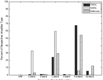
pro-vided for every satellite and amplifier. Figure 3 shows the operating frequency breakdown of the 18,902
amplifiers. The highest percentage of TWTAs, 68%, and unknown amplifier types, 55%, falls in Ku-band.
For SSPAs, the highest percentage of SSPAs, 60%, operates in C-band. Onlyfive ultra high frequency
amplifiers were recorded among the 565 satellites, and these were not designated as SSPA or TWTA.
As previously mentioned, the Boeing 2005 study, which included 944 SSPAs, found that SSPA
tech-nology with low enough mass and high efficiency was not available for high-frequency demands [11].
Figure 3. Frequency breakdown of traveling wave tube amplifiers (TWTAs), solid-state power amplifiers (SSPAs), and amplifiers of unknown type. TWTAs appear to dominate higher frequencies and SSPAs in lower frequencies (C-band and below). However, we note that there are still SSPAs being used for some high-frequency
(Ku-band) applications.
Table II. Communications satellite and payload data summary.
Parameter Value
Total satellites 565
LEO satellites 16
GEO satellites 549
Entirely TWTA payloads 226
Entirely SSPA payloads 19
TWTA/SSPA hybrid payloads 60
LEO, low earth orbit; GEO, geostationary orbit; TWTA, traveling wave
Figure 3 shows that of the 2158 SSPAs considered here, that SSPAs were in fact used for frequencies as high as Ku-band, and the percentage of SSPAs in Ku-band increased from approximately 1% in Boeing 2005, 2008, and 2013 studies to 6% in this work.
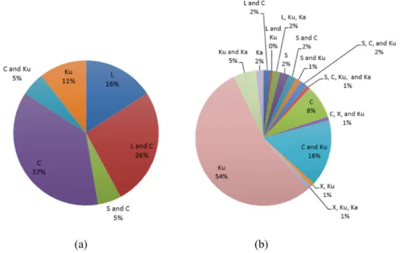
Figure 4 shows the frequency breakdown of the satellites that have (1) exclusively SSPA payloads;
and (2) exclusively TWTA payloads. The significant difference in the number of exclusively SSPA
payloads compared with the number of exclusively TWTA payloads, 19 versus 226, respectively, also
is a reflection of the variety of payload power and frequency band combinations. We note that there
were no exclusive SSPA Ka-band payloads. Thisfinding is consistent with the Boeing 2005 study,
which claimed SSPAs were not available for high frequencies but would be a metric to reexamine in future studies. On the other hand, there were also no exclusive TWTA L-band payloads.
The percentage of exclusively TWTA payloads that consist of a single L-band transponder make up only 4% of all the exclusively TWTA payloads. The largest percentage of exclusively SSPA payloads operates at C-band, and the largest percentage of exclusively TWTA payloads operates at Ku-band. Note that Figure 3 depicts the operating frequency breakdown of all SSPAs, whereas Figure 4 depicts the frequency breakdown of exclusively SSPA payloads.
5.2. Amplifier output power
The output power of an amplifier is one of the key performance characteristics. Figure 5 shows the
maximum output power of each of the three amplifier types for a particular frequency band. There
was no available data for SSPAs that operate at X-band or Ka-band.
The variability in the maximum output power capability of the SSPAs and TWTAs does not support
the 1991 ESTEC study, which claimed that RF power output levels were similar for both amplifier
technologies. As expected, the TWTAs provide higher output power capabilities at higher frequency bands, and SSPAs generate higher output powers at lower frequency bands. This is evident in L-band, where the SSPA with highest output power produced 150 W, compared with the L-band TWTA with a highest output power of 45 W. The 150 W SSPA was onboard Optus B1, launched in 1992; the second highest output power for SSPAs was 38 W and was onboard both the AMSC 1 and MSat 1 satellites. It is important to note that the Optus B1 output power is likely an anomalously high data point. It is also
Figure 4. Frequency distribution of (a) payloads that are exclusively solid-state power amplifiers (19 out of 305 payloads) and (b) payloads that are exclusively traveling wave tube amplifiers (226 out of 305 payloads).
evident in the Ku-band, where the SSPA with the highest output power produced 63 W, compared with the maximum output power for the TWTA of 250 W.
The 1993 NASA study found that 66 W was the highest output power for Ku-band TWTAs and that 17 W was the highest output power for both C-band SSPAs and TWTAs. Figure 5 depicts an increase in the maximum output power capability for Ku-band TWTAs to higher than 180 W, more than a 250% increase. We also note an increase in the maximum C-band output power capabilities of both SSPAs
and TWTAs. Specifically, there is a 282% increase for C-band SSPAs, which reached a maximum
output power of 48 W, and more than a 1000% increase for C-band TWTAs, which reached a maximum output power of 228 W.
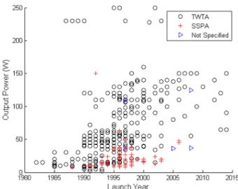
Figure 6 shows the output powers for all TWTAs, SSPAs, and amplifiers of unspecified type with
available output power data. The general claim that SSPAs are used for lower output powers compared
with TWTAs is supported. Wefind a general increase in the TWTA output power capability with time
Figure 5. Frequency breakdown of maximum output power (W) for solid-state power amplifier (SSPA) and trav-eling wave tube amplifier (TWTA) payloads.
Figure 6. Output power (W) of amplifiers onboard satellites with traveling wave tube amplifiers (TWTAs) (marked with a black o), solid-state power amplifiers (SSPAs) (marked with a red +), and unspecified payloads
for moderately high-power TWTAs; the TWTAs with output powers specified above 200 W did not increase. Output power data for SSPAs were not available after 2006.
Strauss noted that both SSPAs and TWTAs could be used for an RF output power of 15–50 W [8].
Figure 9 supports this claim from 1987 to 2006, yet after 2003, the lowest output power cited for a TWTA was 55 W.
The 1993 NASA study suggested that SSPAs were more commonly used in C-band for RF output
powers of 20–40 W and that TWTAs were more common for RF output powers between 50–70 W.
From Figure 8, the highest output power of a C-band SSPA is observed to be 34 W. In Figure 9, it
is clear that the number of TWTAs with an RF output power between 50–70 W is greater than the
num-ber of SSPAs with the same range of output powers.
5.3. Amplifier redundancy
As shown in Table I of Section 4 with the 1991 ESTEC study, the level of amplifier redundancy
de-signed in a system can serve as an indicator for the expected reliability of the component. However, redundancy was not analyzed in any of the other studies included in Table I. Figure 7 shows the
num-ber of redundant TWTAs, SSPAs, and amplifiers of unspecified type onboard satellites with launch
dates from 1982 to 2016. The specific redundancy schemes, such as the one given in the 1991 ESTEC
study (SSPA 6:5 and TWTA 3:2), are not identified in our analysis. Redundancy data for SSPAs were
not available after year 2000.
The number of SSPA amplifiers shown in Figure 7 is greater than 19, the total number of
exclu-sively SSPA payloads. This is because data from hybrid payloads, consisting of both SSPAs and TWTAs, were also included in this analysis. It is interesting to note that the highest number of
redun-dant amplifiers reached a total of 20 for TWTAs, 12 for SSPAs, and 22 for unspecified amplifier type.
The payload equipped with 20 redundant TWTAs consisted of eight TWTAs that operated in C-band and 12 TWTAs that operated in Ku-band. The payload equipped with 12 redundant SSPAs and the
payload equipped with 22 redundant amplifiers of unspecified type both operated in C-band.
Figure 8 expands upon Figure 5 to show the ratio of the number of operational amplifiers to the
number of redundant amplifiers for the three amplifier types (SSPA, TWTA, and unspecified). Figure 8
does not include two outlier satellites, Thuraya 1 and Thuraya 2 satellites launched in 2000 and 2003, each with 125 C-band TWTAs and two spares, and thus a ratio of operational TWTA to redundant TWTA equal to 62.5.
The ratio of operational to redundant SSPAs never exceeded a ratio of 6, whereas the ratio of oper-ational to redundant TWTAs reached as high as 27 (shown in Figure 8), with two outlier points of 62.5
that are not shown in Figure 8. Two unspecified payloads were designed with an operational to
Figure 7. Number of redundant amplifiers onboard satellites with traveling wave tube amplifiers (TWTAs) (marked with a black o), solid-state power amplifiers (SSPAs) (marked with a red +), and unspecified payloads
redundant amplifier ratio of 32. On average, the ratio of operational to redundant TWTAs is 5.13, and the ratio of operational to redundant SSPAs is 0.47. Unfortunately, the data gathered for this study do not contain information on redundancy for payloads designated as either SSPA or TWTA after 2005. However, for both the worst-case and average scenarios, the ratio or operational to redundant ampli-fiers is 10 times higher for TWTAs than SSPAs. This suggests that TWTAs are more considered
and more reliable, as they are equipped with fewer redundant amplifiers.
5.4. Amplifier bandwidth
The bandwidth of the amplifier is another important performance characteristic for communication
sat-ellites because it indicates the range of frequencies over which data are transmitted. Wider bandwidth transponders, currently capable of hundreds of MHz, provide more power and higher data rates, at the expense of increased size and weight.
None of the studies presented in Table I include a comparison of the bandwidth capabilities for
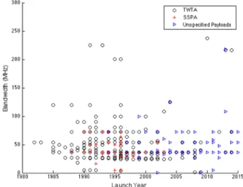
the amplifiers. Figure 9 shows the bandwidth, measured in MHz, for the three amplifier types.
Figure 8. Ratio of operational to redundant amplifiers onboard satellites with traveling wave tube amplifiers (TWTAs) (marked with a black o), solid-state power amplifiers (SSPAs) (marked with a red +), and unspecified
payloads (marked with a blue triangle).
Figure 9. Bandwidth (MHz) of amplifiers onboard satellites with traveling wave tube amplifiers (TWTAs) (marked with a black o), solid-state power amplifiers (SSPAs) (marked with a red +), and unspecified payloads (marked with a blue triangle). The majority of all payloads operate with bandwidths of less than 100 MHz, which
One outlier is not included in this figure; the outlier was onboard the advanced communications test satellite launched in 1993 with four Ka-band TWTAs that operated with a bandwidth of 800 MHz.
Bandwidth data exist for only one out of the 19 exclusively SSPA payloads and for only 15 out of
the 226 exclusively TWTA payloads after 2005. Therefore, it is difficult to make conclusions on the
trends in bandwidth over time. However, the majority of all three amplifier types operate with
band-widths below 100 MHz, which is likely the result of technology limitations. Seven SSPAs operated at a bandwidth of 72 MHz, which was the highest bandwidth for an SSPA. As previously mentioned, the highest bandwidth for a TWTA was 800 MHz, but this point was not included in Figure 9. The highest bandwidth for a TWTA that is included in Figure 9 is 237 MHz, which was onboard KA-SAT launched in 2010.
The recent launch of satellites like Europe’s KA-SAT, equipped with wide bandwidth transponders,
and other programs like the US’ Viasat1, which intends to provide high-speed Internet services, are
evidence of a growing trend toward wider band devices. Previously, bandwidth was limited by the available frequency-dependent transponder technologies. Today, transponders with bandwidths of 500 MHz are desired in order to decrease communication burst sizes to microsecond counts. This in turn reduces the amount of time receiving antennas need to be powered up. Wider band transponders
are also beneficial for single carrier operation, because they provide high-data rates without the
intermodulation penalties that arise with multi-carrier mode operation. The disadvantage with wider band transponders operating in single carrier mode is that the terminal demodulators have to use sophisticated waveforms to not overwhelm the demodulation/decoding chain.
6. ANALYSIS OF COMMUNICATIONS SATELLITE POWER AMPLIFIER FAILURE RATES
In this study, we also analyze spacecraft telemetry from power amplifiers onboard 16 geostationary
communications satellites from the Inmarsat and Telenor satellitefleets. Amplifier reliability is
deter-mined through analysis of anomaly logs and analysis of satellite telemetry (specifically amplifier
current), prior to the anomaly. Anomaly logs are consulted for the age of the device at the time of
the anomaly, and the amplifier current levels prior to amplifier anomalies are used to distinguish
between hard and soft failures.
The 16 satellites have a combined total of 659 amplifiers: 124 TWTAs and 535 SSPAs. The 124
TWTAs consisted of 92 Ku-band TWTAs, 24 L-band TWTAs, and eight C-band TWTAs. Of these, three Ku-band TWTAs, eight L-band TWTAs, and four C-band TWTAs were spares. The 535 SSPAs consisted of 525 L-band SSPAs and 10 C-band SSPAs, of which, 33 L-band SSPAs were spares. Of the 124 TWTAs, two TWTA failures occurred, each on separate satellites. The two TWTA anomalies both
occurred within thefirst 2 years of operation. Of the 535 SSPAs, 26 SSPA anomalies occurred, taking
place anywhere from within thefirst 3 months of operation to 15 years after launch [29].
In this group, the SSPAs operate at L-band or C-band, and the TWTAs operate at L-band, C-band,
or Ku-band. One of the TWTA failures occurred for a Ku-band amplifier and the other occurred on an
L-band amplifier. The Boeing 2005 study found that 100% of their TWTA anomalies were in Ku-band
and that the SSPA anomalies were primarily in C-band. Of the 535 SSPAs in our study, 26 SSPA failures occurred, with 100% occurring at L-band. This is expected as more than 98% of the SSPAs in this analysis operated at L-band.
The Boeing 2005 study also found that 83% of the satellites experienced zero TWTA anomalies, and 80% of the satellites recorded zero SSPA anomalies. Of the 20% of satellites that did experience SSPA anomalies, only 9% experienced more than two SSPA anomalies per satellite. Of the 16 satellites in our study, half of the satellites are exclusively TWTA payloads, and the other half of the satellites are exclusively SSPA payloads. Six out of the eight (75%) exclusively TWTA payloads experienced zero TWTA anomalies, and only one of the eight (13%) exclusively SSPA payloads experienced zero SSPA anomalies. Seven of the eight SSPA payload satellites experienced at least one anomaly, and six of the eight (75%) SSPA payload satellites experienced anywhere from two to eight SSPA anomalies.
Section 3.1 gives insight into the different failure types for SSPAs: hard and soft failures. TWTAs
failures are typically‘hard failures’, and thus, the distinction between hard and soft failures is not
com-mon. Hard failures occur when an excessively low-current or high-current measurement breaches a
specified current threshold, and the device loses ability to operate. The anomaly thresholds are often
amplifier and operator specific. For the 26 SSPA anomalies, 22 of the anomalies or 86% experienced
hard failures. Only one of the four SSPAs that experienced a soft failure was recoverable. Therefore, 25
out of 26 of the SSPA anomalies required a redundant amplifier to be switched on [29]. The two
TWTA anomalies were hard failures. The Boeing 2005 study stated that a single satellite component failure has essentially zero impact on the communications function. While the ability to turn on
redundant amplifiers often alleviates the impact of amplifier failures, issues do arise when a satellite
utilizes all available redundant amplifiers. This has not yet been experienced on any of the 16 satellites.
However, there were three amplifier anomalies for which a redundant amplifier was already in use, and
thus not available, due to a previous amplifier failure.
More detailed satellite payload data are necessary for conclusions to be drawn; however, there is a
clear difference between the number of amplifier anomalies described in the 2005 Boeing study of 104
satellites (1783 TWTAs and 944 SSPAs) and the 16 satellites (124 TWTAs and 535 SSPAs) of this analysis. One potential explanation for this difference could be related to the fact that as technological capabilities evolve (e.g. smaller feature sizes), the susceptibility of newer technologies to radiation also increases [43, 44].
7. CONCLUSION
For communications satellites, RF power amplifiers consume 80–90% of the spacecraft bus power as
the key component in the communications payload [7, 8]. The two primary amplifier technologies are
TWTAs and SSPAs. TWTAs are electron devices that consist of an EPC and a TWT, and are generally more advantageous for higher power and higher frequencies. These devices tend to survive beyond
their 15–20 year life expectancy, with failures typically within the first 5 years of operation [2, 4, 13,
15, 20, 21]. SSPAs are generally used at lower operating frequencies [5]. SSPAs contain an EPC
and numerous parallel FETs for RF power amplification [6]. SSPA failures tend to occur because of
extended use and high heat loads. Overall, SSPAs are considered advantageous in terms of mass
and cost but are not as efficient as TWTAs at high frequencies [30, 31]. In the near future, GaN SSPAs
are expected to deliver high efficiencies at a reduced size, cost, and with improved thermal
perfor-mance compared with GaAs SSPAs [6].
Prior to this work, there have beenfive major studies comparing SSPA and TWTA technologies;
these studies were conducted by the ESTEC (1991), NASA (1993), and Boeing (2005, 2008, and 2013). They suggested that SSPAs were not contenders for the high-power and high-frequency appli-cations where TWTAs were typically used [11, 8]. All studies saw an improvement in reliability of both devices, or decrease in FITs over time, and three of the studies reported TWTA FITs to be lower
than SSPA FITs. We compared the results of thefive previous studies on SSPA and TWTA
technol-ogies with similar analyses using updated data gathered from Seradata’s Spacetrak and Gunter’s Space
Page. In addition, we also evaluate payload capability. Specifically, we include analyses of amplifier
frequency, output power, number of redundant amplifiers, and bandwidth from 565 communications
satellites launched between 1982 and 2016. Of the 565 satellites considered, 260 satellites had
unspec-ified amplifiers, and 305 satellites had payloads that were exclusively TWTA, exclusively SSPA, or a
combination of both technologies. Of the 305 satellites with clearly identified payloads, 226 satellites
(74%) were exclusively TWTA payloads, 19 satellites (6%) were exclusively SSPA payloads, and 60
satellites (20%) were hybrid payloads. A total of 18,902 amplifiers including 6428 TWTAs, 2158
SSPAs, and 10,316 amplifiers of unspecified type were included in this analysis. Of the 18,902
ampli-fiers, 68% of the TWTAs and 55% of the unspecified amplifier types operated at Ku-band. Only 4% of the TWTA payloads operated at L-band. The largest percent of SSPAs, 60%, operated in C-band, and
none of the SSPAs operated in Ka-band. These findings support the Boeing 2005 study, which
suggested that SSPAs were not commonly used for high-frequency and high-power applications where TWTAs were typically utilized.
The maximum output power capability for TWTAs exceeded 200 W in C-band, S-band, and Ku-band, and peaked at 250 W for C-band and Ku-band. For SSPAs, the maximum output power
peaked at 150 W for L-band. Thisfinding does not support the 1991 ESTEC conclusion that power
output levels were similar for both amplifier types. Since the 1991 ESTEC study, there has been an
increase in maximum output power capability of 250% for Ku-band TWTAs, more than 280% for C-band SSPAs, and more than 1000% for C-band TWTAs.
In this work, we considered amplifier redundancy design as an indicator of the expected reliability
of a satellite component, an approach that was not taken in thefive previous studies. It should be noted
that in our study, redundancy data were not available in either Gunter’s Space page or Seradata’s
Spacetrak for payloads specified as SSPA or TWTA launched after 2005. The ratio of operational
amplifiers to redundant amplifiers for TWTA payloads reached more than 10 times the ratio of the
SSPA payloads (62.5 for TWTAs vs. six for SSPAs). Therefore, higher redundancy for SSPA payloads compared with TWTA payloads could suggest higher expected reliability for TWTAs.
We also considered bandwidth in this study, a parameter that was also not directly addressed in the
previous five studies. Because of limited bandwidth data from our sources, (only available for one
exclusively SSPA payload and for 15 TWTA payloads), we did not draw conclusions on bandwidth capability over time. However, trends toward wider bandwidth devices are expected with the current drive to provide high-speed data via satellites like KA-SAT and Viasat1.
To understand more about component failure and reliability, we assessed the anomaly logs for age at time of failure from 16 geostationary communications satellites. The 16 satellites consisted of a
combined total of 659 amplifiers, of which 124 were TWTAs and 535 were SSPAs. Only two of the
124 TWTAs failed, one Ku-band and one L-band; both failures occurred in thefirst 2 years of
opera-tion. Of the 535 SSPAs, 26 experienced anomalies, which occurred between 3 months and 15 years of operation; 100% of the SSPA anomalies occurred at L-band, which is expected as 98% of the SSPAs included in this analysis operated at L-band. More than 85% of the SSPA anomalies were hard failures, and only one of the four SSPA soft failures was recoverable. Thus, a total of 25/26 SSPA anomalies
required a redundant amplifier. The Boeing 2005 study claimed that a single component failure has
essentially zero impact on the satellite’s communication capability. There were three instances in
which the intended redundant SSPA was already in use because of a previous amplifier anomaly. These
findings and the fact that network engineering is required to sustain communications service and
performance levels indicate that failures may have some impact on the satellite’s capability. While
safeguards and systems exist to reduce the impact of failures on performance to levels that approach zero, this is not entirely without impact or effort.
Based on the 16 payloads that had bandwidth data, we observed that SSPAs had a higher total
percentage of failures onboard satellites and that these payloads required more redundant amplifiers
in comparison with TWTA payloads. Overall, however, more data are required to make a clear conclu-sion based on operational failures as a greater population size than 16 is needed to improve statistics.
Advances in communication amplifier technology are required as user demands for higher data rates
and increased bandwidth continue to grow. SSPAs and TWTAs must not only continue to develop with innovative adjustments to previous designs but must also improve beyond their current capability limits in
reliability, efficiency, and operating frequency as well as size, weight, and power. Based only on amplifier
redundancy data and failure percentages, this study suggests TWTAs are currently a more reliable choice. While enough data were available to enable our initial analyses, these analyses cannot be considered conclusive because additional data would improve statistics. Future studies must be conducted with larger, more complete, and detailed data sets that cover all of the parameters of interest in order to generate a comprehensive conclusion regarding SSPA versus TWTA selection, as well as updated periodically as technology evolves.
ACKNOWLEDGMENTS
The authors would like to thank Inmarsat and Telenor for their support in providing data for this analysis, as well as Barry Manz, Gaston Lehu, Michael Kaliski, Kevin Daniels, and Michael Tseytlin for the useful discus-sions. The authors would also like to acknowledge the Air Force Office of Sponsored Research (AFOSR) Grant FA9550-13-1-0099 and the National Science Foundation (NSF) for funding this work.
REFERENCES
1. Aloisio M, Angeletti P, Coromina F, Deborgies F, Gaudenzi R, Ginesi, A. R&D challenges for broadband Satcoms in 2020.
In IEEE International Vacuum Electronics Conference: Monterey, California, 2010; 18–20. DOI: 10.1109/
IVELEC.2010.5503426
2. Robbins NR, Christensen JA, Hallsten UR. Performance and reliability advances in TWTA high power amplifiers for
com-munications satellites. In Military Comcom-munications Conference, 2005. MILCOM 2005: Atlantic City, NJ, 17-20, 2005;
1887–1890. DOI: 10.1109/MILCOM.2005.1605948
3. Murthy HS, Sharma A, Badarinarayana K, Lakshminarasimhan P. Thermal management of GEO satellite communication
payload. In IEEE International Vacuum Electronics Conference: Bangalore, India, 2011; 21–24. DOI: 10.1109/
IVEC.2011.5747079
4. Bijeev NV, Malhotra A, Kumar V, Singh S, Dasgupta KS, Motta RN, Venugopal B, Sandhyarani, Jinan OK, Jayakumar BK. Design and realization challenges of power supplies for space TWT. IEEE International Vacuum Electronic Conference:
Bangalore, India, 2011; 21–24. DOI: 10.1109/IVEC.2011.5747079
5. Kaliski M. Evaluation of the next steps in satellite high power amplifier technology: flexible TWTAs and GaN SSPAs. In
IEEE International Vacuum Electronics Conference: Rome, Italy, 2009; 28–30. DOI: 10.1109/IVELEC.2009.5193398
6. Colantonio P, Giannini F, Limiti E. High efficiency RF and microwave solid state power amplifiers. John Wiley & Sons,
Ltd.: West Sussex, United Kingdom, 2009.
7. Illokken E. TWT reliability in space. Aero El Sys Mag, IEEE 1987;2(7):22–24. doi:10.1109/MAES.1987.5005442.
8. Strauss R. Orbital performance of communication satellite microwave power amplifiers (MPAs). Int J Satell Comm 1993;
11:279–285. doi:10.1002/sat.4600110506.
9. Komm DS, Benton RT, Limburg HC, Menninger WL, Zhai X. Advances in space TWT efficiencies. IEEE T Electron Dev
2000;48(1):174–176. DOI: 10.1109/16.892186
10. Rapisarda M, Colzi E, Angeletti P, Aloisio M. 4.1: navigation traveling wave tube amplifiers-trade-off aspects. In IEEE
Vacuum Electronics Conference (IVEC): IEEE, 2010; 47–48. DOI: 10.1109/IVELEC.2010.5503609
11. Weekley JM, Mangus BJ. TWTA versus SSPA: a comparison of on-orbit reliability data. IEEE T Electron Dev 2005;52
(5):650–652. doi:10.1109/TED.2005.845864.
12. Strauss R. Reliability of SSPA’s and TWTA’s. IEEE T Electron Dev 1994; 41(4):625–626. doi:10.1109/16.278524.
13. Mallon KP. PL.6: TWTAs for satellite communications: past, present, and future. In IEEE International Vacuum Electronic
Conference: Monterey, California, 2008; 14–15. DOI: 10.1109/IVELEC.2008.4556558
14. Cuignet E, Tonello E, Maynard J, Boone P. Very high efficiency dual flexible TWTA, a flexible concept allowing to deal
with performances and schedule constraints of telecommunication payloads. IEEE Vacuum Electronics Conference (IVEC):
IEEE, 2013; 1–2. DOI: 10.1109/IVEC.2013.6570951
15. Coaker B, Challis T. Traveling wave tubes: modern devices and contemporary applications. Microwave J 2008;51(10):32–46.
16. Qiu JX, Levush B, Pasour J, Katz A, Armstrong CM, Whaley DR, Tucek J, Kreischer K, Gallagher D. Vacuum tube ampli-fiers. IEEE Microw Mag 2009; 10(7):38–51. DOI: 10.1109/MMM.2009.934517
17. Mallet A, Anakabe A, Sombrin J. Multiport-amplifier-based architecture versus classical architecture for space
telecommu-nication payloads. IEEE T Microw Theory 2006;54(12):4353–4361. DOI: 10.1109/TMTT.2006.885904
18. Menninger WL, Eze DC, Hollister RS, Martin RH. High-efficiency, 200-W Ku-band traveling-wave tubes for satellite
communications downlinks. In IEEE Vacuum Electronics Conference: IEEE, 2013; 1–2. DOI: 10.1109/
IVEC.2013.6571081
19. Robbins N, Dibb D, Menninger W, Zhai X, Lewis D. Space qualified, 75-watt V-band helix TWTA. International Vacuum
Electronics Conference: Monterey, California, 2012; 24–26. DOI: 10.1109/IVEC.2012.6262190
20. Nicol EF, Mangus BJ, Grebliunas JR. TWTA versus SSPA: analysis update of the Boeingfleet on-orbit reliability data. In
IEEE International Vacuum Electronics Conference: Monterey, California, 2008; 22–24. DOI: 10.1109/
IVELEC.2008.4556435
21. Feicht JR, Loi KN, Menninger WL, Nicolello JG, Zhai X. Space qualified 140 W linearized L-band helix TWTA. In IEEE
International Vacuum Electronics Conference: Monterey, California, 2012; 24–26. DOI: 10.1109/IVEC.2012.6262193
22. Manz B. Advancing TWT technology. J Electron Defense 2009;32(7):26–30.
23. Aloisio M, Angeletti P, Colzi E, D’Addio S, Balague R, Casini E, Coromina F. End-to-end performance evaluation
methodology for TWTA-based satelliteflexible payloads. In IEEE International Vacuum Electronic Conference: Monterey,
California, April 2008; 22–24. DOI: 10.1109/IVELEC.2008.4556438
24. L-3 Communications. LTWTA product sheets, space TWTs, LTWTAs, & EPCs. [online] http://www2.l-3com.com/eti/ product_lines_space_twt.htm [retrieved 21 Jan 2014].
25. Taylor GW, Bayruns RJ. A comparison of Si MOSFET and GaAs MESFET enhancement/depletion logic performance.
IEEE T Electron Dev 1985;32(9):1633–1641. doi:10.1109/T-ED.1985.22173.
26. Sze SM. Semiconductor Devices Physics and Technology. John Wiley & Sons, Ltd.: New York, 2001.
27. Pavlidis D. HBT vs. PHEMT vs. MESFET: what’s best and why. Compound Semiconductors 1999; 5(5):56–59. DOI:
10.1117/12.373015
28. Airbus Defence and Space. Airbus defence and space L/S band SSPA data sheet. SSPA– L/S Band for Mobile
Communi-cations Satellites [online], http://www.astrium.eads. net/en/equipment/sspa-ls-band-sspa-for-mobile-communiCommuni-cations-satel- net/en/equipment/sspa-ls-band-sspa-for-mobile-communications-satel-lites.html [retrieved 21 Jan 2014].
29. Lohmeyer W, Cahoy K. Space weather radiation effects on geostationary satellite solid-state power amplifiers. AGU Space
Weather 2013;11:476–488. doi:10.1002/swe.20071.
30. Escalera N, Boger W, Denisuk P, Dobosz J. Ka-band, 30 watts solid state power amplifier. IEEE MTTS Int Microw Symp
2000;1(11–16):561–563. doi:10.1109/MWSYM.2000.861123.
31. Sechi F, Bujatti. Solid-state Microwave High-power Amplifiers. Norwood, Mass: Artech House, 2009.
32. Raab FH, Asbeck P, Cripps S, Kenington PB, Popovic ZB, Pothecary N, Sevic JF, Sokal NO. RF and microwave power
amplifier and transmitter technologies. Part I. High Freq Electron 2003; 2(3):22–36. DOI: 10.1109/22.989965
33. Thales Alenia Space. CAMP-SSPA Thales Group. Thales Alenia Space SSPA, [online] https://www.thalesgroup.com/sites/
34. Airbus Defence and Space. C-Band SSPA for communication satellites. About Amplifiers [online], http://www.astrium.eads.
net/en /equipment/about-amplifiers.html [retrieved 21 Jan 2014].
35. NEC TOSHIBA Space Systems, Ltd.. High linearity SSPA line up– L-band SSPA. High Linearity SSPA Line Up [online],
http://www.nec.com/en/global/solutions/space/ satellite_communications/images/L-band_SSPA.pdf [retrieved 21 Jan 2014].
36. NEC TOSHIBA Space Systems, Ltd.. High linearity SSPA line up– S-band SSPA. High Linearity SSPA Line Up [online],
http://www.nec.com/en/global/solutions/ space/satellite_communications/images/S-band_SSPA.pdf [retrieved 21 Jan 2014]. 37. NEC TOSHIBA Space Systems, Ltd.. C-band SSPA. C-band SSPA [online], http://www.nec.com/en/global/solutions/space/
satellite_communications/images/C-band_SSPA.pdf [retrieved 21 Jan 2014].
38. Mitsubishi Electric (Melco). C-band solid state power amplifier 50–70 W class. Satellite Components [online], http://www.
mitsubishielectric.com/bu/space/products/satellite/rf_ equipment/index.html [retrieved 21 Jan 2014].
39. Sahu K. EEE-INST-002: instructions for EEE parts selection, screening, qualification, and derating
NASA/TP-2003-212242: NASA, 2008.
40. Airbus Defence and Space. 85 W S-band GaN SSPA data sheet. About Amplifiers [online], http://www.astrium.eads.net/en/
equipment/about-amplifiers.html [retrieved 21 Jan 2014].
41. Airbus Defence and Space. 80 W C-band GaN SSPA for communication satellites. About Amplifiers [online], http://www.
astrium.eads.net/en/equipment/about-amplifiers .html [retrieved 21 Jan 2014].
42. Nicol EF, Mangus BJ, Grebliunas JR, Woolrich K, Schirmer JR. TWTA versus SSPA: a comparison update of the Boeing
satellitefleet on-orbit reliability. In IEEE International Vacuum Electronics Conference: Paris, France, May 2013; 21–23.
DOI: 10.1109/IVEC.2013.6571087
43. Baker DN. The occurrence of operational anomalies in spacecraft and their relationship to space weather. IEEE Trans
Plasma Sci 2000;28(6):2007–2016. doi:10.1109/27.902228.
44. Love DP, Toomb DS, Wilkinson DC, Parkinson JB. Penetrating electronfluctuations associated with GEO spacecraft
anomalies. IEEE Trans Plasma Sci 2000;28:2075–2084. doi:10.1109/27.902234.
AUTHORS' BIOGRAPHIES
Whitney Q. Lohmeyer received a BS in Aerospace Engineering from North Carolina State University in 2011 and an SM in Aerospace Engineering from Massachusetts Institute of Technology (MIT) in 2013. She is currently pursuing her PhD in Aerospace Engineering. She is a National Science Foundation graduate research fellow.
Raichelle J. Aniceto is a second year undergraduate student at MIT and is currently pursuing her BS in Aerospace Engineering.
Kerri L. Cahoy received a BS in Electrical Engineering from Cornell University in 2000, an MS in Electrical Engineering from Stanford University in 2002, and a PhD in Electrical Engineering from Stanford in 2008. After working as a senior payload and communication sciences engineer at Space Systems Loral, she completed a National Aeronautics and Space Administration (NASA) postdoctoral program fellowship at NASA Ames Research Center and held a research staff appointment with MIT/NASA Goddard Space Flight Center. She is currently a Boeing assistant professor in the MIT Department of Aeronautics and Astronautics with a joint appointment in the Department of Earth and Planetary Sciences at MIT.
![Figure 1. L-3 Communications Electron Technologies, Inc. traveling wave tube ampli fi er (TWTA) devices: (a) Ku-band TWT [18] and (b) V-band TWTA [19].](https://thumb-eu.123doks.com/thumbv2/123doknet/14389855.507974/3.892.240.659.97.266/figure-communications-electron-technologies-traveling-ampli-twta-devices.webp)
![Figure 2. Airbus Defence and Space (formerly Astrium) L/S Band solid-state power ampli fi er for mobile commu- commu-nications satellites [28].](https://thumb-eu.123doks.com/thumbv2/123doknet/14389855.507974/6.892.322.571.98.293/figure-airbus-defence-space-astrium-mobile-nications-satellites.webp)