HAL Id: hal-03126521
https://hal.archives-ouvertes.fr/hal-03126521
Submitted on 31 Jan 2021
HAL is a multi-disciplinary open access
archive for the deposit and dissemination of
sci-entific research documents, whether they are
pub-lished or not. The documents may come from
teaching and research institutions in France or
abroad, or from public or private research centers.
L’archive ouverte pluridisciplinaire HAL, est
destinée au dépôt et à la diffusion de documents
scientifiques de niveau recherche, publiés ou non,
émanant des établissements d’enseignement et de
recherche français ou étrangers, des laboratoires
publics ou privés.
Towards a high MnO2 loading and gravimetric capacity
from proton-coupled Mn4+ /Mn2+ reactions using a 3D
free-standing conducting scaffold
Arvinder Singh, Ozlem Sel, Hubert Perrot, Véronique Balland, Benoît
Limoges, Christel Laberty-Robert
To cite this version:
Arvinder Singh, Ozlem Sel, Hubert Perrot, Véronique Balland, Benoît Limoges, et al.. Towards a
high MnO2 loading and gravimetric capacity from proton-coupled Mn4+ /Mn2+ reactions using a
3D free-standing conducting scaffold. Journal of Materials Chemistry A, Royal Society of Chemistry,
2021, 9 (3), pp.1500-1506. �10.1039/D0TA10685B�. �hal-03126521�
1
Towards a high MnO
2loading and gravimetric capacity from proton-coupled
Mn
4+/Mn
2+reactions using 3D free-standing conducting scaffold
Arvinder Singh,
aOzlem Sel,
bHubert Perrot,
bVéronique Balland,
cBenoît Limoges,
cand Christel
Laberty-Robert*
,aa
Chimie de la Matière Condensé, Sorbonne Université - CNRS, UMR 7574, 4 place Jussieu, 75005 Paris, France b
Laboratoire Interfaces et Systèmes Electrochimiques (LISE), Sorbonne Université - CNRS, UMR8235, 4 place Jussieu, 75005 Paris, France.
c
Université de Paris, Laboratoire d’Electrochimie Moléculaire, UMR CNRS 7591, F-75013 Paris, France.
We highlight 3D free-standing electrospun CNF electrodes as a superior conductive scaffold for the highly reversible proton-coupled MnIV(s) MnII(aq) conversion in a mild aqueous buffered electrolyte (pH 5).
Electrochemical quartz crystal microbalance is used to in-situ monitor these conversion reactions on the non-transparent CNF electrodes. Free-standing CNFs allows for a remarkably high relative MnO2 loading (63%,
equivalent to a mMnO2/mCNF ratio of 1.7) at a maximal charge of 1.4 mA·h/cm2, while keeping a C.E. ≥ 95%
over 300 cycles. The gravimetric capacity of the complete cathode is thus as high as 338 mA·h/gMnO2+CNF (i.e.,
534 mA·h/gMnO2), outperforming the current state-of-the-art based conventional graphite/carbon felts as
substrates (< 30% MnO2 loading, < 0.4 mMnO2/mCNF ratio and < 150 mA·h/gMnO2+substrate) or composite
electrodes. Furthermore, the buffered electrolyte allows for remarkably highly constant deposition-dissolution potentials with low hysteresis (0.16 V). Pairing 3D electrospun CNFs (diameter ≤ 200 nm) and mild aqueous buffered electrolytes is thus a striking approach towards the development of MnO2-based mild
aqueous batteries with high energy efficiency.
The intense interest in manganese oxides (MnO2) for aqueous batteries is driven by their high theoretical gravimetric capacity of 617 mA·h/g (Mn4+ Mn2+), abundant earth reserves, eco-friendliness, and low cost compared to other metal oxides (e.g., Ni- and Co-oxides) based cathodes.1-3 Recently, the two electrons reversible conversion reactions of Mn4+ to Mn2+ have been demonstrated under extreme pH conditions.4-6 However, the use of such conditions imposes several practical challenges on the development of large-scale devices due to safety concerns. Therefore, there is a growing scientific quest for the development of aqueous Zn-MnO2 batteries operating in mild aqueous electrolytes. However, in such systems, full utilization of capacity from a complete reduction of Mn4+ to Mn2+ is rare as evidenced by gravimetric capacities below 400 mA·h/gMnO2.7, 8 Besides, the charge storage mechanism occurring at the MnO2 cathode remains a matter of debate, especially regarding the reversible insertion of Zn2+ cations.9 An alternative mechanism involving the reversible electrodeposition-electrodissolution of MnO2 has recently emerged. Because relying on proton-coupled electron transfers, this reaction is associated with significant local pH gradients, triggering precipitation of zinc hydroxides and restricting the gravimetric capacity, as well as to potential drifts. 10-13
To overcome these limitations, Mateos et al. demonstrated the benefit of using a buffered aqueous electrolyte (pH = 5) to fully convert MnO2 to water-soluble Mn2+(aq) at stable potential values and with low hysteresis through the highly reversible proton-coupled reaction given below:14, 15
MnO2(s) + 4 AH + 2 e- ⇋ Mn2+(aq) + 4 A- + 2 H2O (1)
where AH and A- are the weak Brønsted acid and base of the buffer, respectively. When performed on transparent 2D ITO electrodes, accumulation of an electrochemically inactive fraction of MnO2 (ca. 20 wt% of the total deposited amount) is reported, as attested by in-situ UV-visible absorption spectroscopy and postmortem inductively coupled plasma atomic emission spectrometry (ICP-AES) quantification, leading thus to a subsequent decrease of the gravimetric capacity.14 This issue was recently solved using transparent 3D ITO electrodes as a conductive mesoporous scaffold for the electrodeposition-electrodissolution of MnO2, leading to a significant improvement of the reversible gravimetric capacity up to 560 mA·h/gMnO2.15 However, while such model ITO-based electrodes are of great interest for fundamental quantitative studies, they do not allow to switch to operational batteries. For such purpose, a conductive scaffold combining high specific surface electroactive area
2
and an easy as well as low-cost preparation is highly desirable, which can be notably achieved with electrospun carbon nanofibers (CNFs). The 3D electrospun carbon nanofibers with their interesting peculiarities such as 1-D longitudinal electron transport, a high surface to volume ratio, interconnected voids/porosity, and less agglomeration than ordinary carbon nanoparticles are excellent substrates, providing several structural parameters that could be easily controlled, i.e., fiber diameter (from tens of nanometers to several micrometers), intra-fiber porosity, layer thickness, fiber alignment (flexibility), and inter-fiber spacing/voids.16, 17 Moreover, the use of free-standing 3D electrospun CNF electrodes without the auxiliary materials (additives, binders, additional current collectors such as stainless steel) would be plausible for high energy density batteries.16, 17 With this perspective, the present work aims to study in-situ the proton-coupled electrodeposition-electrodissolution of MnO2 in a mild aqueous buffered electrolyte (pH = 5) on electrospun 3D CNF substrates. With such a non -transparent conductive scaffold, electrochemical quartz crystal microbalance (EQCM) can substitute UV-visible absorption spectroelectrochemistry to monitor in-situ the charge storage mechanism and demonstrate that the MnIV ↔ MnII conversion reaction remains highly efficient and reversible at the high surface area CNFs. Further, we aim to test the capability of these free-standing 3D CNF electrodes in maintaining the reversibility of these conversion reactions at high loads (Qcharge) and demonstrate that electrospun CNFs with nano-sized fiber diameter are far superior substrates than conventional carbon/graphite felts (cloths) for achieving high gravimetric capacity and relative MnO2 loading.
Fig. 1 (a) Galvanostatic charge-discharge (GCD) and the simultaneously monitored quartz crystal microbalance (QCM) frequency responses (for the 1st cycle) on CNF covered (35 μg/cm2) Au-quartz electrode (inset to (a)) at ± 0.6 mA/cm2 for a total load (Qcharge) of 180 mC/cm2 (t = 300 sec). (b) FEG-SEM image (cross-section in the inset) and (c-f) EDS mapping (Au, C, and Mn) of CNF covered Au-quartz electrode after electrodeposition of MnO2 for
Qcharge = 180 mC/cm2 (charged state).
PAN-derived carbon nanofibers (CNFs) were prepared using the electrospinning technique followed by carbonization at 1200 °C under steady-state Ar flow (see more details in ESI-Part II). The FEG-SEM image (ESI Fig. S1(a)) of CNFs shows that NFs possess a smooth non-porous surface and an average diameter of 127 47 nm. The estimated d002-spacing from the XRD pattern of CNF (ESI Fig. S1(b)) manifests that CNFs are, up to some extent, similar to turbostratic carbon and exhibit short -range ordered (graphitic) domains in the amorphous fiber. These non-porous/microporous CNFs exhibit electrical conductivity in the range of 5–10 S/cm as reported previously.18-20 Moreover, CNFs exhibit pure double-layer capacitance of ca. 13.6 mF/cm2 (3.4 F/g) in 1 M KCl (pH = 6.4) aqueous electrolyte (see more details in ESI Fig. S1(c-d)). To demonstrate the electrodeposition-electrodissolution of MnO2 on the 3D CNFs electrode, we first covered the gold electrode of the quartz resonator (Au-quartz) with
3
these electrospun CNFs (35 µgCNF/cm2) using the drop-casting method and directly used them for the
in-situ electrodeposition of MnO2 from 1 M acetate buffer electrolyte (pH 5) pre-equilibrated with 10 mM of MnCl2. Fig. 1(a) shows the corresponding galvanostatic charge-discharge (GCD) curves at a current density of ± 0.6 mA/cm2 and for a total charge, Qcharge, of 180 mC/cm2. At the early stage of the galvanostatic charge, the potential immediately reached a maximal value of 0.69 V, which is attributed to the generation of MnO2 nuclei on the CNF. The potential is then stabilized to a remarkably constant value of 0.62 V within a few seconds, which is reminiscent of the growth mechanism. During the following discharge process (Fig. 1 (a)), a single plateau at a highly stable potential value of 0.56 V is observed and attributed to the electrodissolution of MnO2 to soluble Mn2+ (see reaction 1), as previously reported in such electrolyte.14 The highly stable potentials for both the deposition and dissolution steps indicate that the conductivity of CNFs is sufficient to maintain fast kinetics and that the electrochemical reactions occur almost under thermodynamic control, without significant pH and Mn2+ gradients at the electrode/electrolyte interface.
Fig. 2 (a) GCD cycles (shown for eight specific cycles over 100) and (b) simultaneous QCM monitoring (frequency
change) for electrodeposition-electrodissolution of MnO2 on 3D CNF covered Au-quartz electrode at ± 0.6 mA/cm2 for a total load (Qcharge) of 180 mC/cm2. An inset to (b) shows frequency change for the initial few cycles. (c) GCD cycles (shown for nine specific cycles over 300) obtained during cycling on free-standing CNFs at Qcharge of 5 C/cm2 in a 1 M acetate buffer containing 0.15 M MnCl2 (pH = 5). (d) C.E. during cycling at Qcharge of 180 mC/cm2 (in-situ EQCM) and 5 C/cm2 (free-standing CNFs).
The electrodeposition-electrodissolution mechanism is further supported by the in-situ EQCM monitoring. Fig. 1(a) (red) shows the frequency responses of the CNF modified Au-quartz resonator for the 1st GCD cycle at ± 0.6 mA/cm2 for a total Qcharge of 180 mC/cm2. The f of the CNF modified resonator in the electrolyte is taken as a reference point and the f decreases/increases around this point, during MnO2 deposition and dissolution, respectively. The nearly symmetric Δf response with Coulombic efficiency (C.E.) ≥ 99.6% (estimated from 100 x Δfdissolution/Δfdeposition) corroborates the full reversibility of
the process with the complete dissolution of MnO2 during the discharge step. Further, the phase, morphology, and compositional characterization of the electrodeposited material (Qcharge of 180 mC/cm2) was performed. The ex-situ XRD pattern of the fully charged CNF electrode shows a broad peak centered at 2θ = 37°, which suggests that the electrodeposited MnO2 has poor crystallinity (see ESI Fig. S2).21 The FEG-SEM image and elemental maps (Fig. 1(b-f)) manifest the presence of a highly uniform coating of sheet-like nanostructures, which are arranged perpendicular to the CNF surface. The typical nucleation and growth mechanism for the electrodeposited MnO2 films on carbon and other substrates is reported elsewhere.22-25 After complete discharge, the CNFs return close to their
4
initial pristine morphology (ESI Fig. S3). The average oxidation state of Mn was deduced from ex-situ XPS analysis. The observed core level Mn 3s spectrum shows two peaks representing multiplet split components (ESI Fig. S4), which are caused by the coupling of non-ionized 3s electron with 3d valence-band electrons.26 The magnitude of binding energy separation (ΔBE) is 4.56 eV, which is the diagnostic of the average oxidation state (AOS) of Mn (AOS = 8.95−1.13 ΔBE (eV)).5, 27 The AOS of Mn is thus estimated to be 3.7, which suggests the simultaneous presence of 30% MnIII and 70% MnIV (corresponds to an average exchange of n = 1.7 e- per Mn center). This AOS value (3.7) is similar to the one reported by Mateos et al. on 2D ITO and 3D GLAD-ITO electrodes (AOS = 3.7-3.86),14, 15 when charged in the same buffered electrolyte. It is also identical to the value reported by Zeng et al. for MnO2 electrodeposited on carbon cloth from a 1 M Zn(acetate)2 + 0.4 M Mn(acetate)2 electrolyte of close pH.28 Therefore, we deduced that the electrodeposition process is quite independent of the substrate chemical properties. In the following, we will still refer to this active material oxidized state as MnO2 and associate a molecular mass of 87 g/mol. According to the 1.7 electrons per Mn center involved in the electrodeposition-electrodissolution reactions on electrospun CNFs, the mass of active material electrodeposited during 180 mC/cm2 charge was thus estimated to 95.5 gMnO2/cm2. Once compared to the CNF loading of 35 g/cm2, it means that the charged electrode contains 73% of active material and 27% of carbon fibers (see Table 1). It is worth noting here that the mass of active material electrodeposited can also be estimated from the in-situ EQCM measurements. It is due to the observed linear response between the applied different successive loads of 36-180 mC/cm2 and the resulting Δf (ESI Fig. S5(a-b)), which allows for Δm estimation by using Sauerbrey equation (eq S3 in ESI). Slightly higher mass values than those corresponding to an exchange of 1.7 e- were obtained, which might be due to the fact that electrolyte species (H+, K+, H2O, Mn2+, CH3COO-) can simultaneously adsorb (double-layer capacitance) on the CNF/MnO2 or intercalate (H+, K+, H2O) into the MnO2 structure during electrodeposition, as reported previously.14, 29
Finally, up to 100 cycles could be achieved at the CNFs covered Au-quartz electrode with a Coulombic efficiency as high as ≥ 99.6%, and excellent overlap of all galvanostatic charge/discharge curves (Fig. 2a). The corresponding frequency (Δf) of the resonator during this long term cycling is reported in Fig. 2 (b). The frequency profile remains remarkably stable during long-term cycling. This observation suggests that there is no accumulation of poorly active MnO2 on the electrode since Δf returns back to its initial value at the end of each cycle. Furthermore, the amplitude of the Δf variation during each step remains also highly stable, which indicates that an identical amount of MnO2 is reversibly electrodeposited/electrodissolved during each galvanostatic step. This is consistent with the very high C.E. ≥ 99.6% deduced from galvanostatic cycling (Fig. 2(d)). It is noteworthy that, in each cycle, the electrodeposited MnO2 is amorphous (see ESI Fig. S2). Furthermore, the nucleation potential is also remarkably constant during cycling (Fig. 2(a)), which further affirms that there is no surface modification of CNF during cycling and that complete dissolution of MnO2 occurs from the very first cycle. This is indeed in stark contrast with what is observed at a 2D bare Au-quartz substrate while cycling at 50 µA/cm2 for Qcharge of 15 mC/cm2 (Fig. S6(a-b)). On the bare gold electrodes, the nucleation potential is found to decrease gradually for the first 20-25 cycles (Fig. S6(a)). This is associated with the accumulation of inactive material at the gold electrode as attested by the low C.E. values of ≤ 90% and the progressive decrease of the f of the resonator at the end of each cycle (Fig. S6(b) and Fig. S7(a)). The same process has been previously reported by Mateos et al14 at planar 2D GLAD-ITO electrodes and it confirms that accumulation of a poorly active MnO2 fraction depends on the architecture of the electrodes rather than on their chemical nature or conductivity. Overall, the results obtained from the
in-situ EQCM experiment demonstrate that the 3D CNFs is an appropriate substrate to achieve the
highly reversible electrodeposition-electrodissolution of MnO2 without significant accumulation of an inactive fraction during the early cycles. Based on the Mn AOS and the 1.7 electrons reversibly exchanged, the gravimetric capacity of the electrode remains thus as high as 524 mA·h/gMnO2 over 100 cycles (or 382 mA·h/gMnO2+CNF), but the surface load remains low (180 mC/cm2 equivalent to 0.05 mA·h/cm2).
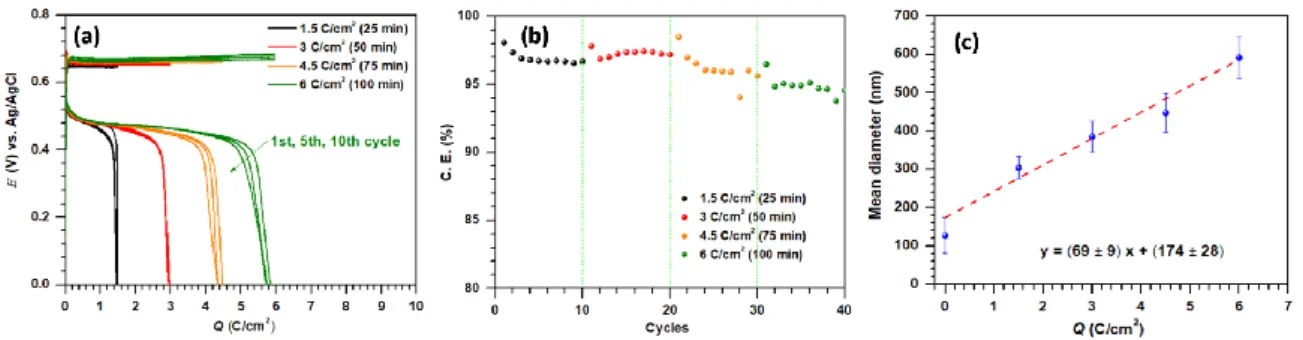
The second aim of this work is to switch to battery conditions and test the capability of free-standing CNFs in maintaining the full reversibility of the electrodeposition-electrodissolution at high loads (Fig. 2 (c-d) and Fig. 3). All experiments were performed in a standard 3-electrode cell for accurately monitoring the electrode potential. Free-standing CNFs were used as working electrode (area 1 cm2; thickness 150 µm, 1.54 mgCNF/cm2), and ca. 7 mL of 1 M acetate buffer containing 0.1 M Mn2+ as electrolyte (pH 5). We first performed successive galvanostatic cycles at 1 mA/cm2 by increasing progressively Qcharge from 1.5 to 6 C/cm2 (i.e., 0.52 to 1.7 mA·h/cm2). Fig. 3 (a-b) shows the corresponding galvanostatic charge-discharge curves and C.E. values. Upon increasing the charging
5
time, the MnO2 deposit remains highly homogeneous while its thickness increases, as clearly evidenced by the FEG-SEM images and the estimated mean diameter of MnO2 covered CNFs (ESI Fig. S8 and Fig. 3(c), respectively). However, we notice a positive drift in the charge potential for Qcharge> 3 C/cm2 that might be indicative of small local pH or [Mn2+] gradients induced by the high loading. Besides, the C.E. value also slightly decreases, indicating a somewhat accumulation of MnO2 at the CNFs for the highest loads. Accordingly, the PAN-derived electrospun CNFs were tested for long term cycling at a Qcharge of 3 C/cm2 in the 1 M acetate buffer electrolyte pre-equilibrated with 0.1 M MnCl2. ESI Fig. S9 (a-b) shows the corresponding galvanostatic charge-discharge curves and C.E. over 100 cycles. The charge/discharge potentials remain highly constant during cycling, with a low hysteresis of 0.16 V, while the C.E. remains in the 97-98% range. We further increased the Mn2+ concentration up to 0.15 M and successfully cycled CNFs over 300 cycles at Qcharge of 5 C/cm2 (Fig. 2(c-d)). The potential remains again highly stable during the charge, indicative of negligible local pH or [Mn2+] gradients, with low hysteresis (0.16 V). The C.E. remains in the 95-98% range over the 300 cycles performed; lowered by 2-5% only in comparison to those observed during in-situ EQCM cycling (180 mC/cm2) (Fig. 2(d)). Based on 1.7 e- reversibly exchanged, the mass of MnO2 electrodeposited during Qcharge of 5 C/cm2 is estimated to be 2.6 mgMnO2/cm2, which corresponds to a high mMnO2/mcarbon ratio of 1.7 or 63% of the active material in the charged electrode (see Table 1).
Fig. 3 Galvanostatic measurements performed using free-standing 3D CNF electrodes at ±1 mA/cm2. (a-b) Qcharge increased progressively from 1.5 to 6 C/cm2 and corresponding C.E. (c) Variation of the mean diameter of CNFs as a function of applied loads after electrodeposition of MnO2 at 1 mA/cm2 (see more details in ESI Fig. S8). The red line is the linear regression (the equation of which is shown on the graph) to the experimental data with r2 = 0.935.
The gravimetric capacity of the cathode is thus as high as 338 mA·h/gMnO2+CNF (equivalent to 534 mA·h/gMnO2). By using CNFs, we thus significantly improved the mMnO2/mcarbon ratio and so areal/gravimetric capacity as compared to the early work performed by Mateos et al.15 on model GLAD-ITO electrodes in the same buffered aqueous electrolyte (Table 1). The present results also compare favorably with those reported up-to-date for MnO2-cathodes based on commercial carbon/graphite felts (cloths) and operating through a similar conversion mechanism (see Table 1 for selected data from publications providing detailed information on the commercial carbon substrate). Upon utilization of carbon cloth/felts with fiber diameter 8-10 µm as substrates for electrodeposition of MnO2, low relative MnO2 loadings (< 30%) were previously systematically retrieved, therefore leading to limited gravimetric capacities (< 150 mA·h/gMnO2+substrate) when considering the full mass of the cathode. The much better gravimetric capacity achieved here at the electrospun CNFs can be attributed to the higher aspect ratio of this electrode as compared to commercial fibers. The typical Brunauer-Emmett-Teller (BET) specific surface area of pristine carbon/graphite felts (cloths) with 8–10 μm sized fibers remains below 3 m2/g,30-33 whereas the typical BET surface area of non-porous PAN-derived CNFs are 35 m2/g, thus one order of magnitude higher. It is worth noting here that the gravimetric capacity retrieved in the present work also outperforms those previously reported in mild acidic aqueous electrolytes for composite slurry electrodes made of MnO2 active material (generally 70% in mass) combined with carbon and polymer additives. Indeed, the record gravimetric capacity of 382 mA·h/gMnO2 reported in the literature translates into < 270 mA·h/gMnO2+additives.34 Upon decreasing the proportion of additives to 10% (only carbon), Gao et al. were able to achieve a high gravimetric capacity of 330 mA·h/gMnO2+carbon but at the expense of a low cyclability (-30% after 5 cycles).35
Finally, galvanostatic cycling in Zn/CNF-MnO2 cell configuration was performed at ± 1 mA/cm2 for
Qcharge = 5 C/cm2 (or 1.39 mA·h/cm2) using aqueous 0.15 M Mn2+ + 0.25 M Zn2+ (chloride) + 1 M acetate buffer (pH = 4.85) solution as electrolyte, CNFs as working electrode and Zn foil as counter electrode. The collected GCDs and corresponding C.E. over 100 cycles are shown in EIS Fig. S10 (a-b). The charge
6
and discharge potentials at an average value of 1.71 V and 1.55 V, respectively, remain remarkably highly stable during cycling with a low hysteresis of 0.16 V, similar to the one observed in a 3-electrode cell. This is because Zn anode is highly stable in near-neutral acetate-based aqueous electrolytes as reported previously.28 The observed gravimetric capacity of the cathode in the 2-electrode cell configuration is as high as 309 mA·h/gMnO2+CNF while maintaining a high mMnO2/mCNF ratio of 1.48, considering the identical Mn4+(s)↔Mn2+(aq) conversion reactions involved on the cathode side. The C.E. during GCD cycling remains ≥ 96.6% over 100 cycles.
In conclusion, reversible electrodeposition-electrodissolution of MnO2 in a mild aqueous buffered electrolyte (pH = 5) was successfully transposed from model ITO electrodes into more practical CNFs electrodes. This allowed to reversibly cycling the cathode at a high surface load (up to 1.4 mA·h/cm2) with low hysteresis and achieving the highest gravimetric capacity to date (based on the total cathode mass). The results presented here clearly show that the combination of PAN-derived electrospun CNFs with a buffered mild acidic aqueous electrolyte is a good and promising option to achieve mild aqueous batteries with high energy efficiencies. More work is going on to further improve the charge capacity as well as rate performances. High surface area PAN-derived thick and dense 3D CNF electrodes with a reduced inter-fiber spacing (voids) could help in further increasing the MnO2 loading without compromising reversibility. Optimization of the electrolyte composition might also be achieved to avoid pH and/or [Mn2+] gradients at high loads.
Acknowledgements
7
Table 1 Performance comparison of electrospun free-standing CNFs with other substrates used for
electrodeposition-electrodissolution reactions of MnO2 in mild or acidic electrolytes.
* assuming a typical density of 0.1-0.15 g/cm3 – provider website (TE.GW group)
§ calculated based on the n value and assuming an identical molecular mass of 87 g/mol for the electrodeposited MnO 2 film. #
estimated from electrode weight before/after electrodeposition $
deduced from ICP quantification Substrates Thicknes s (mm) Substrat e Mass (mg/cm2) Electrolyte Qcharge (mA·h/c m2) n mMnO2 deposite d at each cycle (mg/cm2 ) Relative MnO2 mass loading Qcharge (mA·h/gMnO2+ substrate) Ref Carbon felt 3.18 (fiber diameter 8-10 m) 24 1 M MnSO4 + 0.05 M H2SO4 1 1.9 e- 1.7§ 6.6% 39 5 Graphite felt modified with carbon black and PVDF 5 5 50-75* 52.5-77.5 0.5 M Mn(acetate)2 + 0.5 M ZnCl2 + 2 M KCl electrolyte 10 10 ns (1.7 e -assumed) 19§ 20-27% 19-26% 145-106 140-104 36 Carbon cloth 0.33 (fiber diameter 10 m) 12 1 M Zn(acetate)2 + 0.4 M Mn(acetate)2 0.5 2 1.7 e- 0.9 3.6# 7% 28% 39-128 28 GLAD-ITO 0.001 0.38 1 M acetate buffer + 0.1 M MnCl2 0.028 1.86 e- 0.048$ 11% 65 15 CNF 0.15 (fiber diameter 127 ± 47 nm) 1.51 1 M acetate buffer + 0.15 M MnCl2 1.39 1.7 e- 2.6§ 63% 338 This work CNF 0.15 (fiber diameter 127 ± 47 nm) 1.54 1 M acetate buffer + 0.1 M MnCl2 0.83 1.7 e- 1.6§ 51% 264 This work CNF/Au (in-situ EQCM) ns 0.035 1 M acetate buffer + 0.01 M MnCl2 0.05 1.7 e- 0.095§ 73% 385 This work
8
References
1 X. Liu, J. Yi, K. Wu, Y. Jiang, Y. Liu, B. Zhao, W. Li and J. Zhang, Nanotechnology, 2020, 31, 122001-122050. 2 C. M. Julien and A. Mauger, Nanomaterials, 2017, 7, 396-437.
3 Y. Zeng, X. Zhang, Y. Meng, M. Yu, J. Yi, Y. Wu, X. Lu and Y. Tong, Adv. Mater., 2017, 29, 1700274-1700280. 4 G. G. Yadav, J. W. Gallaway, D. E. Turney, M. Nyce, J. Huang, X. Wei and S. Banerjee, Nat. Commun., 2017, 8,
14424-14432.
5 W. Chen, G. Li, A. Pei, Y. Li, L. Liao, H. Wang, J. Wan, Z. Liang, G. Chen, H. Zhang, J. Wang and Y. Cui, Nat. Energy, 2018, 3, 428-435.
6 D. Chao, W. Zhou, C. Ye, Q. Zhang, Y. Chen, L. Gu, K. Davey and S. Z. Qiao, Angew. Chem. Int. Ed. Engl., 2019, 58, 7823-7828.
7 G. Fang, J. Zhou, A. Pan and S. Liang, ACS Energy Lett., 2018, 3, 2480-2501.
8 H. Pan, Y. Shao, P. Yan, Y. Cheng, K. S. Han, Z. Nie, C. Wang, J. Yang, X. Li, P. Bhattacharya, K. T. Mueller and J. Liu,
Nat. Energy, 2016, 1, 16039-16045.
9 M. J. Park, H. Yaghoobnejad Asl and A. Manthiram, ACS Energy Lett., 2020, 5, 2367-2375.
10 B. Lee, H. R. Seo, H. R. Lee, C. S. Yoon, J. H. Kim, K. Y. Chung, B. W. Cho and S. H. Oh, ChemSusChem, 2016, 9, 2948-2956.
11 J. Yang, J. Cao, Y. Peng, W. Yang, S. Barg, Z. Liu, I. A. Kinloch, M. A. Bissett and R. A. W. Dryfe, ChemSusChem, 2020,
13, 4103-4110.
12 C. F. Bischoff, O. S. Fitz, J. Burns, M. Bauer, H. Gentischer, K. P. Birke, H.-M. Henning and D. Biro, J. Electrochem.
Soc., 2020, 167, 020545-020552.
13 X. Guo, J. Zhou, C. Bai, X. Li, G. Fang and S. Liang, Mater. Today Energy, 2020, 16, 100396-100403.
14 M. Mateos, N. Makivic, Y.-S. Kim, B. Limoges and V. Balland, Adv. Energy Mater., 2020, 10, 2000332-2000343. 15 M. Mateos, K. D. Harris, B. Limoges and V. Balland, ACS Appl. Energy Mater., 2020, 3, 7610-7618.
16 M.-S. Wu, Y.-H. Ou and Y.-P. Lin, Electrochim. Acta, 2010, 55, 3240-3244. 17 A. Singh and V. Kalra, J. Mater. Chem. A, 2019, 7, 11613-11650.
18 R. Schierholz, D. Kröger, H. Weinrich, M. Gehring, H. Tempel, H. Kungl, J. Mayer and R.-A. Eichel, RSC Adv., 2019, 9, 6267-6277.
19 A. Gupta, S. R. Dhakate, P. Pal, A. Dey, P. K. Iyer and D. K. Singh, Diamond Relat. Mater., 2017, 78, 31-38. 20 D. Hussain, F. Loyal, A. Greiner and J. H. Wendorff, Polymer, 2010, 51, 3989-3997.
21 J.-K. Chang and W.-T. Tsai, J. Electrochem. Soc., 2003, 150, A1333-A1338.
22 M. Huynh, D. K. Bediako, Y. Liu and D. G. Nocera, J. Phys. Chem. C, 2014, 118, 17142-17152. 23 S. Chou, F. Cheng and J. Chen, J. Power Sources, 2006, 162, 727–734.
24 W. Huang, J. Li and Y. Xu, Materials, 2017, 10, 1205-1222.
25 B. Babakhani and D. G. Ivey, J. Power Sources, 2011, 196, 10762-10774.
26 E. S. Ilton, J. E. Post, P. J. Heaney, F. T. Ling and S. N. Kerisit, Appl. Surf. Sci., 2016, 366, 475-485. 27 J. Liu, Y. Zhang, Q. Gu, A. Sheng and B. Zhang, Minerals, 2020, 10, 690-704.
28 X. Zeng, J. Liu, J. Mao, J. Hao, Z. Wang, S. Zhou, C. D. Ling and Z. Guo, Adv. Energy Mater., 2020, 10, 1904163-1904171.
29 P. Ruetschi, J. Electrochem. Soc., 1984, 131, 2737–2744.
30 R. Wang, Y. Li and Y.-L. He, J. Mater. Chem. A, 2019, 7, 10962-10970.
31 Z. He, L. Liu, C. Gao, Z. Zhou, X. Liang, Y. Lei, Z. He and S. Liu, RSC Adv., 2013, 3, 19774-19777. 32 H. R. Jiang, W. Shyy, M. C. Wu, R. H. Zhang and T. S. Zhao, Appl. Energy, 2019, 233-234, 105-113.
33 T. H. Noh, M. Y. Kim, D. H. Kim, S. H. Yang, J. H. Lee, H. S. Park, H. S. Noh, M. S. Lee and H. S. Kim, J. Electrochem.
Sci. Technol. , 2017, 8, 155-161.
34 B. Wu, G. Zhang, M. Yan, T. Xiong, P. He, L. He, X. Xu and L. Mai, Small, 2018, 14, 1703850-1703857.
35 X. Gao, H. Wu, W. Li, Y. Tian, Y. Zhang, H. Wu, L. Yang, G. Zou, H. Hou and X. Ji, Small, 2020, 16, 1905842-1905851. 36 C. Xie, T. Li, C. Deng, Y. Song, H. Zhang and X. Li, Energy Environ. Sci., 2020, 13, 135-143.