HAL Id: insu-02270096
https://hal-insu.archives-ouvertes.fr/insu-02270096
Submitted on 23 Aug 2019HAL is a multi-disciplinary open access
archive for the deposit and dissemination of sci-entific research documents, whether they are pub-lished or not. The documents may come from teaching and research institutions in France or abroad, or from public or private research centers.
L’archive ouverte pluridisciplinaire HAL, est destinée au dépôt et à la diffusion de documents scientifiques de niveau recherche, publiés ou non, émanant des établissements d’enseignement et de recherche français ou étrangers, des laboratoires publics ou privés.
Using AADL to build critical real-time systems:
Experiments in the IST-ASSERT project
J Hugues, Laurent Pautet, B Zalila, P Dissaux, M Perrotin
To cite this version:
J Hugues, Laurent Pautet, B Zalila, P Dissaux, M Perrotin. Using AADL to build critical real-time systems: Experiments in the IST-ASSERT project. Embedded Real Time Software and Systems (ERTS2008), Jan 2008, toulouse, France. �insu-02270096�
Using AADL to build critical real-time systems:
Experiments in the IST-ASSERT project
J. Hugues
1, L. Pautet
1, B. Zalila
1,P. Dissaux
2, M. Perrotin
3 1: GET-Telecom Paris, UMR 5141 CNRS, 46, rue Barrault – 75013 Paris, France2: Ellidiss Technologies, 24, quai de la douane, 29200 Brest, France 3: European Space Agency, Keplerlaan 1 - 2201 AZ Noordwijk - The Netherlands
Abstract: In this paper, we discuss the use of the AADL
(Architecture Analysis and Design Language) in the IST-ASSERT project, which spans from 2004 to 2007. In the context of this project, the European Space Agency, in collaboration with tool providers and academic partners explored the use of AADL to build space systems. At the completion of the project, we provide our report and experiments on AADL for building critical systems.
Keywords: IST-ASSERT, AADL, MDD, Stood,
Ocarina.
1. Introduction
Building Distributed Real-Time Embedded systems requires a stringent methodology. We note there is a strong link between the requirements and the final implementation (e.g. scheduling, resource dimensioning). Modeling, formal verification and code generation are state-of-the-art solutions to discuss requirements, validate and implement a design.
The IST-ASSERT project, part of the 6th framework program of the European Commission aimed at providing tools, methods and runtime environments to ease the development of space critical systems. This project began in 2004, and will see its conclusion in January 2008. This project involved 30 partners from both the industrial and academic domain, for an overall budget of 15MEUR. At the completion of the project, we draw some conclusions on the outcome of this project.
Being an integrated project, ASSERT explored many trends and solutions. There is not one common result in the project, but instead a full range of solutions for different steps in the engineering of complex systems. In the remainder of this paper, we focus on the AADL related results of this project. The SAE AADL language was a novel aspect of ASSERT. After is standardization in 2004, AADL has been highly assessed by ASSERT partners. Constructive feedback has been provided to serve as “lessons learned” for defining AADLv2.
In the next sections, we present the ASSERT project, and more specifically the ASSERT process for building space applications. We then present the incarnation of this process using AADL as a backbone to model applications.
We finally describe a case study based on the integration of SCADE and SDL models. We show how an integrated tool-suite based on AADL allows complete code generation from high-level models to high-quality code, conformant with ESA standards.
2. The ASSERT Project
The ASSERT Project (Automated proof-based System and Software Engineering for Real-Time systems) is an integrated project partially funded by the European Commission within the Information Society Technologies priority of the 6th Framework Programme in the area embedded systems.
The project is coordinated by the European Space Agency (ESA), and is a consortium made of 28 partners representing the space industry, research laboratories, software houses and tool developers. The project started in September 2004 and ended in January 2008.
The main objective of ASSERT is to change the way system and software engineering is performed today to adopt a more reliable and scientific approach based on modeling, preservation of system properties and model transformation down to the final code.
The current results include a process, a set of tool prototypes and case studies demonstrating the validity of the overall approach. The figure 1 recaps the main logic of the ASSERT process.
The process consists in three phases:
• A modeling phase, where the developer captures the functional and non functional properties of his system,
• A model transformation and verification phase, which automatically verifies the feasibility of the system,
• An automatic code generation phase which produces a distributed real-time software system that is ready for download on hardware target.
Capture of the hardware architecture Capture of the Modeling phase system properties c Capture of the Capture of the
Modeling phase hardware architecture
system properties c System real-time architecture d Model transformation System real-time architecture System real-time architecture d e Model transformation Feasibility analysis Complete system Real-time operating system f Automatic code generation Complete system Real-time operating system f Automatic code generation
Figure 1 ASSERT Process
One of the main characteristics of this process is that, except in the first phase, it is fully automated, This means that apart from a set of models, no human intervention is required to generate a complete software system made of physically distributed nodes, and possibly developed using heterogeneous modeling languages and tools. The “zero manual-coding” approach has been in the heart of the whole ASSERT logic and has driven the development of innovative technologies and tools that until now only existed as theoretical concepts.
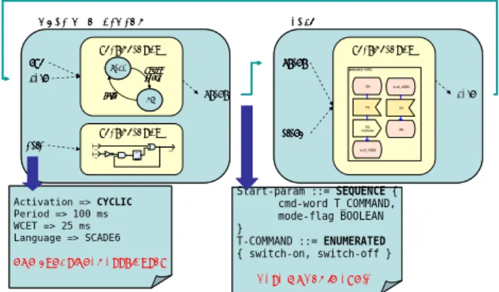
To support this approach, two pillars have been built, that we have called the Interface view and the Data view. The objective behind these views is to capture as much “implementation-neutral” information about the system as possible, without constraining the user to select one particular development environment for describing the behavior of his system. The Interface view helps the user capture his system structure, identify functional blocks, and set non-functional attributes to interfaces. Example of such attribute can be a period for activating a function (see figure 2).
The Data view, on the other hand, contains the description of all the messages that are exchanged between functional blocks, in an implementation language-neutral representation. We use for this description the ASN.1 notation that gives enough expressive power to represent complex data types together with means to automatically generate binary encoders and decoders at code level. The functional blocks themselves can be implemented in virtually any modeling language; provided that a tool exists that can generate code for the behavior of the block. This is where the tools develop in ASSERT enter the
game: by reading the Interface and Data view, they will detect that a given (known) code generator is used and automatically generate wrappers (that we call containers) to make a link between the functional code and the run-time environment to send and receive messages.
MODE MANAGEMENT > run > fdir > calc Functional view Functional view FBY 1false stop status start safe op go_op/ start fdir safe op go_op/ start fdir start> FDIR > start > alarm Functional view > fdir proce s s A BB1 idle PI1 RI1 (myData) w ait_A BB2 w ait_A BB2 PI2 idle MODE MANAGEMENT > run > run > fdir > fdir > calc > calc Functional view Functional view FBY 1false stop status start safe op go_op/ start fdir safe op go_op/ start fdir start> FDIR > start > start > alarm > alarm Functional view > fdir proce s s A BB1 idle PI1 RI1 (myData) w ait_A BB2 w ait_A BB2 PI2 idle Start-param ::= SEQUENCE { cmd-word T_COMMAND, mode-flag BOOLEAN } T-COMMAND ::= ENUMERATED { switch-on, switch-off }
DATA MODEL IN ASN.1
Start-param ::= SEQUENCE { cmd-word T_COMMAND, mode-flag BOOLEAN } T-COMMAND ::= ENUMERATED { switch-on, switch-off }
DATA MODEL IN ASN.1
Activation => CYCLIC Period => 100 ms WCET => 25 ms Language => SCADE6 NON-FUNCTIONAL ATTRIBUTES Activation => CYCLIC Period => 100 ms WCET => 25 ms Language => SCADE6 NON-FUNCTIONAL ATTRIBUTES
Figure 2 Modeling an application
When it is appropriate, the contents of data structures are automatically marshaled in a compact binary format before being transmitted to a network. This mechanism, that is added automatically, is required when sending data in an heterogeneous environment, or when the bandwidth of a bus is too limited to simply send a memory dump. ASN.1 tools are used for the encoding and decoding phases. When not needed, of course, the encoding functions are not used.
The ASSERT technology can be adapted to any existing modeling framework and associated code generator (so far ObjectGeode SDL, SCADE, Simulink and Rhapsody are supported) to build the functional parts.
The last “brick” of the ASSERT toolset is the virtual machine (VM). This essential element is made of a real-time and distributed operating system that is able to ensure the preservation of the non-functional properties expressed in the Interface view.
3. The “AADL” track
The ASSERT development process is composed of a set of modeling and production activities which steps can be summarized as follow:
- Data View: Definition of a set of data structures that must be expressed in ASN.1;
- Functional View: Definition of a set of applicative operations that can be implemented in various implementation or modeling languages (Ada, C, Lustre, SDL, etc.). Operation parameters must refer to data types defined in the Data View.
- Interface View: Definition of a set of interacting Application level containers (APLC). APLC interfaces must refer to operations defined in the Function View. - Concurrency View: Definition of a set of interacting Virtual Machine level containers (VMLC). VMLC model aims at being automatically deduced from the three preceding views, by applying generation rules known as “Vertical Transformations”.
The VMLC model can then be processed again, firstly by binding it onto execution platform architecture defined in a Deployment View, then by generating target language source code (i.e. Ada or C) to produce a set of executable files to be run on top of an ASSERT compliant run time executive.
The ASSERT development process has been implemented in two parallel tracks. One of them uses the HRT-UML technology, and the other one is based on the Architecture Analysis and Design Language (AADL) international standard. This latter implementation of the ASSERT process, known as the “AADL track” is presented in details in this paper.
3.1 A Quick Overview of AADL
In this section, we provide a quick overview of the AADL modeling language. AADL is a versatile modeling language that can provide a basis to model all aspects of a system.
AADL (Architecture Analysis and Design Language) [1] aims at describing DRE (Distributed Real-time Embedded) systems by assembling blocks separately developed. The AADL allows for the description of both software and hardware parts ofa system. It focuses on the definition of clear block interfaces, and separates the implementations from these interfaces. It can be expressed using both a graphicalor a textual syntax.
An AADL model can incorporate non-architectural elements: embedded or real-time characteristics of the components (execution time, memory footprint, etc.), behavioral descriptions, etc. Hence it is possible to use AADL as a backbone to describe all the aspects of a system.
An AADL description is made of components. The AADL standard defines software components (data, thread, thread group, subprogram, process), execution platform components (memory, bus, processor, device) and hybrid components (system).
Components describe well identified elements of the actual architecture.Subprogramsmodel procedures like in C or Ada.Threadsmodel the active part of anapplication (such as POSIX threads). AADL threads may have multiple operational modes. Each mode may describe a different behaviour and property values for the thread.
Processes are memory spaces that contain the threads. Thread groups are used to create a hierarchy among threads. Processors model micro-processors and a minimal operating system (mainly a scheduler). Memories model hard disks, RAMs, buses model all kinds of networks,wires,devicesmodel sensors, etc.
Unlike other components, Systems do not represent anything concrete; they actually create building blocks to help structure the description.
Component declarations have to be instantiated into subcomponents of othercomponents in order to model an architecture. At the top-level, a system contains all the component instances. Most components can have subcomponents, so that an AADL description is hierarchical. A complete AADL description must provide a top-most level system that will contain the other components, thus providing the root of the architecture tree. The architecture in itself is the instantiation of this system.
The interface of a component is calledcomponent type. It provides features (e.g. communication ports). Components communicate one with another by connecting their features. To a given component type correspond zero or several implementations. Each of them describe the internals of the components: subcomponents, connections between those subcomponents, etc. An implementation of a thread or a subprogram can specify call sequences to other subprograms, thus describing the execution flows in the architecture. Since there can be different implementations ofa given component type, it is possible to select the actual components to put into the architecture, without having to change the other components, thus providing a convenient approach to configure applications.
The AADL defines the notion of properties that can be attached to most elements (components, connections, features, etc.). Properties are attributes that specify constraints or characteristics that apply to the elements of the architecture: clockfrequency of a processor, execution time of a thread, bandwidth of a bus, etc. Some standard properties are defined; but it is possible to define one’s own properties. A more detailed introduction to the AADL can be found in [2].
3.2 Data View
Applicative data types must be specified using the specialized ASN.1 language. An utility tool provides an automatic conversion of these data type descriptions into a sequence of AADL declarations that allows for a proper reference of these data types during the other phases of the ASSERT modeling process in AADL.
References to ASN.1 data types are represented by AADL Data components types and implementations whose
specification may be located inside a separate package or copied into the others “views” that must reference them for the purpose of typing ports, subprogram parameters or shared data subcomponents.
3.3 Functional View
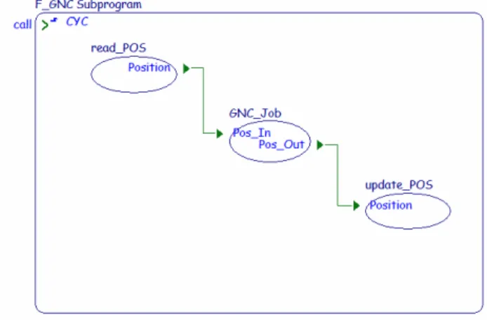
Applicative functions can be described as black boxes by AADL subprogram components. Such an AADL representation of applicative functions consists in a subprogram component type expressing a typed parameter list if any, and a subprogram component implementation providing necessary details about the actual implementation language, the name of the corresponding piece of code in the source files and the functional dependencies (required remote functions).
Additional information such as worst case execution time can also be handled by appropriate AADL properties to allow for various checks (schedulability, dependability, etc.). The set of AADL subprogram components that form the “Function View” can be grouped inside a separate package or directly included inside the other “views” that reference it. The picture below represents a functional view, with a set of cascaded calls.
Figure 3 Functional View in AADL
3.4 Interface View
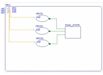
This view is the only one of the overall ASSERT process, that required some semantic add-ons to the standard AADL definitions. The “Interface View” can be expressed by a set of interacting AADL system components whose interfaces contain respectively in and out event ports, representing provided and required services.
Interfaces define interactions between the components. To bring precise hard real time semantics, the ASSERT project restricted the semantics of the interactions to the one amenable to verification. ASSERT retained the Ravenscar Profile[6], defined in the context of the Ada language. This profile defines a subset of concurrent interactions that can be fully analyzed.
The Ravenscar profile can be adapted to other semantics, and formed the root of the computational model supported by the interface view: the Ravenscar Computational Model. The precise RCM semantics is brought by a few specific AADL properties that have been invented for that purpose and are specified within the ASSERT property set: a few properties have been defined to represent cyclic (CYC), sporadic (SPO) or protected activities (PRO). The components defined in this view are called Application-Level Components (APLCs).
Figure 4 Interface View in AADL
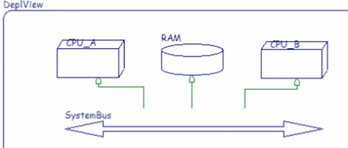
3.5 Deployment View
The description of the execution platform and the allocation of the software entities onto it can be performed in standard AADL. In an AADL operational system, computing hardware is represented by a set of processor and memory components, whereas executable software is composed of a set of threads within a process. Binding properties allows for proper allocation of threads to processors and processes to memories.
3.6 Concurrency View
The Interface View defines a high-level abstraction of the model, made of APLCs. To go downwards to fully executable system, we map this interface view, made of cyclic, sporadic or protected activities onto AADL components that actually perform such actions, namely threads and data components. These components are referred to as VM-level containers.
The full definition of a software architecture in terms of ASSERT run-time compliant entities (VMLCs) could be directly performed in AADL, by specifying a set of interacting threads and shared data within processes. However, one of the goals of the ASSERT development process consists in enforcing automatic construction of the concurrent software architecture from the previous modeling views of the application. Such a generation of
the “Concurrency View” from the other views is known as the “Vertical Transformations”.
By mapping the interface view (an ASSERT-specific model) onto the concurrency view, we retrieve the benefits of a fully standardized model that can be analyzed using AADL compliant tools.
3.7 Code Generation
Concurrency, Deployment and Data views are three complementary AADL models that define orthogonal aspects of a system. By combining these three models, the user has a full view on his system.
Each AADL model is completed with supporting code; e.g. functional views come with SDL or SCADE models and associated C code, Data views come with ASN.1 models and ASN.1 C marshalling code. From the concurrency view, one can derive a set of concurrency constructs that will animate these codes.
We developed the Ocarina toolsuite as a “compiler for the AADL”. Ocarina maps AADL constructs onto a runtime that supports the semantics of AADL. We also devised PolyORB-HI, a runtime that supports both AADL and Ravenscar, written in Ada2005.
Ocarina maps the various components of the AADL model onto corresponding pieces of code. It supports both local and distributed interactions. To do so, it fully exploits information from each view to build concurrent entities that will animate the model:
• Data view: it defines type exchanges, so it is used to produce ASN.1 marshallers. One can also deduce an upper bound on the memory required to exchange information;
• Interface view: it defines signatures of the functional blocks, from which one can deduce stub/skels (a la CORBA) to send/receive requests and process them on each node;
• Concurrency view: it provides definition of computational resources (threads, mutexes, etc.) required to support the semantics of this system. • Deployment view: it defines the position of the
different entities, and the communication path between them. It is used to configure the different naming tables within the system.
By exploiting these different views, Ocarina generates Ada code that is fully compliant with both the Ravenscar profile, the restrictions defined by ESA for on-board space systems; and reflects the execution profile defined in the system.
4. Tool support
The ASSERT “AADL track” is supported by a tool-chain prototype that is composed of the following elements:
• ASN.1 to AADL conversion tool, a C framework and associated code generator to build ASN.1 marshallers developed on purpose by Semantix; • Stood AADL modeling tool, and vertical
transformation engines developed by Ellidiss [4]; • Ocarina AADL code generator and associated
runtime developed by ENST University [5]. One of the advantages of using the AADL track for supporting the ASSERT process is that it is possible to express the various modeling views in a textual way, by the mean of a simple editor.
However, in order to enforce the guided modeling process that is promoted by ASSERT, a prototype customization of the Stood graphical AADL tool has been performed during the project to support the Data, Function, Interface, and Deployment Views, as well as the Vertical Transformations. The following chapters show how these various modeling steps are currently supported by Stood.
5. Evaluation
To assess the AADL track, we have worked on a system based on a real industrial case-study. This case study comprises behavioural models developed in specialized languages: SDL for state machines and SCADE for dedicated computation of algorithms. The idea behind this choice was to demonstrate how the ASSERT process could handle a development where independent teams work separately and develop sub-systems using the most appropriate language.
5.1 Case study
This case study is representative of real system development, in particular in the space domain where industries are spread all over Europe, and where communication between teams is hard to manage.
In that context, it is frequent that incompatible interfaces are discovered at integration time only. The cost for updating pieces of software and validating the global consistency of these systems is therefore high.
In our case study, we have specified, at system level, a set of functional blocks communicating together and put a high effort in describing the precise data model in ASN.1. This data model contains about 70 complex data types that are used to describe messages between the state machines and data to feed the calculation functions.
The system is a real-time system that has the following cyclic behaviour:
• At each cycle one function reads some sensors and make calculation to estimate the position of the spacecraft and send data to Earth,
• One cycle out of five, another function is triggered by the first one to calculate some actuators output sent back to the first function; the time of this calculation is unknown (it is not a synchronous, blocking call);
• The cyclic function continues being activated and making some calculation waiting for the answer of the second one; once it gets it, it sends the results to control the actuators.
We consider this system as distributed: the first (cyclic) function is on one processor, and the second one on another processor. Each physical node contains a complex state machine and several calculation functions that work on their own static data. Some of these functions are therefore protected and are purposively developed by independent teams.
The main non-functional property we require in the virtual machine is to guarantee an end-to-end reactivity between the reading of the sensors and the action on the actuators. In the scope of this paper we do not enter into the details on this aspect since what we want to show here is how the use of AADL to describe the system concretely help software engineers to build their system without writing any line of manual code, in particular to make the data structure conversions and link with the virtual machine.
5.2 Building system’s views
To build this system, we first devised the Data view of the system: an ASN.1 model of the different data types to be exchanged by the different functions to represent states. From this ASN.1 model, ASN.1 tools produce an AADL model that references these types, and a set of C functions for the corresponding marshallers .
Then, we defined the Functional view of the system. For each automaton, we defined a SDL model to represent the behaviour of the system. For each computation function, a SCADE model is built. From these models, we also produced automatically a set of AADL models, and generated code using vendor-provided code generator. The next step is to produce the Interface view, representing the interaction between the different blocks: the SDL models are embodied by sporadic containers,
each port of the SDL model is mapped onto a port of this container. SCADE models are passive subprograms called by the sporadic containers. Cyclic activation (“clock” signal) is performed by a cyclic container.
The figure 3 shows an example of an APLC with sporadic activation of its interface. The figure is followed by the corresponding AADL textual specification where the ASSERT specific properties have been highlighted.
Figure 3: Sporadic activation in AADL SYSTEM APLC
FEATURES
op1 : IN EVENT PORT
{ Compute_Entrypoint => "OPCS1"; Assert_Properties::RCMoperation => SUBPROGRAM OPCS1; Assert_Properties::RCMoperationKind => sporadic; Assert_Properties::RCMPeriod => 100 ms; };
op2 : IN EVENT PORT
{ Compute_Entrypoint => "OPCS2"; Assert_Properties::RCMoperation
=> SUBPROGRAM OPCS2;
Assert_Properties::RCMoperationKind => variator; };
op3 : IN EVENT PORT
{ Compute_Entrypoint => "OPCS3"; Assert_Properties::RCMoperation => SUBPROGRAM OPCS3; Assert_Properties::RCMoperationKind => variator; }; END APLC;
SYSTEM IMPLEMENTATION APLC.others SUBCOMPONENTS
FS : DATA FUNC_STATE; PROPERTIES
Assert_Properties::RCMoperationWorksOn => REFERENCE FS APPLIES TO op1; Assert_Properties::RCMoperationWorksOn
=> REFERENCE FS APPLIES TO op2; Assert_Properties::RCMoperationWorksOn
=> REFERENCE FS APPLIES TO op3; END APLC.others;
Finally, the Deployment view is built to define the mapping of functions onto computational resources.
Figure 5: AADL Deployment View with Stood
Let us note these different models can be built by different teams, independently and then gathered to form the complete system.
Tools play a big role for the system designer. One can use the most adequate tool for these different steps, e.g. ObjectGeode, SCADE Studio, ASN.1 editors for Data and Functional Views. The Interface and Deployment views require either a simple textual editor, or an AADL CASE tool like STOOD.
The genericity of the ASSERT process also comes from the capability to let the designer use the most adequate tools for its current task. Versatility of AADL helps combining models in an easy way.
5.3 Weaving views
The Interface view is an abstraction to ease the modelling of the system, but it remains non-standard. The first automated step is to map this view onto the concurrenct view, that is plain AADL.
This step is supported by STOOD. STOOD supports a full model-to-model transformation engine, built around declarative rules. These rules are exercised on the system until the model does not evolve anymore. Each rule maps one high-level constructs (cyclic container, protected activity), onto a lower-level AADL equivalent one (AADL thread, data component).
Data, Functional, Concurrency and Deployment views denote orthogonal models that can be combined to form the system. To each element of this models, a piece of code can be attached (ASN.1 C marshaller, SCADE node, concurrent Ada code).
Ocarina exploits these different views to deduce the exact set of threads, buffers required to animate the model. Furthermore, it produces the naming table, stubs and skeletons to support interactions among nodes.
The next step is to use an orchestration builder script so that the different pieces of code are woven together to form the final application. Defining such script is highly technical: it involves understanding precisely how the each code generator produces code so that one can “plug” other code, e.g. calling SCADE code from a SDL model; triggering a SDL port. By defining a complete process, the system designer only needs to focus on its own set of models: Data, Functional and Interface views. From these models, a complete automated process handles code generation.
Current tool support allows one to process this case study, leading to a full running example.
5.4 Running the system
The different tools generate either portable C or Ada code. We compile the system on native platforms, or embedded one. ASSERT partners defined an Ada compiler for the LEON2 processor. This processor has been selected by ESA for its next generation platforms. Final executable runs well on either the tsim LEON simulator, or Gaisler’s RASTAN boards, meeting all resource requirements. However, it will be optimized in next iterations of ASSERT.
Let us note this case study was performed without writing a single line of code; focusing on the models and moving directly to executable system is a key achievement of the ASSERT project. This achievement had to be validated by industrial partners to strengthen ASSERT achievements, with actual systems run on their own development boards. Other case studies, proposed and performed by ASSERT industrial partners demonstrated the same level of achievement.
6. Lessons Learned
During this exercise, we have been able to assess the suitability of AADL to capture a system’s structure, interfaces, and non-functional attributes, in order to “implement” the assert process.
Given the initial requirements from the project, it was first not possible to directly map all the project’s “entities” to AADL constructs. In general, the first evaluations showed that AADL was more suitable to express physical system architectures rather than more abstract logical architecture (independent from implementation), and this first glance led to discard AADL as the main system language by some assert partners, in favour of a UML profile.
But it quickly appeared that AADL had also unique strengths and potential that UML could not compete with (such as being an unambiguous textual language, as opposed to an informal graphical notation with “fuzzy” semantics). If data types are not well supported in AADL,
it was possible to build an elegant way to make a link with another textual-friendly notation (ASN.1). Such flexibility allowed us to quickly build tools around AADL to connect AADL partial models to other modelling tools (so far, we tested ASN.1, SCADE, SDL).
Besides, AADL appeared to be a very flexible language that goes further than most conventional modelling tools thanks for example to the extensible properties mechanisms. Here, there is no complex “stereotypes” and “tags” expressed as extensions of a meta-model, but simple property sets that allow us to combine the use of ASSERT-specific system attributes with standard, off-the-shelves AADL tools. Such property sets are defined as plain-text for easier adaptation. Tool support can then simply parse these new property sets to add new capabilities.
Let us note also that the graphical AADL notation, supported by the STOOD tool, is used by ESA as a complement to the textual notation to give a higher-level view of the model when required.
In the future it is planned to improve the graphical AADL notation and CASE tool to provide a more integrated toolset and guide the user through all the steps of the process. At the moment, the automated part concerns the code generation, once all the models are ready.
Current tools do not help much yet on the best ways to build these models: how to capture the system architecture, defining the semantics of these attributes, the best step in the process to set them, how to select the most appropriate language to model the system behaviour, etc. Such extension to build “wizards” is certainly an important challenge for future industrial projects.
7. Conclusion
In this paper, we showed the main achievements performed within the scope of the ASSERT project. The ASSERT project focuses on the definition of an integrated process to build ESA next generation mission – critical systems. By focusing on model-driven engineering, we aimed at exploiting state of the art software engineering process.
ASSERT defines a generic process, where one defines high-level components (APLCs), data types and functional models (expressed using industry-strength tools like SDL, SCADE …). By mapping these different models onto an AADL model, we showed how to combine these complementary views to build a full executable model of the system, expressed in standard AADL 1.0; and then to generate code from it. Generated code combines code from different origins; AADL, SDL,
SCADE, ASN.1 code generator’s output is orchestrated to produce one full executable.
We validate this approach on industrial case studies provided by ESA. Such evaluation demonstrated the pertinence of the approach. Code quality is satisfactory, model are built in full compliance with the ASSERT process and is partially automated from model to code. Future work, to be carried out in further projects, will contemplate defining tools to help building models. This is a strong industrial challenge for complex critical systems.
8. Acknowledgement
This work has been funded in part by the IST Program of the European Commission under project IST-004033 (ASSERT). The authors thank the different partners of this project for their valuable feedbacks when defining the ASSERT process.
9. References
[1] SAE: “Architecture Analysis & Design Language (AS5506)”, available at http://ww.sae.org, 2004 [2] Feiler, P. H., Gluch D. P. and Hudak J.J : "The
Architecture Analysis & Design Language (AADL): An Introduction ", Tech. rep. CMU/SEI-2006-TN-011, 2006
[3] ISO/IEC 8652:2007: “Annotated Ada 2005 Language Reference Manual”, 2007
[4] Ellidiss-Software: “STOOD”, available at
http://www.ellidiss.com/stood.shtm, 2007
[5] ENST: “Ocarina”, available at
http://aadl.enst.fr/ocarina, 2007
[6] Brian Dobbing, Tullio Vardenega and Alan Burns. Guide for the use of the Ada Ravenscar Profile in high integrity systems. January 2003.