Development of Novel Haptic Tools for Virtual Navigation
by
Diana Sim
B.S., Engineering as recommended by the Department of Mechanical Engineering Massachusetts Institute of Technology, 2007
Submitted to the Department of Mechanical Engineering in Partial Fulfillment of the Requirements for the Degree of
Master of Science in Mechanical Engineering at the
MASSACHUSETTS INSTITUTE OF TECHNOLOGY
June 2013
ARCHNVES
4ASSACHUS M.,~ A~s S TMAE
'L 0 E
F
-@ 2013 Massachusetts Institute of Technology All rights reserved.
Signature of Author:
Certified by:
Department ofMehianical Engineering June 1, 2013
Dr. Mandayam A. Srinivasan Senior Research Scientist, Mechanical Engineering Thesis Supervisor
Accepted by:
, David E. Hardt Professor of Mechanical Engineering Chairman, Department Committee for Graduate Students
Development of Novel Haptic Tools for Virtual Navigation
by
Diana Sim
Submitted to the Department of Mechanical Engineering on June 1, 2013 in Partial Fulfillment of the Requirements for the Degree of
Master of Science in Mechanical Engineering
ABSTRACT
Learning how to navigate a real space using haptic virtual environments can be challenging. One major issue is the inefficient rate of exploration due to the single point interface of haptic devices. The use of haptic fields such as repulsive and attractive force fields was studied to determine their ability to enable global sensing to improve
haptic navigation.
Repulsive Force Fields for Global Haptic Sensing
Repulsive force fields were designed to help users understand their
environments more quickly through global sensing. Two experiments were conducted using repulsive force fields to provide information about indoor and outdoor spaces. In both experiments, repulsive force fields were found to be usable but not more effective in teaching the user about the environment than no force field.
Attractive Force Fields for Global Haptic Sensing Applied to Route Guidance
Attractive force fields were studied in the context of providing route guidance. Several haptic guides were designed and evaluated in a developmental experiment. The most promising haptic guide was selected and compared to conventional
alternatives (using no guide and an audio guide) in a main experiment to determine its ability to effectively aid route learning. The haptic guide fared poorly in the initial main experiment and was re-designed. Following this, a final main experiment was conducted with ten subjects. The results suggest that the haptic guide is, in fact, an effective tool for route learning.
TABLE OF CONTENTS
1
In tro d u c tio n ... 71.1 Motivation for BlindAid ... 7
1.2 Motivation for Thesis... 8
1.3 Overview of Thesis ... 8
2 B a c kg ro u n d ... 1 1 2.1 Needs of People W ho Are Blind...11
2.2 Tools for Blind Navigation ... 11
2.2.1 Obstacle detection ... 12
2 .2 .2 N a v ig a tio n ... 12
2.3 Haptic-Aural Virtual Navigation Planning Systems ... 14
2 .4 B lin d A id ... 1 5 3 General Methods ... 18
3.1 Subject Selection ... 20
4 Repulsive Force Fields for Global Haptic Sensing... 21
4 .1 D e s ig n ... 2 1 4.2 Implementation ... 22
4.2.1 Repulsive Force Algorithm ... 23
4.2.2 Force Point Algorithm ... 23
4.3 Experiment #1: Force Fields in Enclosed Spaces ... 24
4 .3 .1 M e th o d s ... 2 5 4.3.2 Results / Discussion ... 29
4.4 Experiment #2: Force Fields in Open Spaces ... 30
4 .4 .1 M e th o d s ... 3 0 4.4.2 Results / Discussion ... 33
5 Attractive Force Fields for Global Haptic Sensing Applied to Route Guidance ... 36
5 .1 In itia l D e s ig n ... 3 7 5.1.1 Haptic Guide Components... 37
5.1.2 Selection of Candidate Haptic Guides... 38
5.2 Initial Implementation ... 39
5 .2 .1 G u id e L in e ... 3 9 5.2.2 Tether to Last Touched Point... 40
5.2.3 Manual Forward Force... 41
5.2.4 Automatic Forward Force... 41
5.3.2 Results / Discussion ... 46
5.4 Audio Route Guide Development... 48
5.4.1 Manual Audio Guide ... 49
5.4.2 Manual Spatialized Audio Guide ... 49
5.4.3 Autom atic Audio Guide ... 50
5.4.4 Landm arks Guide ... 50
5.5 Audio Route Guidance Experiment ... 50
5.5.1 Methods...51
5.5.2 Results / Discussion ... 53
5.6 Main Haptic Route Guidance Experiment - Initial... 54
5.6.1 Methods...55
5.6.2 Results / Discussion ... 58
5.6.3 Revised Haptic Guide Design/Implementation ... 60
5.7 Main Haptic Route Guidance Experiment - Final... 61
5.7.1 Subjects...61
5.7.2 Results / Discussion ... 62
5.7.3 Outlier Analysis... 64
5.7.4 Discussion of Learning Curve ... 65
5.7.5 Discussion of Performance Based on Preference ... 66
5.7.6 Discussion of Subject Com mentary ... 67
6 Conclusions ... 72
References ... 75
Appendix A: Program Code... 80
A.1 Note about Program Code Illustrations ... 80
A.2 Com m unicating with the Phantom ... 80
A.3 Force Field Program Code ... 80
A.4 Haptic Guide Program Code... 85
A.5 Audio Guide Program Code... 89
Appendix B: Experimental Data ... 92
B.1 Force Field Experiment #1 Data ... 92
B.2 Force Field Experiment #2 Data ... 93
B.3 Haptic Guide Experiment Data ... 95
B.4 Audio Guide Experiment Data ... 96
B.5 Initial Main Experiment Data ... 97
1
INTRODUCTION
The over-encompassing goal of our research and BlindAid is to give blind people tools to build cognitive maps of unknown spaces to support independent travel. BlindAid is a haptic-aural virtual environment (VE) system that enables blind people to learn about new environments through touch and sound. Haptics refers to the study of sensing and manipulation through touch. BlindAid uses a state-of-the-art haptic device called the Phantom (Sensable). The Phantom is a desktop device that allows for virtual exploration through a stylus; this mode of exploration can be compared to exploring the world with the tip of a miniature white cane. Unfortunately, learning spaces through a single-point interface can be challenging. The goal of this thesis was to develop tools to improve haptic exploration of virtual spaces. The development process included
proposing various concepts, using design criteria to narrow down the ideas, building program code for the most promising concepts using C++, and performing experiments with human subjects to test usability.
1.1 MOTIVATION FOR BLINDAID
The ability to travel freely is a critical component of personal independence (Passini, Dupre, & Langlois, 1986). This ability is significantly compromised without vision. However, tools and strategies have been developed over the years to
compensate and provide spatial information through other means. Some commonly used tools for obstacle detection and navigation include white canes, dog guides, and
GPS (Global Positioning System) devices. However, these tools are intended for in-situ
travel, or during motion. Navigation has two major components: in-situ travel and planning. Planning which includes building cognitive maps and learning routes, is especially important without sight. Up until recently, written and verbal descriptions (Golledge, Klatsky, & Loomis, 1996) and tactile maps which are difficult to come by, were the only planning tools available to blind people (Wang, Li, Hedgpeth, & Haven,
2009). However, haptics, a relatively new area of research has introduced a new
solution, haptic virtual environment systems such as BlindAid. Studies have shown that spatial information from a virtual environment is transferable to a real environment
(Klatzky, Loomis, Beall, Chance, & Golledge, 1998; Lahav, Schloerb, Kumar, & Srinivasan, 2008; Peruch, Vercher, & Gauthier, 1995; Picard & Pry, 2009; Schmelter, Jansen-Osmann, & Heil, 2008).
1.2 MOTIVATION
Learning about an environment using a haptic map implemented by BlindAid can be more difficult than learning about a space using a visual map, because the eye can process spatial data at a much faster rate than the finger. While a sighted person can often look at a map and within seconds, understand the information being conveyed; a blind person using a single-point haptic device, might need minutes to learn the same space. This highlights the fact that vision is a global sense, allowing a person to learn in parallel, while state-of-the-art haptics is serial. Hence, there is a need to improve
BlindAid to educate users about spaces more efficiently by making haptic learning more global.
1.3 OVERVIEW
This thesis focuses on making haptic sensing with the Phantom more global to improve BlindAid. Like vision, audio is a global sense, and while we could have
explored combinations of haptics and audio to improve BlindAid, we chose to focus on haptics to avoid overloading the audio channels. Although overloading audio in a virtual system is very tempting, prior work on audio VEs suggest that conveying too much information through audio can be detrimental to learning. Furthermore, haptics is the primary mode in which users interact with the VE.
Global sensing for haptics can be implemented by creating haptic fields around objects in the environment so that the Phantom can detect them at a distance. The idea of using haptic fields to enable global haptic sensing grew out of a preliminary
experiment. In that experiment, the subject attempted to use BlindAid to learn about a VE representing a 3D cityscape with streets and buildings. The subject suggested that it
might be helpful if he could feel the locations of the buildings as he passed them while following the street. There are a number of ways to create haptic fields using repulsive
forces, attractive forces, and alternating forces. Repulsive and attractive forces can vary in different ways with respect to distance - linearly and non-linearly. Alternating forces can be dynamic, varying in time to produce a buzzing effect, or static, varying in space to create a texture which can differ in amplitude, period, and shape of waveform.
Repulsive Force Fields for Global Haptic Sensing
We decided to begin with a repulsive force field. This was a simple idea that we believed could be helpful and had received little attention from the research community. The goal was to investigate using repulsive force fields to enable global sensing to help users learn about the environment more quickly. We experimented with using repulsive force fields to provide information about indoor and outdoor spaces. Preliminary tests indicated that repulsive force fields, while not a hindrance to exploration, were not more effective in teaching the user about the environment than no force field.
Attractive Force Fields for Global Haptic Sensing Applied to Route Guidance
We then decided to explore attractive forces. However, during our research, we came up with the idea to apply attractive forces to the problem of developing a haptic guide. There is a fundamental issue with using haptics to teach routes. Simply leading a person by hand (passive exploration) does not facilitate proper route learning (Lecuyer et al., 2003; Farrell et al., 2003). Thus, we focused on using an attractive force field for global sensing, allowing users to simultaneously sense the route, while exploring surrounding objects, and applied this to developing a haptic guide. In order to facilitate active
exploration, we designed a guide that tethered users to a route to encourage navigation in the correct direction, while still allowing for the exploration of the neighboring areas. We tested a few different renditions of the haptic guide to determine whether haptics could be used for route learning. The final concept for the guide provided directions (on command) by nudging the user in the correct direction and used textures to indicate off-route areas. Ultimately, the results suggested that a haptic guide could be an effective tool for route learning.
2
BACKGROUND
2.1
NEEDS OF PEOPLE WHO ARE BLINDWhile sighted people use their eyes to gather most of the information needed to navigate, people with visual impairments are faced with significant difficulties when exploring new spaces. Passini, Dupre, & Langlois (1986) postulated that the ability to travel freely is critical to one's personal independence and integration into society. Hence, research on blindness has focused considerable energy on finding methods to improve independent navigation (Espinosa & Ochaita, 1998).
Blindness, "defined as visual acuity of less than 20/400 (6/120), or corresponding visual field loss to less than 10 degrees," ("Blindness", n.d., para. 3) and a lack of
mobility have been found to have a negative impact on different aspects of health. With regards to physical health, blindness is not only associated with lower levels of fitness in children, but also delays in the development of motor skills (O'Connell, Lieberman, &
Petersen, 2006). One study concluded that "individuals who are visually impaired have an increased risk of chronic health problems and difficulty with functional mobility tasks that require strength and speed" (Ray, Horvat, Williams, & Blasch, 2007, p. 112).
Furthermore, a lack of independence and social isolation from late-onset blindness may be associated with depression (O'Donnell, 2005). These studies stress the importance of personal independence, mobility, and their impact on quality of life.
2.2
TOOLS FOR BLIND NAVIGATIONThe most commonly used orientation and mobility tool is the white cane. A smaller percentage of people use guide dogs and GPS devices. There are
approximately 130,000 white cane users (Russell, Hendershot, LeClere, Howie, & Adler, 1997) and 7,000 dog guide users in the United States (Journal of Visual
Impairment & Blindness, 1995). Research and development of mobility tools for people who are blind typically fall into one of two categories: obstacle detection and navigation.
2.2.1 OBSTACLE DETECTION
Obstacle detection tools include the white cane, haptic or audio-enabled "augmented" white canes, guide dogs, and portable obstacle detectors ("Blindness", n.d.). Handheld obstacle detectors typically consist of acoustic or optic sensors that detect objects and convey information to the user through touch (e.g., vibration) or sound. Similar technologies have been adapted for the white cane; "augmented" white canes are designed to detect obstacles and drops offs in the environment, and
communicate through audio signals, vibrations, and/or physical forces (Borenstein, n.d.; Gallo et al., 2010; Julius, 2010; Yu, Yoon & Jeong, 2009). Mobile phones, wearable devices and robots have also been adapted to function as obstacle detectors
(Abdulrasool & Sabra, 2011; Akhter, Mirsalahuddin, Marquina, Islam, & Sareen, 2011, Pradeep, Medioni, & Weiland, 2010, Shoval, Ulrich, & Borenstein, 2003).
2.2.2 NAVIGATION
Navigational tools can be divided into two categories: in-situ tools (used during travel) and planning tools. Electronic mobility aids (EMA) like GPS devices fall under the in-situ tools category; virtual haptic systems like BlindAid and tactile maps are
considered planning tools, although tactile maps can also be mobile. In-situ Tools
Electronic mobility aids can provide information about the user's current position and instructions on how to get to a target destination (Havik, Steyvers, van der Velde, Pinkster, & Kooijman, 2010). Some of the benefits of using an EMA include "improved wayfinding performance; the detection of obstacles, objects, landmarks, and travel path alignment; and feelings of safer, more comfortable, and less stressful travel
accompanied by a higher quality and increased frequency of travel" (Roentgen, Gelderblom, Soede, & de Witte, 2009, p. 751). However, EMAs often result in slower than desired travel speeds and suffer from high rates of discontinued use (Roentgen et al., 2009).
As with obstacle detection, mobile devices such as PDAs and cell phones, and wearable devices such as vests and belts have been adapted for blind navigation (Loomis, Marston, Golledge & Klatsky, 2005; Ross & Blasch, 2000; Heuten, Henze,
Boll, & Pielot, 2008; S nchez, 2009; Seenz and Senchez, 2010). Another type of in-situ navigation aid modifies the environment to include location identifiers. Systems have used infrared transmitters, RFID (radio-frequency identification) tags, and audio
beacons in public spaces to provide information about locations or objects (Blenkhorn & Evans, 1997; D'Atri et al., 2007; Landau, Wiener, Naghshineh, & Giusti, 2005; Loomis, Golledge, Klatzky, & Marston, 2007; Na, 2006; Shiizu, Hirahara, Yanashima, &
Magatani, 2007).
Planning Tools
The traditional alternative to planning aids now being developed is to "make use of sighted assistance to describe an environment prior to visiting it, and thereby memorize a mental model to assist them when they are there on their own" (White, Fitzpatrick, & McAllister, 2008, p. 5). Planning navigation aids supply the information a person needs to create such a mental model, making them valuable for independent navigation. Tactile maps are among the most basic planning aids. Multiple studies have
demonstrated the effectiveness of tactile maps for navigation (Papadopoulos, 2004; Picard & Pry, 2009). Ungar (2000) reported two important benefits of tactile maps: in the short-term, being introduced to a space and in the long-term, improving the user's "abstract level spatial thought [by providing experience with] relating a map to the environment it represents" (p. 10). However, there are limitations; tactile maps are not widely available due to production costs, and struggle with information density - the
level of detail of a given tactile map is fixed.
Virtual environment (VE) systems have demonstrated potential as planning tools. VEs, also known as "virtual reality," are computer-simulated environments that can
model real world spaces. A major advantage of virtual environment systems, especially in comparison to tactile maps, is the ease with which maps can be reproduced and transmitted. Virtual maps can also display different amounts of detail and information
depending on zoom levels, and can relay this information dynamically. VEs are interactive: users can "explore environment[s] actively and control what they
experience" (Schmelter, Jansen-Osmann, & Heil, 2009, p. 4). In addition to serving as a general aid for experienced visually impaired travelers, haptic VE technology may be used to support an Orientation and Mobility (O&M) curriculum. Haptic technologies such
as BlindAid can help visually impaired students learn about new spaces without the aid of an instructor. This type of tool can be very valuable since instructor time is often a limiting factor. Additionally, users can interact and collect spatial information without constraints on exploration time and space, and physical effort needed. Virtual
environments can also be used for O&M diagnostic tools since they can provide efficient ways to monitor and record behavioral responses and navigation strategies of users.
A number of researchers have studied the efficacy of audio-only feedback in a
virtual environment. Such systems have utilized non-speech and speech sounds to educate the user about map objects and routes (Giudice, Bakdash, Legge, & Roy, 2010; Heuten, Henze, & Boll, 2007; Senchez, Tadres, Pascual-Leone, & Merabet, 2009; Seki & Sato, 2011). However, the audio channels can quickly become overloaded and audio alone may not be as effective as audio and haptics together; thus systems that
have both haptic and audio capabilities have received more attention.
2.3 HAPTIC-AURAL VIRTUAL NAVIGATION PLANNING SYSTEMS
Haptic-aural virtual navigation systems allow users to explore a virtual space that may model a real space, through sound and haptic stimuli, using a device like the Phantom. Researchers have conducted feasibility studies of haptic-aural navigation systems with favorable results. One such system, developed by Feintuch, Haj, & Weiss
(2006), utilizes an off-the-shelf haptic joystick and provided information about objects in 2D space via vibrations and sounds. Initial tests with blind children found that subjects
were able to translate map information gathered virtually to the navigation of real spaces. Kostopoulos, Moustakas, Tzovaras, & Nikolakis (2007) designed a method for map image analysis that could create virtual haptic-aural maps from existing map data. The system deciphered street names and conveyed location information relative to streets and intersections through audio. Kaklanis, Votis, Moschonas, & Tzovaras (2011) took virtual mapping one step further and created HaptiRiaMaps. HaptiRiaMaps is a free web-based map application that allows users to build virtual haptic-aural maps from OpenStreetMaps. In both studies, preliminary tests with blind subjects were promising.
A couple of systems have attempted to work in three-dimension. The HOMERE
haptic interactions, a virtual sun to sense cardinal direction, and spatialized ambient and event-related environmental sounds. Hara et al. (2010) explored the use of life-size virtual environments. The system consists of a white cane that can interact with virtual components and relay information audibly and tactually, an optical tracking system, and a computer to create the virtual environments. While both systems were relatively well-received, the space requirements for such devices significantly limit usability. These prior studies are important for validating the use of virtual haptic-aural maps for blind navigation, and providing insight into useful system features (many of these features are described below).
While we were unable to find any prior work related to the use of force fields to enable global haptic sensing, a few studies did explore the use of haptic guide agents.
Of note are two systems, HOMERE and the Haptic Walk-Guide simulator (HAWG). Both
systems use active guide agents which force the user to become passive in route learning. HOMERE's guide agent moves the user at a constant speed through the route from start to finish, while HAWG uses a teacher-student feature. This feature enables one haptic device to be passively led by another within the same virtual environment. The primary result of these two studies and a study on route learning via virtual environments by Farrell et al. (2003) suggests that the mode in which the space is learned is important. HOMERE users expressed a clear preference for navigation that was active and variable in route and speed, rather than passive. Farrell et al. found that active exploration resulted in more accurate cognitive maps than passive exploration. Preliminary studies illustrate some of the challenges faced by guide agents but have yet to present a good solution.
2.4 BLINDAID
BlindAid is comprised of many of the most promising tools explored, as well as a number of new ideas that have not been explored. The system allows for exploration of a virtual 3D space with spatialized sounds and contains virtual objects with varying haptic properties and surface textures (Schloerb, Lahav, Desloge, & Srinivasan, 2010). BlindAid uses headphones to convey audio and the Sensable Phantom for haptics. Users can explore the virtual space by manipulating the Phantom's stylus; the stylus
maps to a virtual object that represents the user's position in the VE called the proxy. It also incorporates other features such as haptic zooming, restarting (returns the proxy to the start position) and recording of traveled paths for instructor analysis or research purposes. The use of sounds, haptic sensations, and zooming is important in helping users learn about virtual spaces quickly. Adding tools for global sensing and route guidance may provide even more assistance in this endeavor.
Features of BlindAid
Some of the main features that have been developed and included in the BlindAid system include:
Audio
- Spatialized sound gives information that allows the user to directly perceive the
distance and direction of sound sources in the VE. Note, directional information is effectively limited to azimuth with the current system and it is difficult for the user to differentiate between sounds ahead or behind.
- Contact sounds provide information about the type of object touched by using
different identifiable short sounds (brief so as not to slow exploration).
- Identification sounds give more detail about an object than a contact sound.
Identification sounds, which are also called long sounds, are typically verbal descriptions that can be played on command when touching an object.
- Background sounds are similar to ambient noise and can give information about
a location and the boundaries of that location.
- Landmarks are useful in route planning as they can serve as audio beacons.
Landmarks are important in blind navigation so the ability to create and access landmarks in a virtual environment is essential. The audio files associated with landmarks are played using spatialized sound. This means the user hears the sound as if he/she is facing forward in the VE and the sound source is at the relative distance and direction specified.
Haptics
BlindAid uses a number of different haptic objects that can vary in color and sound. Some objects such as walls, public doors, ground textures, and rectangle objects can vary in haptic properties and texture as well. Haptic properties include
stiffness, damping, static friction, and dynamic friction as described in the OpenHaptics Toolkit API Reference Manual (Sensable Technologies, 2008). The OpenHaptics API is a C++ library that gives access to and control of the Phantom. In BlindAid, texture is achieved by applying a force tangential to the normal force of the user's hand. The texture simulates a series of individual ridges that can be varied by type (saw tooth, sinusoidal), amplitude (height), period (length), and other parameters (see Schloerb, Lahav, Desloge, & Srinivasan, 2010)). Haptic objects include:
- Walls are solid surfaces that are defined by two end points in the horizontal plane
and extend vertically from floor to ceiling. Walls have contact and long sounds.
- Public Doors are penetrable surfaces that are defined by two end points and
extend from floor to ceiling like walls. Public doors feel solid like walls until a certain threshold force is applied, at which point, the proxy passes through to the other side. The "pop-through" force is adjustable. Public doors have contact and long sounds.
- Areas are polygonal horizontal regions in the VE, extending from floor to ceiling that play background sounds when the proxy is within their boundaries. Areas can be used to represent indoor and outdoor spaces such as restaurants and parks.
- Ground Textures are polygonal floor objects that simulate textures on the floor. - Rectangle Objects are 3D rectangular prisms that are defined by two front end
points in the horizontal plane, the horizontal depth and vertical height, and the vertical coordinate of the bottom. Rectangle objects can be defined to have any
height and vertical location, as opposed to walls which extend from floor to ceiling.
3
GENERAL METHODS
Five experiments were conducted over the course of this thesis. The
experimental procedures share a number of commonalities that are explained in this section.
All experiments were conducted using version v1.50 of BlindAid with the addition
of features under test. v1.50 was adapted from an earlier version, v1.02, by upgrading the program to run under Win 7 x64, and developed using Visual Studio 2010. In addition, all experiments utilized a Desktop Phantom', which has a physical workspace of 160 W x 120 H x 120 D mm, corresponding to the region of the VE that the user explores (virtual workspace). The graphical displays shown in the map layout figures that follow correspond to the horizontal plane of the virtual workspace (top down view), such that the VE boundaries correspond to the physical W & H dimensions. The VE is measured in meters; this affects the audio since the volume and orientation of
spatialized sounds are calculated based on these units (Schloerb, Lahav, Desloge, & Srinivasan, 2010). All of the maps used for experimentation in this thesis fit in the virtual workspace and the zoom feature was not used.
The total force applied by the Phantom was capped at 0.875 N, the maximum allowable continuous force divided by a safety factor of two. During initial tests, we discovered that the Phantom would shut down after just ten minutes of use. The problem appeared to be due to software designed to protect the device from
overheating. To remedy the issue, we limited the continuous force by a safety factor of two. This extended the time before the device shut down to one to two hours. Finally, to accommodate test sessions that could last up to two hours, we swapped in a second Phantom when the first one showed signs of shutting down.
Each experiment is comprised of tasks performed in training and test settings for all conditions. All of the experimental tasks were 2D (e.g., involved a map layout that was effectively only in the horizontal plane) except for the second repulsive force field experiment. The order of trial conditions and maps were randomized in the experiment
1 The original manufacturer of the Phantom, SensAble Technologies, Inc., was recently bought by
using a pseudo-random algorithm based on the rand function in Excel. The algorithm assigned each condition (or map) a value between 0 and 1 and then sorted these assigned values in ascending order to determine the condition (or map) order. In the training trials, the subjects were asked to explore a virtual map until they had an
accurate understanding of the space as need for the particular test. Then, the subjects were tested on their knowledge of the space by performing identification tasks in which they were asked to illustrate (draw or build a physical model) or verbally identify the locations of certain objects in the VE. Alternatively or in addition, the subjects were asked to perform navigation tasks (finding their way along a specified path).
When the subject first began, the keyboard and Phantom was positioned to accommodate his/her dominant hand and overall comfort. The subject was then given a brief verbal introduction to BlindAid, the Phantom and the details of the experiment including the purpose, the design of the task (i.e. instructions), the commonalities of the test maps (i.e. controlled variables), and any other considerations for the test (i.e. aspects of the map to remember). In addition, subjects were introduced to using the Phantom and some basic features of BlindAid via a simplified map. In some
experiments, the subject was introduced to additional tools needed for the task such as a physical modeling kit.
Before each training or test trial, the experimenter identified the condition to be used (e.g., force field or no force field) and gave the subject the option to hear the instructions again. For the trainings, subjects were encouraged to take their time learning to use BlindAid and exploring the map layouts. For the tests, subjects were encouraged to complete them as quickly and accurately as possible. Once the instructions were administered, the subject was blindfolded and given the BlindAid headphones to wear.
Subject explorations of the virtual maps were recorded and saved as data files that could be replayed by the BlindAid program for later analysis. Identification tasks that did not use BlindAid (e.g., the modeling task and drawing task) were photographed for the data record. Also, the times to complete the exploration, navigation, and/or identification segments of the test were recorded. Once the subject had completed the entire experiment, he/she was asked a set of questions to better understand his/her
preferences for the conditions tested. The data is presented in graphical form in the results sections; in all graphs, a lower value corresponds to better rank/performance. The experimental procedure was approved by the MIT Committee on the Use of Humans as Experimental Subjects (COUHES).
3.1
SUBJECT SELECTIONThe subjects used in this thesis were blindfolded sighted subjects that ranged in age between 23 and 33. Blindfolded sighted subjects are believed to be sufficient for the preliminary experiments described in this thesis because these tests are intended to guide the technical development of the system. Future tests aimed at evaluating the usability of the system will be conducted with blind subjects from the ultimate user population.
4
REPULSIVE FORCE FIELDS FOR GLOBAL HAPTIC SENSING
We designed and implemented a repulsive force field to emanate from BlindAid wall objects (see Section 2.4) and conducted two developmental experiments to evaluate the effectiveness of this feature in enabling global sensing. Experiment #1 tested the repulsive force field in an enclosed space and Experiment #2 was modeled after the original cityscape VE referred to in Section 1.3.
4.1 DESIGN
The process of implementing force fields in the BlindAid software began with brainstorming strategies to identify a suitable approach. Ideas included making the repulsive force a material property of the virtual object using an OpenHaptics
parameter, HLEFFECTSPRING, and flipping the direction of the force produced. We also considered using the HLCONSTRAINT parameter that specifies an attractive force to points, lines and planes. Descriptions of HLEFFECTSPRING and
HLCONSTRAINT can be found in Addendum B-1 3 and B-1 2, respectively, of the
OpenHaptics Toolkit API Reference Manual (Sensable Technologies, 2008).
A third, more complicated approach was to do the low-level calculation of the
combined forces acting on the proxy based on the distance and direction from each object. Unfortunately, the OpenHaptics library did not allow us to adapt
HLEFFECTSPRING or HLCONSTRAINT to be used in the desired manner.
Thus, we chose to develop the third idea, employing an algorithm that loops through a set of virtual objects and calculates the component force for each. We started with a sample OpenHaptics program that modeled an attractive force between two particles; when we flipped the sign of the force, we were able to create a repulsive force. We then incorporated the repulsive force code into BlindAid through a class called vmap forcefield. This class was modeled after an existing BlindAid class
(vmaptexture) that produced textures because that class generates forces associated with the surfaces of BlindAid objects as desired for the vmap forcefield class.
and variability of the force, and deciding from which objects the force should emanate. In the case of wall objects, the algorithm needed to determine whether the proxy was in front of the wall since walls are one-sided, and if the proxy was within a pre-determined distance from the wall. Additionally, it needed to calculate the force associated with wall comers correctly.
4.2 IMPLEMENTATION
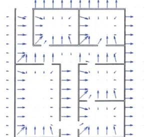
The force field feature produces a repulsive force from designated objects. In this implementation, the repulsive force fields are limited to walls and 2D (independent of the vertical axis), so force calculations are only concerned with the horizontal plane. The force (spring) constant and the radius of influence (the distance from which the force field can be felt) can be varied depending on the environment. Additionally, the
repulsive force can be toggled on and off, and the radius of influence can be adjusted manually during navigation in the VE.
Figure 1 illustrates the force vectors at different points along a grid in a simple map of rooms and hallways. The length of each vector represents the magnitude of the repulsive force one would feel at that specific point on the map in the given direction. The repulsive force field algorithm is part of the haptic loop which runs at 1000 Hz. This is necessary because the calculation is highly dependent on the real-time location of the proxy (user's position).
ut I. IIo v t
t t
.._..JJtt
t?\
BlindAid maps are created by specifying the features of the VE in a text file called a vmap that may be read by the program. For example, a wall is specified in the vmap
by its end coordinates, short and long sound files, minimum zoom level, color, and
haptic properties. Each time the force field algorithm iterates, it searches through each wall contained in the map and returns the closest point on the wall to the proxy; this point is referred to as the "force point." This is either the perpendicular point on the wall if the proxy lies in front (or back) of it, or one of the end points. The program then determines if the distance between the force point and the proxy is within the radius of influence. If the force point is within range, a repulsive force that is dependent on distance is calculated. The following two sections present a general description of the algorithm. The actual program code is presented in Appendix A.
4.2.1 REPULSIVE FORCE ALGORITHM
The repulsive force is calculated based on the distance the proxy is away from the force point. It is greatest when the proxy is touching the object and decreases linearly as the proxy moves away. The repulsive force is zero outside of the radius of influence. If the calculated repulsive force is larger than the maximum force of the Phantom divided by a safety factor (in this application, we used a safety factor of 2), the force is capped at this safety value. The walls may be considered as line segments in the horizontal plane due to the 2D nature of the algorithm.
4.2.2 FORCE POINT ALGORITHM
The force point, the point from which the repulsive force is calculated, is either the point perpendicular to the proxy on the wall or one of the end points. These are the steps used to calculate this point for each wall:
1. Find the point at the intersection of an infinite line containing the wall segment and
the perpendicular line which passes through the proxy. Check if this point lies on the wall segment or if it is outside of the two endpoints. If it does not lie on the wall, a "no value" coordinate (-1000000, -1000000, -1000000) is provided such that the
program knows that a perpendicular point does not exist.
2. If there is a perpendicular point, check if it lies in front of the wall. Walls are only solid on the front side so it is important to keep the repulsive force restricted to this
side. If it is, set the force point to this point and skip the remaining steps, otherwise move to Step 3.
3. If there is either no perpendicular point or the proxy is not in front of the wall, find the
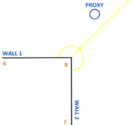
end point on the wall that is closest to the proxy and the angle between the proxy and the wall. Each end point of a wall touches the end point of another wall so walls always meet at corners (see point B in Figure 2). If the angle between the proxy and the wall is smaller than half of the total corner angle, set the closest corner point as the "force point"; else, this wall does not contribute a "force point." To explain this further: when two walls meet at a corner, only one wall can be responsible for
contributing the force point. Otherwise, the force calculated from this corner point will be doubled. Thus each wall has a certain angle range in which its corner point is valid (see Figure 2).
PROXY
0
WALL 1
A B
Figure 2. Illustration of how to determine which wall contributes the corner point (B). The figure shows that the angle from the proxy to WALL 1 (ABProxy) is less than half the
total angle subtended by the two walls (yellow line) so the endpoint of WALL I contributes the force.
4.3 EXPERIMENT #1: FORCE FIELDS IN ENCLOSED SPACES
The goal of this experiment was to determine if repulsive force fields could be used to help learn about indoor spaces. In this experiment, subjects attempted to learn a floor plan of three rooms interconnected by three hallways. Then subjects were asked to build a physical model representing the space to evaluate their understanding of the
4.3.1 METHODS
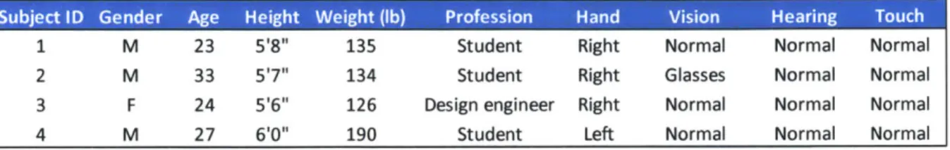
Subjects
Subjects ranged from 23 to 33 years of age. Three subjects were male, one subject was female. Three subjects were right-handed, one subject was left-handed. All had normal or corrected normal vision, hearing, and sense of touch. Table 1 provides a summary of the tested subjects.
S M 23 H 5 13 Ste t RiHt No norma
1 M 23 51811 135 Student Right Normal Normal Normal
2 M 33 51711 134 Student Right Glasses Normal Normal
3 F 24 5'6" 126 Design engineer Right Normal Normal Normal
4 M 27 6'0" 190 Student Left Normal Normal Normal
Table 1. Repulsive force field experiment #1 subjects
Arrangement
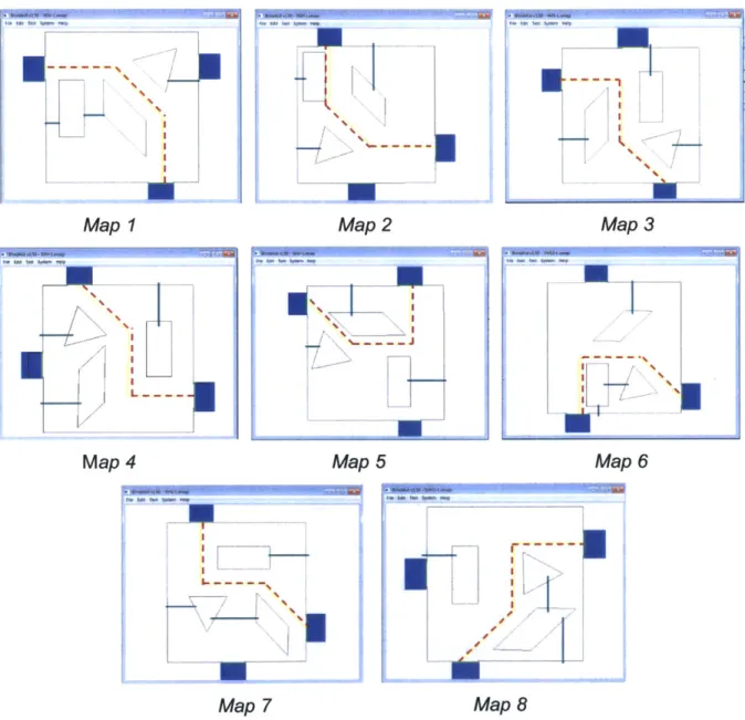
Four different layouts of similar complexities were used in the experiment (Figure
3). The x and y dimensions of the virtual workspace shown in the figure are 21.3 m by 16.0 m, where x is horizontal on the page and y is vertical on the page. In order to
maintain a comparable level of complexity, the VE layouts consisted of alternating the same set of basic components (e.g., rooms and hallways) and relations (e.g., hallway to room, hallway to hallway).
l Eon FM -m "Map
Map I
Fe Ev Teo -~e HOP
Map 3 Map 4
Figure 3. Repulsive force field experiment #1 map layouts
Each map had three square rooms of varying sizes (small, medium, large) with each size represented once. Note that the corresponding virtual dimensions of the rooms were 2.1 m, 3.8 m, 5.7 m, respectively. Rooms were connected by three
rectangular hallways of three potential widths (thin, medium, wide: 0.85 m, 1.7 m, 2.5 m) and three potential lengths (short, middle, long: 4.2 m, 6.1 m, 8.5 m), with each potential width and length represented once. For example, one map could contain a long thin hallway, a short wide hallway, and a middle medium hallway, but another map might consist of a middle thin hallway, a short medium hallway, and a long wide hallway. There was at least one horizontal hallway and one vertical hallway (hallway orientation).
Each hallway intersected at least one other hallway and one hallway always ended in a dead-end (hallway parameters). Each room connected to a hallway but no more than two rooms were connected to the same hallway; one room connected to the left side of a hallway, another room connected to the right side of a hallway and the third room connected to the end of a hallway (hallway-to-room parameters). Additionally, the total distance between rooms - the sum of the distances from Room 1 to Room 2, Room 2 to
Room 3, and Room 3 to Room 1 - was equal across all four layouts. Finally, the force
field distance was optimized such that the proxy was constrained to the center line of the thinnest hallway but allowed to be move side-to-side with ease in the widest
hallway. Subjects were not given the ability to adjust the force constant or radius of influence.
To simplify the map, all intersecting angles were 90 degrees and there were exactly eight potential connection points for a hallway. This meant that a room or
hallway could only connect to another hallway at one of eight points: top left, top middle, top right, bottom left, bottom middle, bottom right, left and right (Figure 4).
Sample Hallway
Figure 4. The orange segments represent the eight potential hallway connection points Procedure
The experimental task was to explore a floor plan of three rooms interconnected
by three hallways until the subject believed he/she had a good understanding of it, and
then identify different aspects of the layout using a physical modeling kit immediately after each trial. Aspects the user was asked to focus on included: room size, hallway widths and lengths, placement of rooms in relation to hallways, and hallway
intersections. The experimental task was performed as a training trial and a test trial under each condition (No Forcefield, Forcefield), for a total of four trials. Table 2 presents the nominal order of the trials which were counter balanced across subjects. Either the No Forcefield condition was presented first in the Training #1 and Test #1 trials, and then the Forcefield condition in the second set of trials, or vice versa. The four maps were randomly assigned to the four trials for each subject. See Appendix B.1 for the actual ordering for each subject.
Training #1 No Forcefield 1
Test #1 No Forcefield 2 Training #2 Forcefield 3 Test #2 Forcefield 4
Table 2. Nominal set of trials for repulsive force field experiment #1
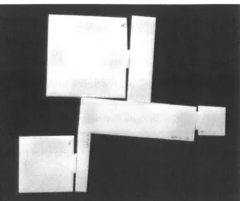
In addition to the general procedure described in Section 3, subjects were introduced to a physical modeling kit that consisted of magnetic laser-cut % inch thick acrylic replicas of the hallways and rooms to be used in the identification task (see Figure 5 for an example completed model).
Figure 5. Example of a completed model. This is a model of Map 2 completed by Subject 4. The width of the region shown is eight inches.
Once the subject had completed the entire experiment, he/she was asked the following questions:
a. Was the task difficult? What parts were difficult? What parts were easy?
b. Did one condition seem more difficult than the other? Why?
c. What information (e.g., room size, hallway size) was made easier or more difficult with force fields?
d. Was using the force field easy or difficult?
e. Did using the force field help? If yes, in what way?
f. Do you have any other comments?
Variables
The dependent variables in this experiment included preference for the feature (i.e. the force field), build error (the number of errors in the physical model), build time (the time needed to build the physical model of the map), and exploration time (the time needed to learn the map layout). Build errors included selecting the wrong length or width hallway, placing a room in the wrong general location (e.g., placing the small room where the large room should be), and connecting a hallway to another hallway or room at the incorrect intersection point (of eight potential points on a hallway). See Table 3.
Use of force field Preference for force field Number of hallways Hallway orientation
Build error Size of hallways Hallway parameters
Build time Number of rooms Total room-to-room distance
Exploration time Size of rooms Hallway-to-room parameters
Table 3. Repulsive force field experiment #1 variables
4.3.2 RESULTS / DISCUSSION
Figure 6 shows the mean exploration time, physical model build time, and build error averaged across subjects for the two conditions, with lower values corresponding to better performance (error bars in the figure are ± 1 standard deviation). The complete set of data is included in Appendix B.1. The mean times for exploring the map and building the physical model, and the mean number of errors in the model were approximately equal for both conditions. These results suggest that while repulsive force fields can be used, they do not add to the user's ability to navigate and understand the VE.
Mean Exploration Time Mean Build Time Mean Build Error
800 150 3.0 2.5 1 600
0
4
100 2.001
1.S~E
501. 2000Force Field No Force Field Force Field No Force Field Force Field No Force Field Figure 6. Performance metrics by condition of repulsive force field experiment #1
Indeed, the post experiment questionnaire revealed that users either did not notice the repulsive force field or actively ignored it. Observations of subject exploration during testing confirmed this. Additionally, all subjects expressed an affinity for
physically touching the walls as opposed to relying on the force fields emanating from the walls. Without vision, subjects looked for solid objects to ground them during
exploration; the force field, with its variable "surface," complicated the task of pinpointing and retaining the user's position in space.
Interestingly, the force field condition had a much larger standard deviation for build error as compared to the no force field condition, despite having approximately equal means. This may have been due to the issue that the force field was not intuitive. Perhaps with practice the build accuracy might improve.
While the application of repulsive force fields to all surfaces may not be ideal, it may be useful in a smaller scope to provide information about specific objects, such that it does not affect the user's ability to ground himself/herself. This leads us into the second repulsive force field experiment.
4.4 EXPERIMENT #2: FORCE FIELDS IN OPEN SPACES
The goal of this experiment was to determine if repulsive force fields could be used to learn about outdoor spaces. In this experiment, the virtual objects of interest represented buildings and the task involved learning their locations while traveling along a virtual street.
4.4.1 METHODS Subjects
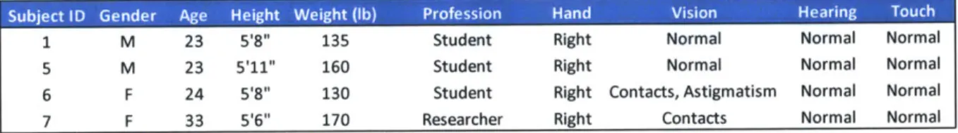
Subjects ranged from 23 to 33 years of age. There were two male subjects and two female subjects. All subjects were right-handed and had normal or corrected normal vision, hearing and sense of touch. Only subject 1 took part in the previous experiment.
See Table 4.
Subject ID Gender Age Height Weight (lb) Profession Hand Vision Hearing Touch 1 M 23 518" 135 Student Right Normal Normal Normal
5 M 23 5'11" 160 Student Right Normal Normal Normal
6 F 24 5'811 130 Student Right Contacts, Astigmatism Normal Normal
7 F 33 516" 170 Researcher Right Contacts Normal Normal Table 4. Repulsive force field experiment #2 subjects
Arrangement
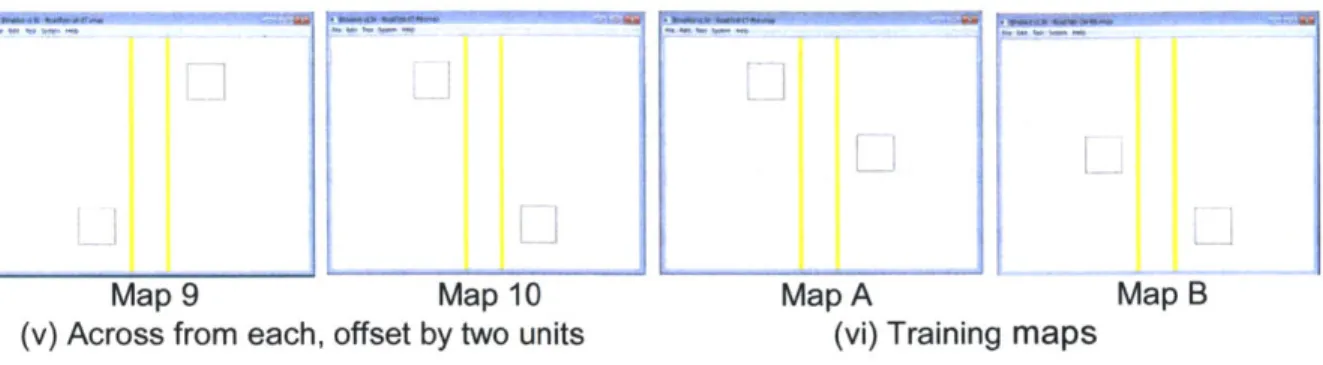
A total of 12 different layouts of similar complexities (Figure 7) were used for the
22 tasks; two maps were used for the training trials and the remaining ten maps were used for the test trials in both conditions (each test map was used in the force field condition and the no force field condition). Again, we designed the maps to be similar in complexity. The virtual workspace was 8.3 m in width and 6.5 m in length. Each map had a centered road 0.9 m wide, bounded by curbs on each side and two square buildings (1.0 m on a side) located somewhere outside of the road. Curbs were
the distance to the ceiling. Buildings were made of four walls that extended from floor to ceiling. The subject was able to move along the edge of the curb as a guide if the proxy was touching the ground, but could also jump over the curb and explore the rest of the
map if the proxy was moved up slightly in the vertical axis (out of the page). There were six potential locations for the two buildings - bottom left, middle left, top left, bottom right, middle right, or top right.
While the maps were believed to be similar in complexity as they were comprised of the same components, the subject could still believe one map was more challenging to explore than another based on the placement of the two buildings. Thus, we aimed to create a uniform distribution of different map arrangements. Specifically, the test maps consisted of five categories of building arrangements with two maps in each category as shown in Figure 7. The training maps were a sixth category. Lastly, the force fields emanating from the buildings were designed so that users could sense the buildings while moving along the road; the force field's radius of influence was approximately the
length of one side of a building in the horizontal plane.
Map1 Map2 Map3 Map4
(i) Directly across from each other (ii) Next to each other on the same side
Map5 Map 6 Map 7 Map8
(iii) Separated by one unit on the same side (iv) Across from each other, offset by one unit
Map9 Map 10 Map A
(v) Across from each, offset by two units (vi) Training maps
Figure 7. Repulsive force field experiment #2 map layouts
Map B
Procedure
The experimental task was to explore a virtual street with buildings on either sides of it and identify the locations of the buildings verbally. Overall, the procedure was very similar to that of Experiment #1. Specifically, in terms of counterbalancing the conditions, either the No Forcefield condition was presented first with its training trial followed by ten test trials, and then the Forcefield condition with its training and ten test trials, or vice versa. Table 5 presents the nominal order of the trials which were counter balanced across subjects. See Appendix B.2 for the actual ordering for each subject. The two training maps were randomly assigned to the two conditions and the ten test maps were randomly assigned to the ten tests of each condition. The main difference in
Experiment #2 was that subjects gave verbal responses to indicate the locations of the buildings rather than build a physical model. The maps were also simpler, enabling more trials in a test session. The post experiment questionnaire was identical.
Tra Codto Map0
Training #1 Force Field A
Test #1 Force Field 1
Test #2 Force Field 2 Test #3 Force Field 3
Test #4 Force Field 4 Test #5 Force Field 5
Test #6 Force Field 6
Test #7 Force Field 7
Test #8 Force Field 8
Test #9 Force Field 9
Test #10 Force Field 10
Table 5. Repulsive force field
Training #2 No Forcefield B Test #11 No Forcefield 1 Test #12 No Forcefield 2 Test #13 No Forcefield 3 Test #14 No Forcefield 4 Test #15 No Forcefield 5 Test #16 No Forcefield 6 Test #17 No Forcefield 7 Test #18 No Forcefield 8 Test #19 No Forcefield 9 Test #20 No Forcefield 10
Variables
The dependent variables in this experiment were: preference for the feature, identification error (the number of buildings the subject located incorrectly), and exploration time (the time needed to locate the buildings). See Table 6.
Ineedn Varabl Deenen Vaibe Cotole Vari0ables
Use of force field Preference for force field
Identification error Exploration time
Table 6. Repulsive force
Size of road Location of road
Size of curbs Location of curbs
field experiment #2 variables
Size of buildings Number of buildings
Location of buildings
4.4.2 RESULTS / DISCUSSION
Figure 8 shows the mean exploration time and identification error by condition averaged across subjects, with lower values corresponding to better performance (error
bars in the figure are ± 1 standard deviation). The exploration time of the two conditions was essentially equal; and on occasion, the force field condition took longer (see
Appendix B.2). In the eighty test trials conducted, only two trials, both in the force field condition, resulted in an identification error. This may imply that mistakes are more easily made in the force field condition. Similar to the prior experiment, the results
suggest that the repulsive force field is usable but does not increase learning efficiency. Mean Exploration Time Mean Identification Error
70 0.30 60 0.25 500 S40 0.20 E 30 J-01 20 E 0:20 10 20.05 I 0 0.00
Force Field No Force Field Force Field No Force Field
Figure 8. Performance metrics by condition of repulsive force field experiment #2 Discussions with the subjects revealed that they found the force field feature easy-to-use because it required less overall exploration; however, they also expressed a few issues. Comments concerning issues included:
* The force field was helpful until you tried to touch the building, at which point it pushed you away.
* It took longer to translate and verify the locations of the buildings because you could only sense that it was there. However, practicing made the ability to locate easier.
e You had to know exactly where you were in the map for it to be helpful; otherwise
there was no clear location reference.
The results of both experiments were insufficient to support the use of repulsive force fields to improve global sensing. While more experimentation to support or refute this claim was possible, we believed that the preliminary tests were convincing enough to switch gears and consider another type of force field.
4.5 DISCUSSION OF LEARNING CURVES IN THE TWO EXPERIMENTS
Before moving on to development and testing of the new force field, we did the following analysis and identified a useful change to the initial experimental procedure.
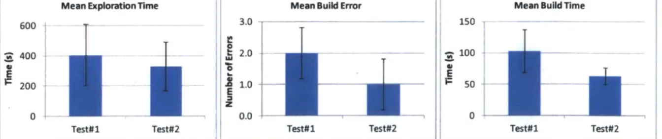
Specifically, in the first two force field experiments, the training and test trials were grouped together for each condition. This meant that the subject was trained and tested
in the first condition, and then trained and tested in the second condition. In our initial design of the experiment, having one training was thought to be sufficient as the subject was given as much time as he/she needed to feel comfortable with the apparatus. Analysis of the performance metrics with respect to the first and second tests of
Experiment #1, independent of the force field condition, shows a modest improvement across all three metrics (Figure 9).
Mean Exploration Time Mean Build Error Mean Build lime
600 3.0 150 Itz 400 20 . 1004 EE 00 0 0 0.0 0
Test#1 Test#2 Test#1 Test#2 Test#1 Test#2
Figure 9. Performance metrics by test number of force field experiment #1 independent of condition
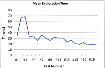
A similar trend can be observed for the second experiment (Figure 10). The first
Based on these observations, we adjusted the procedures of all following experiments. The procedure conducts trainings before any tests to provide sufficient time to stabilize the learning curve.
Mean Exploration Time
80 70 _ 60 50 40 ---1 30 20 10 0 #1 #3 #5 #7 #9 #11 #13 #15 #17 #19 Test Number
5
ATTRACTIVE FORCE FIELDS FOR GLOBAL HAPTIC
SENSING APPLIED TO ROUTE GUIDANCE
Route guidance is an important aspect of navigation for all people. Route
guidance can provide users with the most efficient route to a specific destination as well as alternate routes. Depending on the size of the map, finding places like the nearest grocery store without guidance can be very difficult and even impossible. While there are many ways to implement a guide agent, the most commonly used guide strategies are to provide instructions visually and/or verbally. With blind people, the audio
channels can become overloaded because much more information is presented aurally. This issue is also apparent in the BlindAid program; audio is an easy tool to use to convey information so using haptics when possible can alleviate the burden placed on the audio channels.
Because simply being lead through a route is insufficient for route learning, we thought to use attractive force fields for global sensing so that users could keep track of objects (or the route), while still learning the space around them. We first devised a concept to set tether points while exploring so that users could explore without losing track of where they were. From this, stemmed the idea of creating a path of tether points that would comprise a route to guide the user (by pulling him/her along it) while still allowing the user to explore around the route. We decided to investigate global sensing with an attractive force field in the context of this application.
The remainder of the chapter presents our development of the haptic route guide chronologically, beginning with discussions of the initial design and implementation of the guide. We then discuss the first developmental experiment in which we evaluated four potential haptic guide designs and selected the most promising one. The plan was to compare the most promising haptic guide to conventional alternatives in a main experiment. Before moving on to the main experiment, we developed an audio guide to provide a standard for comparison in the main experiment along with the no guide condition. The audio guide development involved an initial design and implementation phase in which four candidate audio guides were created, and then experimentally evaluated to select the best one similar to the initial haptic guide development. The
experimental procedures were also refined in the first two experiments for the main experiment. The results of initial tests in the main experiment suggested further improvements to the haptic guide were needed. The haptic guide design was revised accordingly and the final main experiment was performed. The final results showed the haptic guide was indeed effective for global sensing and route guidance.
5.1 INITIAL DESIGN
GPS devices are commonly used by drivers for route guidance in the real world.
These devices use audio to verbally convey instructions about the route at key points, called way points, where the user must act to stay on the route. Typically, a GPS will first inform the user that a new route action will be required ahead and then instruct the action. GPS devices for blind persons typically follow this methodology, but can also convey additional audio information that is normally presented visually for sighted users. Such additional information includes the user's current location with respect to
addresses, streets and intersections. Because these types of audio features can always be added to the haptic guide later, we focused primarily on developing the haptic guide.
5.1.1 HAPTIc GUIDE COMPONENTS
There are three components of the initial haptic guide concept that we proposed:
(1) guide line, (2) tether, (3) forward force. Guide Line
The guide line (initial concept) is a set of line segments going from one way point to the next along a route. While other shapes could be used to specify the route (e.g., a
surface representing a sidewalk or street), a set of line segments was thought to be sufficient and certainly the simplest way to start. Initially, the concept represented line segments haptically as snap-to objects. A snap-to object produces a strong attractive force to the proxy when the two are very close to each another. We had also considered
representing way points and curved segments haptically. However, since curve segments could be represented by straight line segments and were not needed in the actual experiments, we decided to work with line segments.
Tether
The "tether," which allows the user to explore the region around the route while keeping track of the guide line, is an attractive force between the proxy and another point on the guide line - this point is called the tether point or anchor point. Anchor points may be located at any point along the guide line, nominally shifting in the forward direction as the user progresses along the route. The placement of anchor points can be determined using a number of different strategies. These strategies include setting the anchor point to: the last touched point on the guide line, the closest point to the proxy on the guide line (moves with the user), and important way points such as turns that can be selected manually or automatically to progress in the forward or reverse direction. Additionally, the attractive force can be constant or vary by distance, linearly or non-linearly.
Forward Force
The "forward force" concept is a force that can push/pull the user in the forward direction along the route, toward the destination. A few strategies were devised for how to use the forward force: (1) the anchor point could move along the guide line, pulling the user along via the tether (2) the forward force acts only when the user is snapped to the guide line, (3) the tether to way points acts as a forward force (by placing the tether point ahead of the user). Again, the force can be constant, linear, or non-linear.
5.1.2 SELECTION OF CANDIDATE HAPTIc GUIDES
We explored many alternative design concepts of the proposed haptic guide, involving different implementation and combinations of the three components.
e Guide line only gives more information than no assistance but does not provide
information about the forward direction.
e Tether to last touched point on guide line produces no forces when the user is in
contact with the guide line, but creates an attractive force to the last touched point on the guide line when the user moves away from it.
* Tether to closest point on guide line produces an attractive force to the closest point on the guide line only when the user is not in contact with it. The closest